EP0942414A1 - Abspielgerät für optische Platte - Google Patents
Abspielgerät für optische Platte Download PDFInfo
- Publication number
- EP0942414A1 EP0942414A1 EP99103904A EP99103904A EP0942414A1 EP 0942414 A1 EP0942414 A1 EP 0942414A1 EP 99103904 A EP99103904 A EP 99103904A EP 99103904 A EP99103904 A EP 99103904A EP 0942414 A1 EP0942414 A1 EP 0942414A1
- Authority
- EP
- European Patent Office
- Prior art keywords
- optical disk
- astigmatic
- objective lens
- focal
- photodetector
- Prior art date
- Legal status (The legal status is an assumption and is not a legal conclusion. Google has not performed a legal analysis and makes no representation as to the accuracy of the status listed.)
- Granted
Links
- 230000003287 optical effect Effects 0.000 title claims abstract description 78
- 238000001514 detection method Methods 0.000 claims abstract description 11
- 239000011159 matrix material Substances 0.000 claims description 2
- 201000009310 astigmatism Diseases 0.000 description 14
- 238000000034 method Methods 0.000 description 10
- 230000003247 decreasing effect Effects 0.000 description 5
- 230000007423 decrease Effects 0.000 description 2
- 238000005259 measurement Methods 0.000 description 2
- 230000004807 localization Effects 0.000 description 1
- 230000005389 magnetism Effects 0.000 description 1
- 238000004519 manufacturing process Methods 0.000 description 1
Images


Classifications
-
- G—PHYSICS
- G11—INFORMATION STORAGE
- G11B—INFORMATION STORAGE BASED ON RELATIVE MOVEMENT BETWEEN RECORD CARRIER AND TRANSDUCER
- G11B7/00—Recording or reproducing by optical means, e.g. recording using a thermal beam of optical radiation by modifying optical properties or the physical structure, reproducing using an optical beam at lower power by sensing optical properties; Record carriers therefor
- G11B7/12—Heads, e.g. forming of the optical beam spot or modulation of the optical beam
- G11B7/135—Means for guiding the beam from the source to the record carrier or from the record carrier to the detector
- G11B7/1353—Diffractive elements, e.g. holograms or gratings
-
- G—PHYSICS
- G11—INFORMATION STORAGE
- G11B—INFORMATION STORAGE BASED ON RELATIVE MOVEMENT BETWEEN RECORD CARRIER AND TRANSDUCER
- G11B7/00—Recording or reproducing by optical means, e.g. recording using a thermal beam of optical radiation by modifying optical properties or the physical structure, reproducing using an optical beam at lower power by sensing optical properties; Record carriers therefor
- G11B7/007—Arrangement of the information on the record carrier, e.g. form of tracks, actual track shape, e.g. wobbled, or cross-section, e.g. v-shaped; Sequential information structures, e.g. sectoring or header formats within a track
- G11B7/00718—Groove and land recording, i.e. user data recorded both in the grooves and on the lands
-
- G—PHYSICS
- G11—INFORMATION STORAGE
- G11B—INFORMATION STORAGE BASED ON RELATIVE MOVEMENT BETWEEN RECORD CARRIER AND TRANSDUCER
- G11B7/00—Recording or reproducing by optical means, e.g. recording using a thermal beam of optical radiation by modifying optical properties or the physical structure, reproducing using an optical beam at lower power by sensing optical properties; Record carriers therefor
- G11B7/08—Disposition or mounting of heads or light sources relatively to record carriers
- G11B7/09—Disposition or mounting of heads or light sources relatively to record carriers with provision for moving the light beam or focus plane for the purpose of maintaining alignment of the light beam relative to the record carrier during transducing operation, e.g. to compensate for surface irregularities of the latter or for track following
- G11B7/0908—Disposition or mounting of heads or light sources relatively to record carriers with provision for moving the light beam or focus plane for the purpose of maintaining alignment of the light beam relative to the record carrier during transducing operation, e.g. to compensate for surface irregularities of the latter or for track following for focusing only
- G11B7/0909—Disposition or mounting of heads or light sources relatively to record carriers with provision for moving the light beam or focus plane for the purpose of maintaining alignment of the light beam relative to the record carrier during transducing operation, e.g. to compensate for surface irregularities of the latter or for track following for focusing only by astigmatic methods
-
- G—PHYSICS
- G11—INFORMATION STORAGE
- G11B—INFORMATION STORAGE BASED ON RELATIVE MOVEMENT BETWEEN RECORD CARRIER AND TRANSDUCER
- G11B7/00—Recording or reproducing by optical means, e.g. recording using a thermal beam of optical radiation by modifying optical properties or the physical structure, reproducing using an optical beam at lower power by sensing optical properties; Record carriers therefor
- G11B7/12—Heads, e.g. forming of the optical beam spot or modulation of the optical beam
- G11B7/135—Means for guiding the beam from the source to the record carrier or from the record carrier to the detector
- G11B7/1372—Lenses
Definitions
- the present invention relates to an optical disk apparatus for recording/reproducing information by using a light beam and, more particularly, to an optical disk apparatus for recording information on grooves and/or lands formed in an optical recording medium.
- An optical disk apparatus records information on and reproduces recorded information from grooves and/or lands formed in an optical recording medium by utilizing optical magnetism or phase change.
- a laser beam must irradiate the grooves and lands after it is focused by using an objective lens.
- a focal position shift of the laser beam is detected, and focusing of the objective lens is controlled on the basis of the detected focal position shift.
- a method called astigmatic method is widely used as a method of detecting this focal position shift.
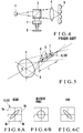
- an exit beam from a laser source 1 is focused by an objective lens 4 to form a fine spot through a beam splitter 3, to irradiate the recording surface of an optical disk 5.
- the beam reflected by the optical disk 5 is split by the beam splitter 3 and converted by an astigmatic element 7, e.g., a cylindrical lens, that generates astigmatism into an astigmatic beam in which its focal positions differ between the X and Y directions on a plane perpendicular to the traveling direction of the beam, as shown in Fig. 5.
- the astigmatic beam emerging from the astigmatic element 7 is received by a 4-division photodetector 8 constituted by 4 photodetection elements to detect its focal shift amount.
- the beam shape on the 4-division photodetector 8 changes in accordance with the focal shift amount (positions A to C) as shown in Figs. 6A to 6C.
- the difference in focal shift amount between the grooves and lands is considerably larger than the depth (about 80 nm with a wavelength of 650 nm) 1/8 a wavelength ⁇ of the laser source, which is the depth of the grooves employed in a general optical disk, and sometimes reaches a value of about 0.3 ⁇ m.
- the depth of the grooves in this conventional case is the one with which the track error signal in the push-pull method becomes the maximum when tracking adjustment is performed by utilizing a diffracted beam, as described above.
- an optical disk apparatus comprising an optical disk on which recording tracks are formed in both grooves and lands thereof, a laser source for emitting a laser beam, an objective lens for focusing the laser beam emitted by the laser-source to form a fine spot on a recording track of the optical disk, an astigmatic element placed in a convergent optical system for focusing the beam reflected by the optical disk, to receive the beam reflected by the optical disk and emit an astigmatic beam, and a photodetector for detecting the astigmatic beam emerging from the astigmatic element, the optical disk apparatus serving to perform at least focal adjustment of the objective lens by using a detection signal from the photodetector, wherein a relation 0.8 ⁇ ⁇ /(Tp ⁇ NA) ⁇ 1.1 is satisfied where ⁇ is a wavelength of the laser beam emitted by the laser source, NA is a numerical aperture of the objective lens, and Tp is a pitch size of the grooves.
- Fig. 1 schematically shows the arrangement of an optical disk apparatus according to an embodiment of the present invention.
- a laser beam emitted by a laser source 101 and having a wavelength ⁇ is converted by a collimator lens 102 into a parallel beam.
- the parallel beam emerging from the collimator lens 102 passes through a beam splitter 103 and is focused by an objective lens 104 having a focal length f and a numerical aperture N4 to form a fine spot on the recording surface of an optical disk 105.
- Grooves 109 and lands 110 are alternately, spirally formed on the optical disk 105 and are respectively recorded with information.
- the period, i.e., the pitch size, of the grooves 109 is Tp.
- the beam reflected by the optical disk 105 is converted by the objective lens 104 into a parallel beam and is reflected and deflected by the objective lens 104.
- the deflected beam emerging from the objective lens 104 is focused by a focusing lens 106 having a focal length F and passes through an astigmatic element 107 such as a cylindrical lens to form an astigmatic beam having different focal positions in the X and Y directions on a plane perpendicular to the optical axis.
- This astigmatic beam is received by a 4-division photodetector 108 constituted by four photodetection elements divided into a 2 x 2 matrix.
- the 4-division photodetector 108 is placed at an intermediate position between the two focal positions of the astigmatic beam in the direction of optical axis.
- the dividion lines of the photodetection elements that intersect each other in a criss-cross manner form an angle of 45° in the X and Y directions of the astigmatic element 107.
- the shape of the astigmatic beam on the 4-division photodetector 108 changes in accordance with the in-focus state of the objective lens 104 with respect to the optical disk 105, as shown in Figs. 6A to 6C. Accordingly, a focal shift amount having an S-shaped curve indicated by the solid line in Fig. 7 can be obtained by summing detection signals detected by divisional regions (photodetection elements) 8a and 8d, and 8b and 8c at the diagonal positions of the 4-division photodetector 108 and calculating differences between the respective sum signals. The position of the optical axis of the objective lens 104 with respect to the optical disk 105 is adjusted such that this focal shift amount becomes zero, thus enabling focal adjustment with respect to the optical disk 105.
- a position shift signal in the direction of track width i.e., a tracking signal
- a tracking signal can be detected simultaneously, so that tracking adjustment can be performed simultaneously.
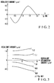
- the present inventor examined the relationship among the focal shift amount between the grooves 109 and lands 110, as shown in Figs. 8A and 8B, and the respective preset values of the optical disk apparatus, and found out that the pinch size Tp of the grooves 109, the numerical aperture NA of the objective lens 104, and a value obtained from the wavelength ⁇ of the laser beam emitted by the laser source 101, i.e., ⁇ /(Tp ⁇ NA) , had a correlation with the focal shift amount.
- Fig. 2 shows a graph showing a curve of this correlation, in which the axis of abscissa represents ⁇ /(Tp ⁇ NA) and the axis of ordinate represents the focal shift amount ( ⁇ m).
- This characteristic curve differs depending on the depth of the grooves 109.
- a case wherein the depth of the grooves 109 is 1/8 ⁇ with which the track error signal obtained by the push-pull method becomes the maximum is shown.
- ⁇ /(Tp ⁇ NA) is a parameter indicating to which position of the opening of the objective lens 104 the center of the 1st-order diffracted beam diffracted by the grooves 109 having the uniform pitch size on the optical disk 105 returns.
- the parameter is set such that the focal shift amount becomes zero. For example, if this parameter is set to "2", the focal position shift amount can be decreased to zero. More specifically, when the parameter is "2", the 1-st order diffracted beam is located outside the objective lens 104. A beam distribution identical to that obtained when the beam is reflected by a flat surface having no grooves 109 can be obtained, and the focal shift amount becomes zero.
- the pitch size Tp of the grooves 109 is to be increased.
- Tp is to increase the gap among the grooves 109. Therefore, the number of grooves 109 in the optical disk 105 is decreased to decrease the recording density of the optical disk 105. Hence, this method cannot be employed in high-density recording.
- the parameter is set to a value slightly smaller than "1" with which the focal shift amount causes zero crossing.
- An accurate value that causes this zero crossing slightly changes depending on other elements such as the focal length.
- the wavelength ⁇ of the laser beam emitted by the laser source 101, the numerical aperture NA of the objective lens 104, and the pitch size Tp of the grooves 109 are designed to satisfy: 0.8 ⁇ ⁇ (Tp ⁇ NA) ⁇ 1.1 then the focal shift amount between the grooves 109 and lands 110 can be set to zero or a value close to zero, as indicated by the solid line in Fig. 7.
- the present inventor also studied the equivalent astigmatism amount (f2/F2) ⁇ L , obtained by replacing the length L (Fig. 5) in the direction of optical axis between the two focal positions generated by the focusing lens 106 and astigmatic element 107, i.e., the astigmatism amount L, with an astigmatism amount of the optical disk 105 obtained by the objective lens 104, by using a value ⁇ /(Tp ⁇ NA) as the parameter.
- Fig. 3 shows that when the equivalent astigmatism amount increases, even if the parameter is kept unchanged, the focal shift amount increases.
- the present invention can similarly be applied to an optical system in which a finite-system objective lens also serves as a collimator lens and a detection-system focusing lens, in the same manner as in the arrangement shown in Fig. 4, and the focal length of the optical disk side is f and the focal length of the detection system side is F.
- a hologram element can be utilized as an astigmatic element for generating astigmatism.
- the focal shift amount can be set to zero or a value close to zero.
- the focal point signal shift amount can be set to zero or a value close to zero regardless of a difference in equivalent astigmatism amount.
Landscapes
- Physics & Mathematics (AREA)
- Optics & Photonics (AREA)
- Optical Head (AREA)
- Optical Recording Or Reproduction (AREA)
Applications Claiming Priority (2)
| Application Number | Priority Date | Filing Date | Title |
|---|---|---|---|
| JP10061735A JP3123500B2 (ja) | 1998-03-12 | 1998-03-12 | 光ディスク装置 |
| JP6173598 | 1998-03-12 |
Publications (2)
| Publication Number | Publication Date |
|---|---|
| EP0942414A1 true EP0942414A1 (de) | 1999-09-15 |
| EP0942414B1 EP0942414B1 (de) | 2008-06-25 |
Family
ID=13179763
Family Applications (1)
| Application Number | Title | Priority Date | Filing Date |
|---|---|---|---|
| EP99103904A Expired - Lifetime EP0942414B1 (de) | 1998-03-12 | 1999-03-04 | Abspielgerät für optische Platte |
Country Status (4)
| Country | Link |
|---|---|
| US (1) | US6266302B1 (de) |
| EP (1) | EP0942414B1 (de) |
| JP (1) | JP3123500B2 (de) |
| DE (1) | DE69938945D1 (de) |
Families Citing this family (5)
| Publication number | Priority date | Publication date | Assignee | Title |
|---|---|---|---|---|
| JP4095766B2 (ja) * | 2000-10-20 | 2008-06-04 | 株式会社リコー | 光学ユニットの組立調整装置 |
| TWI248244B (en) | 2003-02-19 | 2006-01-21 | J P Sercel Associates Inc | System and method for cutting using a variable astigmatic focal beam spot |
| CN100530379C (zh) * | 2006-07-19 | 2009-08-19 | 清华大学深圳研究生院 | 激光读取头信号拾取光路结构 |
| US20130256286A1 (en) * | 2009-12-07 | 2013-10-03 | Ipg Microsystems Llc | Laser processing using an astigmatic elongated beam spot and using ultrashort pulses and/or longer wavelengths |
| JP6299600B2 (ja) | 2012-10-15 | 2018-03-28 | ソニー株式会社 | 微小粒子測定装置 |
Citations (5)
| Publication number | Priority date | Publication date | Assignee | Title |
|---|---|---|---|---|
| EP0553541A1 (de) * | 1992-01-20 | 1993-08-04 | Pioneer Electronic Corporation | Optische Platte, und Wiedergabegerät für optische Platte |
| EP0664541A1 (de) * | 1994-01-19 | 1995-07-26 | Kabushiki Kaisha Toshiba | Optische Platte und Gerät für optische Platte |
| DE19640838A1 (de) * | 1995-10-04 | 1997-04-10 | Samsung Electronics Co Ltd | Optische Aufzeichnungs- und Wiedergabevorrichtung |
| EP0810598A2 (de) * | 1996-05-30 | 1997-12-03 | Hitachi, Ltd. | Gerät für optische Platten |
| WO1998049680A1 (en) * | 1997-04-25 | 1998-11-05 | Sanyo Electric Co., Ltd. | Recording medium and optical pickup device |
Family Cites Families (10)
| Publication number | Priority date | Publication date | Assignee | Title |
|---|---|---|---|---|
| JPS58185047A (ja) | 1982-04-23 | 1983-10-28 | Toshiba Corp | 光学的情報読取装置 |
| US5910932A (en) * | 1991-09-11 | 1999-06-08 | Sony Corporation | Optical disk and optical disk system with numerical aperture of objective lens related to protective layer thickness of optical disk |
| JPH05258320A (ja) | 1992-03-16 | 1993-10-08 | Hitachi Ltd | 焦点ずれ検出方法およびそれを用いた光情報処理装置 |
| JP2860229B2 (ja) * | 1993-06-25 | 1999-02-24 | 株式会社ケンウッド | 光ディスク記録再生装置 |
| JP2704107B2 (ja) | 1994-01-19 | 1998-01-26 | 株式会社東芝 | 光ディスクおよび光ディスク装置 |
| JPH09115185A (ja) | 1995-10-18 | 1997-05-02 | Dainippon Ink & Chem Inc | 光記録媒体および光情報検出装置 |
| JP3645020B2 (ja) * | 1995-12-12 | 2005-05-11 | 富士通株式会社 | 光情報検出装置 |
| JPH09231588A (ja) | 1996-02-26 | 1997-09-05 | Ricoh Co Ltd | 光ディスクドライブ |
| JP3658092B2 (ja) | 1996-07-19 | 2005-06-08 | 松下電器産業株式会社 | 光ピックアップヘッド装置、光情報処理装置及び光ピックアップヘッド装置の組立調整方法 |
| JPH1064104A (ja) | 1996-08-21 | 1998-03-06 | Pioneer Electron Corp | 非点収差フォーカスエラー信号生成方法及び光ピックアップ装置 |
-
1998
- 1998-03-12 JP JP10061735A patent/JP3123500B2/ja not_active Expired - Lifetime
-
1999
- 1999-03-04 DE DE69938945T patent/DE69938945D1/de not_active Expired - Lifetime
- 1999-03-04 EP EP99103904A patent/EP0942414B1/de not_active Expired - Lifetime
- 1999-03-12 US US09/266,884 patent/US6266302B1/en not_active Expired - Lifetime
Patent Citations (5)
| Publication number | Priority date | Publication date | Assignee | Title |
|---|---|---|---|---|
| EP0553541A1 (de) * | 1992-01-20 | 1993-08-04 | Pioneer Electronic Corporation | Optische Platte, und Wiedergabegerät für optische Platte |
| EP0664541A1 (de) * | 1994-01-19 | 1995-07-26 | Kabushiki Kaisha Toshiba | Optische Platte und Gerät für optische Platte |
| DE19640838A1 (de) * | 1995-10-04 | 1997-04-10 | Samsung Electronics Co Ltd | Optische Aufzeichnungs- und Wiedergabevorrichtung |
| EP0810598A2 (de) * | 1996-05-30 | 1997-12-03 | Hitachi, Ltd. | Gerät für optische Platten |
| WO1998049680A1 (en) * | 1997-04-25 | 1998-11-05 | Sanyo Electric Co., Ltd. | Recording medium and optical pickup device |
Also Published As
| Publication number | Publication date |
|---|---|
| JPH11259874A (ja) | 1999-09-24 |
| EP0942414B1 (de) | 2008-06-25 |
| US6266302B1 (en) | 2001-07-24 |
| DE69938945D1 (de) | 2008-08-07 |
| JP3123500B2 (ja) | 2001-01-09 |
Similar Documents
| Publication | Publication Date | Title |
|---|---|---|
| KR100231388B1 (ko) | 광헤드의 트래킹오차 검출장치(Optical Head Tracking Error Detection Device) | |
| US5391865A (en) | Optical pickup apparatus and optical grating assembly therefor | |
| KR100714381B1 (ko) | 광 레코딩 매체를 판독 또는 기록하기 위한 장치 및 그러한 장치에서 사용되는 회절 격자를 제작하는 방법 | |
| US5579298A (en) | Optical scanner having symmetry about an oblique divider | |
| US5754503A (en) | Optical device with improved focused error detection and tracing error detection for optical disk drive | |
| EP0583036B1 (de) | Einrichtung zur optischen Abtastung einer Oberfläche | |
| US5231621A (en) | Focus detector which serves to split off a portion of a detected light beam only when the detected light beam is not refocused at an expected refocus point | |
| US6266302B1 (en) | Optical disk apparatus | |
| US5673241A (en) | Focus detection mechanism and optical head and optical storage device that use it | |
| US6167017A (en) | Optical head assembly having means for detecting tracking errors based on astigmatisms generated by returning beams | |
| US5062094A (en) | Optical head for optical disk system | |
| KR970008230B1 (ko) | 광픽업장치 | |
| US5703863A (en) | Optical device which detects reflected light with a push-pull method without dividing the reflected light | |
| US6567353B1 (en) | Optical head with light receiving element surfaces divided into at least three light receiving areas | |
| EP0323320B1 (de) | Optischer Kopf und Spurführungsmethode unter Benutzung desselben | |
| PL131561B1 (en) | Apparatus for point-by-point scanning an information carrying surface | |
| US7573801B2 (en) | Optical pickup | |
| JPH08212566A (ja) | 合焦検出手段、光ヘッド、および光記憶装置 | |
| JP3303250B2 (ja) | 変位測定装置および光ピックアップ | |
| JP3415938B2 (ja) | 変位測定装置および光ピックアップ | |
| KR100191884B1 (ko) | 초점검출기구 및 그것을 사용한 광헤드와 광기억장치 | |
| JP3115761B2 (ja) | 光学ヘッド | |
| US5691970A (en) | Optical pickup for high-density recording/reproducing | |
| US6781104B1 (en) | Device for scanning an optical record carrier | |
| JP3544785B2 (ja) | 光学式記録再生装置 |
Legal Events
| Date | Code | Title | Description |
|---|---|---|---|
| PUAI | Public reference made under article 153(3) epc to a published international application that has entered the european phase |
Free format text: ORIGINAL CODE: 0009012 |
|
| 17P | Request for examination filed |
Effective date: 19990608 |
|
| AK | Designated contracting states |
Kind code of ref document: A1 Designated state(s): DE FR NL |
|
| AX | Request for extension of the european patent |
Free format text: AL;LT;LV;MK;RO;SI |
|
| AKX | Designation fees paid |
Free format text: DE FR NL |
|
| 17Q | First examination report despatched |
Effective date: 20061229 |
|
| GRAP | Despatch of communication of intention to grant a patent |
Free format text: ORIGINAL CODE: EPIDOSNIGR1 |
|
| GRAS | Grant fee paid |
Free format text: ORIGINAL CODE: EPIDOSNIGR3 |
|
| GRAA | (expected) grant |
Free format text: ORIGINAL CODE: 0009210 |
|
| AK | Designated contracting states |
Kind code of ref document: B1 Designated state(s): DE FR NL |
|
| REF | Corresponds to: |
Ref document number: 69938945 Country of ref document: DE Date of ref document: 20080807 Kind code of ref document: P |
|
| PLBE | No opposition filed within time limit |
Free format text: ORIGINAL CODE: 0009261 |
|
| STAA | Information on the status of an ep patent application or granted ep patent |
Free format text: STATUS: NO OPPOSITION FILED WITHIN TIME LIMIT |
|
| 26N | No opposition filed |
Effective date: 20090326 |
|
| REG | Reference to a national code |
Ref country code: NL Ref legal event code: SD Effective date: 20110216 |
|
| REG | Reference to a national code |
Ref country code: FR Ref legal event code: TP |
|
| REG | Reference to a national code |
Ref country code: DE Ref legal event code: R082 Ref document number: 69938945 Country of ref document: DE Representative=s name: MEISSNER, BOLTE & PARTNER GBR, DE Ref country code: DE Ref legal event code: R082 Ref document number: 69938945 Country of ref document: DE |
|
| REG | Reference to a national code |
Ref country code: DE Ref legal event code: R081 Ref document number: 69938945 Country of ref document: DE Owner name: KONINKLIJKE PHILIPS N.V., NL Free format text: FORMER OWNER: NEC CORP., TOKYO, JP Effective date: 20111205 |
|
| REG | Reference to a national code |
Ref country code: DE Ref legal event code: R082 Ref document number: 69938945 Country of ref document: DE Representative=s name: MEISSNER BOLTE PATENTANWAELTE RECHTSANWAELTE P, DE Effective date: 20111205 Ref country code: DE Ref legal event code: R082 Ref document number: 69938945 Country of ref document: DE Representative=s name: MEISSNER, BOLTE & PARTNER GBR, DE Effective date: 20111205 Ref country code: DE Ref legal event code: R081 Ref document number: 69938945 Country of ref document: DE Owner name: KONINKLIJKE PHILIPS N.V., NL Free format text: FORMER OWNER: KONINKLIJKE PHILIPS ELECTRONICS N.V., EINDHOVEN, NL Effective date: 20140328 |
|
| REG | Reference to a national code |
Ref country code: FR Ref legal event code: CD Owner name: KONINKLIJKE PHILIPS ELECTRONICS N.V., NL Effective date: 20141126 Ref country code: FR Ref legal event code: CA Effective date: 20141126 |
|
| REG | Reference to a national code |
Ref country code: FR Ref legal event code: PLFP Year of fee payment: 18 |
|
| REG | Reference to a national code |
Ref country code: FR Ref legal event code: PLFP Year of fee payment: 19 |
|
| PGFP | Annual fee paid to national office [announced via postgrant information from national office to epo] |
Ref country code: FR Payment date: 20170327 Year of fee payment: 19 Ref country code: NL Payment date: 20170327 Year of fee payment: 19 |
|
| PGFP | Annual fee paid to national office [announced via postgrant information from national office to epo] |
Ref country code: DE Payment date: 20170531 Year of fee payment: 19 |
|
| REG | Reference to a national code |
Ref country code: DE Ref legal event code: R119 Ref document number: 69938945 Country of ref document: DE |
|
| REG | Reference to a national code |
Ref country code: NL Ref legal event code: MM Effective date: 20180401 |
|
| PG25 | Lapsed in a contracting state [announced via postgrant information from national office to epo] |
Ref country code: NL Free format text: LAPSE BECAUSE OF NON-PAYMENT OF DUE FEES Effective date: 20180401 |
|
| PG25 | Lapsed in a contracting state [announced via postgrant information from national office to epo] |
Ref country code: DE Free format text: LAPSE BECAUSE OF NON-PAYMENT OF DUE FEES Effective date: 20181002 |
|
| PG25 | Lapsed in a contracting state [announced via postgrant information from national office to epo] |
Ref country code: FR Free format text: LAPSE BECAUSE OF NON-PAYMENT OF DUE FEES Effective date: 20180331 |