EP0943227A1 - Epandeur - Google Patents
Epandeur Download PDFInfo
- Publication number
- EP0943227A1 EP0943227A1 EP99200564A EP99200564A EP0943227A1 EP 0943227 A1 EP0943227 A1 EP 0943227A1 EP 99200564 A EP99200564 A EP 99200564A EP 99200564 A EP99200564 A EP 99200564A EP 0943227 A1 EP0943227 A1 EP 0943227A1
- Authority
- EP
- European Patent Office
- Prior art keywords
- implement
- axis
- drive
- gearwheel
- spreading
- Prior art date
- Legal status (The legal status is an assumption and is not a legal conclusion. Google has not performed a legal analysis and makes no representation as to the accuracy of the status listed.)
- Withdrawn
Links
- 230000007480 spreading Effects 0.000 title claims abstract description 58
- 239000000463 material Substances 0.000 title claims abstract description 9
- 230000008878 coupling Effects 0.000 claims abstract description 23
- 238000010168 coupling process Methods 0.000 claims abstract description 23
- 238000005859 coupling reaction Methods 0.000 claims abstract description 23
- 239000003337 fertilizer Substances 0.000 claims abstract description 12
- 210000000078 claw Anatomy 0.000 claims description 9
- 230000008719 thickening Effects 0.000 description 6
- 238000010276 construction Methods 0.000 description 2
- 230000009471 action Effects 0.000 description 1
- 230000003213 activating effect Effects 0.000 description 1
- 230000008901 benefit Effects 0.000 description 1
- 230000000903 blocking effect Effects 0.000 description 1
- 230000002349 favourable effect Effects 0.000 description 1
- 238000005461 lubrication Methods 0.000 description 1
Images


Classifications
-
- A—HUMAN NECESSITIES
- A01—AGRICULTURE; FORESTRY; ANIMAL HUSBANDRY; HUNTING; TRAPPING; FISHING
- A01C—PLANTING; SOWING; FERTILISING
- A01C17/00—Fertilisers or seeders with centrifugal wheels
- A01C17/005—Driving mechanisms for the throwing devices
Definitions
- the invention relates to an implement for spreading material, such as fertilizer, said implement comprising at least one spreading member that rotates about an axis, a drive for driving the axis, and means for interrupting the rotating movement of the spreading member by breaking the driving connection between the spreading member and the drive.
- Such an implement is known, e.g. from EU-A-0 287 006.
- the invention aims at providing an implement in which a spreading disc can be uncoupled in a simpler manner.
- the implement is provided with a gearwheel housing containing coupling means with the aid of which the drive of the spreading member can be broken, which gearwheel housing can be removed from the implement.
- An embodiment of the invention relates to an implement for spreading material, such as fertilizer, said implement comprising at least one spreading member that rotates about an axis, a drive for driving the axis, and means for interrupting the rotating movement of the spreading member by breaking the driving connection between the spreading member and the drive.
- Another embodiment of the invention relates to an implement for spreading material, such as fertilizer, said implement comprising at least one spreading member that rotates about an axis, a drive for driving the axis and means for interrupting the rotating movement of the spreading member by breaking the driving connection between the spreading member and the drive, said means comprising a drive portion coupled with the spreading member and a drive portion coupled with the drive, one of the drive portions being movable around the other, and coupling means being provided for breaking and restoring the driving connection between the two drive portions.
- This embodiment describes a constructionally favourable solution.
- Figure 1 shows an implement for spreading material, in this situation fertilizer, which implement comprises a reservoir 1 with two discharge spouts 2. Under each of the discharge spouts 2 there is disposed a spreading disc 3 which is capable of spreading the fertilizer from the reservoir. Each of the spreading discs 3 rotates about an imaginary axis 4.
- the implement comprises a centrally located gearbox 5 which is coupled with the power take-off shaft of a non-shown tractor.
- gearwheel housings 6 Under each of the spreading discs 3 there are provided gearwheel housings 6; these gearwheel housings constitute gearboxes.
- the drive accommodated in these gearwheel housings 6 is driven from the power take-off shaft by means of intermediate shafts 7 accommodated in frame tubes 8.
- intermediate shafts 7 accommodated in frame tubes 8.
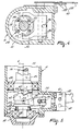
- Figure 2 represents a gearwheel housing 6 that can be fitted detachably under the spreading discs 3, as will be described with reference to Figure 3.
- the gearwheel housing 6 is provided at its lateral side with a flange 9 by means of which it can be fitted to a flange 10 of the frame tube 8.
- the drive shaft or intermediate shaft 7 extends from the central gearbox 5 through the frame tube 8.
- the gearwheel housing 6 comprises an outer casing 11 and a bottom 12.
- a gearwheel 13 that is fitted to the drive shaft or intermediate shaft 7.
- a central axis 14 whose centre line coincides with the centre line 4 of the spreading disc 3.
- the central axis is further fastened to the bottom 17 of the discharge spout 2 by means of a bolt 16.
- a support 18 and pins 19 the spreading disc 3 is fitted to the bottom 17.
- the central axis 14 is supported in a bearing 20 which is disposed in the bottom 12.
- a bushing 21 which is supported at its upper side by a bearing 22.
- the bushing 21 has a thickening 23 whose lower side is provided with four boreholes 24 that are orientated downwardly, the arrangement of the boreholes 24 being such that they are placed on a circular circumference at intervals of 90°.
- the thickening 23 is supported at its outer side by a bearing 25. All the bearings 15, 22 and 25 are supported in the outer casing 11. At its upper side the bushing 21 has a thickening 26 provided with a crown gear 27. Said crown gear 27 engages with the gearwheel 13.
- This bushing 28 is provided with a recess 29 having a circular inner circumference.
- the bushing 28 is provided with four pins 30 which are placed in an arrangement corresponding to that of the boreholes 24, i.e. on a circular circumference at intervals of 90°.
- the bushing 28 has an upwardly orientated groove 31 which is disposed around a key fitted to the axis 14, the arrangement being such that there is created a straight guide means for the bushing 28 along the axis 14 in a direction parallel to the centre line ( Figure 3).
- the pins 30 and the boreholes 24 extend parallel to the centre line, the arrangement being such that, when the bushing 28 is moved upwards and the pins 30 are located under the boreholes 24, the pins fit the boreholes.
- the bushing 28 is supported by a spring 32 that pushes the bushing upwards.
- a handle 38 On its outside the axis 37 is provided with a handle 38. If the handle 38 is pulled upwards, the pins 30, which are normally located in the boreholes 24 and are pulled into the boreholes by the spring 32, are pulled out of the boreholes 24, so that there is no longer a driving connection between the bottom 12 and the gearwheel 13. By means of a pin 39 the movement of the handle 38 can be blocked in two positions in one of the two apertures 40 of a blocking bracket 41.
- the implement operates as follows.
- the driving connection extends from the drive shaft or intermediary shaft 7 via the gearwheel 13, the crown gear 27 of the thickening 26, the bushing 21, the thickening 23, the boreholes 24, the pins 30, the bushing 28 with the projection 33, the axis 14 and the bolt 16, and is finally transferred to the spreading disc 3.
- the drive shaft 7 has to be stopped.
- the spreading disc 3 has to be rotated manually until the pins 30 come in front of the boreholes 24 and can be inserted therein. Thereafter the handle 38 with the pin 39 can be locked again.
- the handle 38 can be operated from the tractor. This is possible by hydraulic control of the arms, but also by electronic control. This is particularly advantageous if the further control of the implement, e.g. the adjustment of the slides and the outlets for the supply of fertilizer, can be effected electronically as well.
- Figure 5 shows another embodiment. Parts corresponding to those of the previous figures are designated by the same reference numerals.
- the upper side of the bushing 28 is not provided with pins, but with upwardly orientated claws 42.
- the thickening 23 is not provided with boreholes, but with claws 43 that correspond to the claws 42 and are orientated downwardly. In this manner, when the handle 38 is moved upwards, there is obtained a claw coupling.
- An advantage of this construction is that the claws, which have obliquely extending sides 44, automatically engage with each other when the flange 9 is put in rotation.
- gearwheel housing 6 including the activating device constituted inter alia by the adjustable bushing 28 with handle 38
- the gearwheel housing 6 including the activating device constituted inter alia by the adjustable bushing 28 with handle 38
- the spreading disc 3 is fastened to the axis 14 by means of the bolt 16
- the fastening of the gearwheel 13 to the shaft 7 is maintained, the apertures in the flanges 9 and 10 having such dimensions that the gearwheel can pass through. Accordingly, when the user of the implement does not have a need for a spreading disc that can be put out of operation, and wishes e.g. to use an other edge-spreading implement, it is possible to use an other gearwheel housing that is not provided with a coupling.
- the spreading disc 3 can be mounted, if desired, on the non-disengageable axis.
- the gearwheel housing is provided with a supply 45 for oil that is capable of being shut off, thus ensuring a proper lubrication of the gearwheels.
Landscapes
- Life Sciences & Earth Sciences (AREA)
- Soil Sciences (AREA)
- Environmental Sciences (AREA)
- Fertilizing (AREA)
Applications Claiming Priority (2)
| Application Number | Priority Date | Filing Date | Title |
|---|---|---|---|
| NL1008664 | 1998-03-20 | ||
| NL1008664A NL1008664C2 (nl) | 1998-03-20 | 1998-03-20 | Inrichting voor het verspreiden van materiaal. |
Publications (1)
| Publication Number | Publication Date |
|---|---|
| EP0943227A1 true EP0943227A1 (fr) | 1999-09-22 |
Family
ID=19766787
Family Applications (1)
| Application Number | Title | Priority Date | Filing Date |
|---|---|---|---|
| EP99200564A Withdrawn EP0943227A1 (fr) | 1998-03-20 | 1999-03-01 | Epandeur |
Country Status (2)
| Country | Link |
|---|---|
| EP (1) | EP0943227A1 (fr) |
| NL (1) | NL1008664C2 (fr) |
Families Citing this family (1)
| Publication number | Priority date | Publication date | Assignee | Title |
|---|---|---|---|---|
| CN107347311B (zh) * | 2017-08-10 | 2018-10-16 | 嵊州市林美生物科技有限公司 | 一种无污染新能源播种车 |
Citations (4)
| Publication number | Priority date | Publication date | Assignee | Title |
|---|---|---|---|---|
| EP0183292A1 (fr) * | 1984-10-29 | 1986-06-04 | C. van der Lely N.V. | Epandeur |
| DE8705460U1 (de) * | 1987-04-11 | 1987-07-02 | Accord-Landmaschinen Heinrich Weiste & Co Gmbh, 4770 Soest | Düngerstreuer |
| DE3919510A1 (de) * | 1989-06-15 | 1990-12-20 | Amazonen Werke Dreyer H | Zentrifugalduengerstreuer |
| FR2672577A1 (fr) * | 1991-02-08 | 1992-08-14 | Nodet Gougis | Distributeur de produits granules ou pulverulents a controle de debit integre. |
-
1998
- 1998-03-20 NL NL1008664A patent/NL1008664C2/nl not_active IP Right Cessation
-
1999
- 1999-03-01 EP EP99200564A patent/EP0943227A1/fr not_active Withdrawn
Patent Citations (5)
| Publication number | Priority date | Publication date | Assignee | Title |
|---|---|---|---|---|
| EP0183292A1 (fr) * | 1984-10-29 | 1986-06-04 | C. van der Lely N.V. | Epandeur |
| DE8705460U1 (de) * | 1987-04-11 | 1987-07-02 | Accord-Landmaschinen Heinrich Weiste & Co Gmbh, 4770 Soest | Düngerstreuer |
| EP0287006A1 (fr) | 1987-04-11 | 1988-10-19 | ACCORD Landmaschinen Heinrich Weiste & Co. GmbH | Epandeur d'engrais |
| DE3919510A1 (de) * | 1989-06-15 | 1990-12-20 | Amazonen Werke Dreyer H | Zentrifugalduengerstreuer |
| FR2672577A1 (fr) * | 1991-02-08 | 1992-08-14 | Nodet Gougis | Distributeur de produits granules ou pulverulents a controle de debit integre. |
Also Published As
| Publication number | Publication date |
|---|---|
| NL1008664C2 (nl) | 1999-09-21 |
Similar Documents
| Publication | Publication Date | Title |
|---|---|---|
| DE69601325T2 (de) | Rasenmäher | |
| DE3855589T2 (de) | Rasenmäher, dessen Benutzer hinterher läuft | |
| EP0307009B1 (fr) | Mécanisme inverseur | |
| DE60104492T2 (de) | Gehäuse für Rasenmäher | |
| DE8020306U1 (de) | Fahrbares bodenbehandlungsgeraet mit einer kupplung zwischen motor und raedern | |
| EP0808558B1 (fr) | Tondeuse cylindrique à râcleur pour le rouleau d'appui | |
| JPS62118804A (ja) | 耕うん草刈り装置 | |
| EP0943227A1 (fr) | Epandeur | |
| EP2011380A2 (fr) | Fraise à retournement destinée au traitement du sol | |
| AU767343B2 (en) | Power rate adjustment mechanism for a seeding implement | |
| JPH02126944A (ja) | 多目的破砕装置 | |
| US6082085A (en) | Foliage mowing implement having mechanical drive with main gearbox rotation | |
| US6367176B1 (en) | Rotary snow plow | |
| US6578349B2 (en) | Pivoting gearbox for rotary mower | |
| USRE32599E (en) | Drive reversing mechanism | |
| JP3436900B2 (ja) | 肥料散布機 | |
| JPH09262009A (ja) | 自走式施肥中耕機 | |
| CN213187113U (zh) | 田园管理机 | |
| US2890667A (en) | Fertilizer distributor gate operating arrangement | |
| EP2016815B1 (fr) | Appareil agricole | |
| EP0646676A2 (fr) | Dispositif d'entretien avec support réglable en hauteur pour une brosse cylindrique | |
| KR200219564Y1 (ko) | 트랙터용 감자 채취기 | |
| GB2026356A (en) | Forage harvester | |
| DE10325033B3 (de) | Antriebseinheit für eine Materialfördereinrichtung, insbesondere für ein Grasaufnahmefahrzeug | |
| JPH07213124A (ja) | 苗植付装置 |
Legal Events
| Date | Code | Title | Description |
|---|---|---|---|
| PUAI | Public reference made under article 153(3) epc to a published international application that has entered the european phase |
Free format text: ORIGINAL CODE: 0009012 |
|
| AK | Designated contracting states |
Kind code of ref document: A1 Designated state(s): DE DK FR GB NL |
|
| AX | Request for extension of the european patent |
Free format text: AL;LT;LV;MK;RO;SI |
|
| 17P | Request for examination filed |
Effective date: 20000229 |
|
| AKX | Designation fees paid |
Free format text: DE DK FR GB NL |
|
| 17Q | First examination report despatched |
Effective date: 20020328 |
|
| STAA | Information on the status of an ep patent application or granted ep patent |
Free format text: STATUS: THE APPLICATION IS DEEMED TO BE WITHDRAWN |
|
| 18D | Application deemed to be withdrawn |
Effective date: 20020808 |