EP0943432B1 - Druckzylinder mit einem Druckzylinderkern und einem auf ihn aufgeschobenen Druckzylindermantel - Google Patents
Druckzylinder mit einem Druckzylinderkern und einem auf ihn aufgeschobenen Druckzylindermantel Download PDFInfo
- Publication number
- EP0943432B1 EP0943432B1 EP19980103118 EP98103118A EP0943432B1 EP 0943432 B1 EP0943432 B1 EP 0943432B1 EP 19980103118 EP19980103118 EP 19980103118 EP 98103118 A EP98103118 A EP 98103118A EP 0943432 B1 EP0943432 B1 EP 0943432B1
- Authority
- EP
- European Patent Office
- Prior art keywords
- printing cylinder
- electrically conductive
- core
- printing
- threads
- Prior art date
- Legal status (The legal status is an assumption and is not a legal conclusion. Google has not performed a legal analysis and makes no representation as to the accuracy of the status listed.)
- Expired - Lifetime
Links
- 238000000034 method Methods 0.000 claims description 7
- 239000004033 plastic Substances 0.000 claims description 6
- 229920003023 plastic Polymers 0.000 claims description 6
- 239000003365 glass fiber Substances 0.000 claims description 5
- 239000002184 metal Substances 0.000 claims description 4
- 229910052751 metal Inorganic materials 0.000 claims description 4
- 229920002430 Fibre-reinforced plastic Polymers 0.000 claims description 3
- 239000011151 fibre-reinforced plastic Substances 0.000 claims description 3
- 238000009730 filament winding Methods 0.000 claims description 2
- 239000000463 material Substances 0.000 claims 3
- 238000009954 braiding Methods 0.000 claims 1
- 239000013013 elastic material Substances 0.000 claims 1
- 239000000835 fiber Substances 0.000 claims 1
- 230000002787 reinforcement Effects 0.000 claims 1
- 239000004020 conductor Substances 0.000 description 2
- RYGMFSIKBFXOCR-UHFFFAOYSA-N Copper Chemical compound [Cu] RYGMFSIKBFXOCR-UHFFFAOYSA-N 0.000 description 1
- 238000009825 accumulation Methods 0.000 description 1
- 230000006835 compression Effects 0.000 description 1
- 238000007906 compression Methods 0.000 description 1
- 238000011109 contamination Methods 0.000 description 1
- 229910052802 copper Inorganic materials 0.000 description 1
- 239000010949 copper Substances 0.000 description 1
- 239000000428 dust Substances 0.000 description 1
- 238000007786 electrostatic charging Methods 0.000 description 1
- 239000011152 fibreglass Substances 0.000 description 1
- 238000004519 manufacturing process Methods 0.000 description 1
- 239000002904 solvent Substances 0.000 description 1
- 238000004804 winding Methods 0.000 description 1
Images

Classifications
-
- B—PERFORMING OPERATIONS; TRANSPORTING
- B41—PRINTING; LINING MACHINES; TYPEWRITERS; STAMPS
- B41N—PRINTING PLATES OR FOILS; MATERIALS FOR SURFACES USED IN PRINTING MACHINES FOR PRINTING, INKING, DAMPING, OR THE LIKE; PREPARING SUCH SURFACES FOR USE AND CONSERVING THEM
- B41N6/00—Mounting boards; Sleeves Make-ready devices, e.g. underlays, overlays; Attaching by chemical means, e.g. vulcanising
-
- B—PERFORMING OPERATIONS; TRANSPORTING
- B41—PRINTING; LINING MACHINES; TYPEWRITERS; STAMPS
- B41F—PRINTING MACHINES OR PRESSES
- B41F13/00—Common details of rotary presses or machines
- B41F13/08—Cylinders
-
- B—PERFORMING OPERATIONS; TRANSPORTING
- B41—PRINTING; LINING MACHINES; TYPEWRITERS; STAMPS
- B41F—PRINTING MACHINES OR PRESSES
- B41F13/00—Common details of rotary presses or machines
- B41F13/08—Cylinders
- B41F13/193—Transfer cylinders; Offset cylinders
Definitions
- the invention relates to a printing cylinder with a printing cylinder core and a pressure cylinder jacket pushed onto it, which in the working position the pressure cylinder core sits frictionally and from a seamless inner layer made of fiber-reinforced plastic and an electrical one attached to it conductive material existing seamless outer layer with defined External shape exists.
- Such a pressure cylinder is known from DE 27 00 118 C2.
- the pressure cylinder jacket can be expanded by means of a gas cushion which is attached to the Surface of the pressure cylinder core by supplying compressed gas through a Supply line is established.
- the impression cylinder jacket has a seamless inner layer from one fiber-reinforced plastic and one of a vulcanized on it electrically conductive rubber or a hardened rubber-like Plastic existing seamless outer layer that defines a has cylindrical outer shape.
- These known printing cylinders have the Disadvantage that they are electrically up and possibly during the printing process discharge what sparks and fires - in most cases solvent-containing atmospheres in the vicinity of printing presses - as well Contamination caused by dust accumulation.
- the object of the invention is a pressure cylinder of a known type to improve that none during the printing process train electrical charges.
- electrically conductive threads are arranged such that at least one Make an electrically conductive connection with the metallic Printing cylinder core and at least in one place with the elastic there is electrically conductive material of the impression cylinder jacket.
- the invention on the one hand an electrostatic charging of the Pressure cylinder and thus the risk of fire prevented and on the other hand one higher mechanical strength, especially of the pressure cylinder jacket and thus also the printing cylinder as a whole, which increases the Print quality and service life leads.
- the embodiment of a printing cylinder 1 shown in Fig. 1 exists from a metal cylinder 2 and a Printing cylinder jacket 3.
- the printing cylinder jacket 3 consists of a fiber-reinforced electrically conductive inner layer 4 and one thereon applied elastic outer layer 3a made of electrically conductive rubber or a rubbery plastic.
- the elastic layer 3a can in Depending on the printing process also as a base for the application of a Serve printing form.
- the printing cylinder core 2 can not only cylindrical, but also be conical.
- a Compressed air connection 5 compressed air in the hollow pressure cylinder core 2 which from in Compression cylinder core 2 provided compressed air outlets 6, whereby the Pressure cylinder jacket 3 expanded and axially by the resulting air cushion completely pushed into its working position or removed can be.
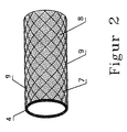
- the 2 is an embodiment of one - preferably by individual Glass fibers - fiber-reinforced inner layer 4 shown in a plastic 8.
- the plastic 8 with the glass fibers are electrically conductive threads embedded, especially metal threads - especially copper - which preferably are intersecting and form a network.
- the threads 7 of the Braid are at least at some crossing points 9 with each other electrically conductively connected.
- the braid from the threads 7 can also be used as be designed to be relatively rigid. Through the electrically conductive braid electrostatic charges of the printing cylinder 1 avoided during the printing process.
Landscapes
- Engineering & Computer Science (AREA)
- Mechanical Engineering (AREA)
- Printing Plates And Materials Therefor (AREA)
Description
- Fig. 1
- einen Druckzylinder in Seitenansicht mit teilweisem Schnitt in schematischer Darstelluung,
- Fig. 2
- eine nahtlose faserverstärkte Innenschicht für einen Druckzylinder in schematischer Darstellung.
Claims (6)
- Druckzylinder (1) mit einem metallischen Druckzylinderkern (2) und einem auf ihn aufgeschobenen Druckzylindermantel (3), der in Arbeitsstellung auf dem Druckzylinderkern (2) reibschlüssig sitzt und aus einer nahtlosen Innenschicht (4) aus einem faserverstärktem Kunststoff und einer darauf aufgebrachten elektrisch leitfähigen aus einem elastischen Material bestehenden nahtlosen Außenschicht (3a) mit definierter Außenform besteht, dadurch gekennzeichnet, daß in der Innenschicht (4) elektrisch leitfähige Fäden derart angeordnet sind, daß mindestens an einer Stelle eine elektrisch leitende Verbindung mit dem Druckzylinderkern (2) und mindestens an einer Stelle eine elektrisch leitende Verbindung mit der elektrisch leitfähigen elastischen Schicht (3a) des Druckzylindermantels (3) besteht.
- Druckzylinder nach Anspruch 1, dadurch gekennzeichnet, daß die Fäden sich kreuzend geflechtartig angeordnet sind, und mindestens an einem Teil ihrer Kreuzungsstellen elektrisch leitend miteinander verbunden sind.
- Druckzylinder nach Anspruch 1 oder 2, dadurch gekennzeichnet, daß die Fäden aus einem Metall bestehen.
- Druckzylinder nach einem der Ansprüche 1 bis 3, dadurch gekennzeichnet, daß die Faserverstärkung in Form einzelner Fasern im Filament-Winding-Verfahren kontinuierlich in den Kunststoff (8) der Innenschicht (4) eingebracht ist.
- Druckzylinder nach Anspruch 4, dadurch gekennzeichnet, daß die einzelnen Fasern Glasfasern sind.
- Druckzylinder nach einem der Ansprüche 1 bis 5, dadurch gekennzeichnet, daß die elektrisch leitfähige elastische Schicht (3a) aus Gummi oder einem gummiartigen Kunststoff besteht.
Priority Applications (2)
| Application Number | Priority Date | Filing Date | Title |
|---|---|---|---|
| DE59802053T DE59802053D1 (de) | 1998-02-23 | 1998-02-23 | Druckzylinder mit einem Druckzylinderkern und einem auf ihn aufgeschobenen Druckzylindermantel |
| EP19980103118 EP0943432B1 (de) | 1998-02-23 | 1998-02-23 | Druckzylinder mit einem Druckzylinderkern und einem auf ihn aufgeschobenen Druckzylindermantel |
Applications Claiming Priority (1)
| Application Number | Priority Date | Filing Date | Title |
|---|---|---|---|
| EP19980103118 EP0943432B1 (de) | 1998-02-23 | 1998-02-23 | Druckzylinder mit einem Druckzylinderkern und einem auf ihn aufgeschobenen Druckzylindermantel |
Publications (2)
| Publication Number | Publication Date |
|---|---|
| EP0943432A1 EP0943432A1 (de) | 1999-09-22 |
| EP0943432B1 true EP0943432B1 (de) | 2001-11-07 |
Family
ID=8231468
Family Applications (1)
| Application Number | Title | Priority Date | Filing Date |
|---|---|---|---|
| EP19980103118 Expired - Lifetime EP0943432B1 (de) | 1998-02-23 | 1998-02-23 | Druckzylinder mit einem Druckzylinderkern und einem auf ihn aufgeschobenen Druckzylindermantel |
Country Status (2)
| Country | Link |
|---|---|
| EP (1) | EP0943432B1 (de) |
| DE (1) | DE59802053D1 (de) |
Families Citing this family (4)
| Publication number | Priority date | Publication date | Assignee | Title |
|---|---|---|---|---|
| DE10243183C1 (de) * | 2002-03-19 | 2003-08-21 | Polywest Kunststofftechnik | Hülse für den Flexodruck |
| DE10261955A1 (de) * | 2002-03-19 | 2003-11-13 | Polywest Kunststofftechnik | Hülse für den Flexodruck |
| DE20204412U1 (de) | 2002-03-19 | 2002-05-29 | Polywest Kunststofftechnik Saueressig & Partner GmbH & Co. KG, 48683 Ahaus | Hülse für den Flexodruck |
| JP2015501742A (ja) | 2011-12-09 | 2015-01-19 | フリント、グループ、ジャーマニー、ゲゼルシャフト、ミット、ベシュレンクテル、ハフツング | 印刷工業で用いられるガラス繊維強化スリーブ |
Family Cites Families (9)
| Publication number | Priority date | Publication date | Assignee | Title |
|---|---|---|---|---|
| US3235772A (en) * | 1961-08-08 | 1966-02-15 | Gurin Emanuel | Anti-static printer's blanket in combination with grounded metal roller |
| JPS55164858A (en) * | 1979-06-12 | 1980-12-22 | Fuji Xerox Co Ltd | Heat fixing device |
| GB2051681B (en) * | 1979-06-25 | 1983-03-02 | Drg Ltd | Printing rolls |
| DE3401350C2 (de) * | 1984-01-17 | 1986-01-23 | M.A.N.- Roland Druckmaschinen AG, 6050 Offenbach | Zylinderaufzug für einen Gummizylinder einer Offsetrotationsdruckmaschine |
| ES2022212B3 (es) * | 1987-06-19 | 1991-12-01 | Saueressig Gmbh + Co | Cilindro de huecograbado consistiendo en un nucleo y un manguito soltable unido con dicho nucleo |
| DE4230431C2 (de) * | 1992-09-11 | 1996-09-26 | Roland Man Druckmasch | Offset-Gummituchhülse |
| EP0741016A3 (de) * | 1995-05-05 | 1997-09-24 | Pretto De Escher Wyss Srl | Presswalze |
| US5907998A (en) * | 1995-12-29 | 1999-06-01 | Howard W. Demoore | Anti-static, anti-smearing pre-stretched and pressed flat, precision-cut striped flexible coverings for transfer cylinders |
| DE19634033C1 (de) * | 1996-08-23 | 1998-03-26 | Knut Dr Ing Bauer | Druckzylinder mit einem Druckzylinderkern und einem auf ihn aufgeschobenen Druckzylindermantel |
-
1998
- 1998-02-23 EP EP19980103118 patent/EP0943432B1/de not_active Expired - Lifetime
- 1998-02-23 DE DE59802053T patent/DE59802053D1/de not_active Expired - Fee Related
Also Published As
| Publication number | Publication date |
|---|---|
| EP0943432A1 (de) | 1999-09-22 |
| DE59802053D1 (de) | 2001-12-13 |
Similar Documents
| Publication | Publication Date | Title |
|---|---|---|
| EP0819550B1 (de) | Gummizylinderhülse, insbesondere für Offset-Rollenrotationsdruckmaschinen | |
| DE10259593B4 (de) | Vorrichtung und Verfahren zum Beflechten eines Kerns | |
| EP0594986B1 (de) | Offset-Gummituchhülse | |
| DE2951629A1 (de) | Antriebswelle aus faserverstaerktem kunststoff, mit verlorenem dorn und festgewickelten endstuecken | |
| DE3643073A1 (de) | Luftfeder | |
| DE102011104071A1 (de) | Blattfeder und Verfahren zu deren Herstellung | |
| EP0196443B1 (de) | Tiefdruckzylinder, bestehend aus einem Kern und einer lösbar mit diesem verbundenen Hülse | |
| EP0406172A2 (de) | Vorrichtung zum Aufbringen einer weichelastischen Schicht auf Walzen für graphische Maschinen | |
| EP0655561A1 (de) | Mit Fasern verstärkte Kunststoffwalze mit Rautierung | |
| DE202014003409U1 (de) | Führungswalze eines Einzugswalzenpaares einer Granuliervorrichtung | |
| EP1110748B1 (de) | Gummituch mit isotroper Verstärkungsschicht | |
| EP0943432B1 (de) | Druckzylinder mit einem Druckzylinderkern und einem auf ihn aufgeschobenen Druckzylindermantel | |
| EP1001831B1 (de) | Rohr sowie golfschläger mit schaft aus diesem rohr | |
| DE2731509A1 (de) | Endloses druckband fuer drehverstellbare gummistempel | |
| EP1177100B1 (de) | Dehnschicht aus kompressiblem material | |
| WO2005090075A2 (de) | Hülse für druckmaschinen | |
| DE19634033C1 (de) | Druckzylinder mit einem Druckzylinderkern und einem auf ihn aufgeschobenen Druckzylindermantel | |
| DE3408295C1 (de) | Kette aus nichtmetallischen Werkstoffen und Verfahren zu ihrer Herstellung | |
| EP1551631B1 (de) | Rakel, insbesondere für den siebdruck | |
| EP1004455A2 (de) | Hülse aus thermisch verformbaren Materialien sowie Verfahren zu deren Herstellung | |
| EP2274156B1 (de) | Verfahren zur herstellung einer walze für die bearbeitung bandförmigen materiales und nach diesem verfahren hergestellte walze | |
| DE10243183C1 (de) | Hülse für den Flexodruck | |
| DE102013212228B4 (de) | Schlauchrollbalg | |
| EP1346846A2 (de) | Hülse für den Flexodruck | |
| DE102019218125B3 (de) | Verfahren zum formschlüssigen Verbinden eines stabförmigen Körpers aus faserverstärktem Kunststoff mit einem Metallkörper |
Legal Events
| Date | Code | Title | Description |
|---|---|---|---|
| PUAI | Public reference made under article 153(3) epc to a published international application that has entered the european phase |
Free format text: ORIGINAL CODE: 0009012 |
|
| AK | Designated contracting states |
Kind code of ref document: A1 Designated state(s): CH DE DK FR GB IT LI NL SE |
|
| AX | Request for extension of the european patent |
Free format text: AL;LT;LV;MK;RO;SI |
|
| 17P | Request for examination filed |
Effective date: 20000322 |
|
| AKX | Designation fees paid |
Free format text: CH DE DK FR GB IT LI NL SE |
|
| GRAG | Despatch of communication of intention to grant |
Free format text: ORIGINAL CODE: EPIDOS AGRA |
|
| 17Q | First examination report despatched |
Effective date: 20001215 |
|
| GRAG | Despatch of communication of intention to grant |
Free format text: ORIGINAL CODE: EPIDOS AGRA |
|
| GRAH | Despatch of communication of intention to grant a patent |
Free format text: ORIGINAL CODE: EPIDOS IGRA |
|
| GRAH | Despatch of communication of intention to grant a patent |
Free format text: ORIGINAL CODE: EPIDOS IGRA |
|
| RAP1 | Party data changed (applicant data changed or rights of an application transferred) |
Owner name: FGM FRITZ GRADERT MASCHINENBAU GMBH & CO. KG |
|
| RIN1 | Information on inventor provided before grant (corrected) |
Inventor name: BAUER, KNUT, DR. Inventor name: SCHERF, JEANETTE |
|
| GRAA | (expected) grant |
Free format text: ORIGINAL CODE: 0009210 |
|
| AK | Designated contracting states |
Kind code of ref document: B1 Designated state(s): CH DE DK FR GB IT LI NL SE |
|
| PG25 | Lapsed in a contracting state [announced via postgrant information from national office to epo] |
Ref country code: NL Free format text: LAPSE BECAUSE OF FAILURE TO SUBMIT A TRANSLATION OF THE DESCRIPTION OR TO PAY THE FEE WITHIN THE PRESCRIBED TIME-LIMIT Effective date: 20011107 Ref country code: IT Free format text: LAPSE BECAUSE OF FAILURE TO SUBMIT A TRANSLATION OF THE DESCRIPTION OR TO PAY THE FEE WITHIN THE PRESCRIBED TIME-LIMIT;WARNING: LAPSES OF ITALIAN PATENTS WITH EFFECTIVE DATE BEFORE 2007 MAY HAVE OCCURRED AT ANY TIME BEFORE 2007. THE CORRECT EFFECTIVE DATE MAY BE DIFFERENT FROM THE ONE RECORDED. Effective date: 20011107 Ref country code: GB Free format text: LAPSE BECAUSE OF FAILURE TO SUBMIT A TRANSLATION OF THE DESCRIPTION OR TO PAY THE FEE WITHIN THE PRESCRIBED TIME-LIMIT Effective date: 20011107 Ref country code: FR Free format text: LAPSE BECAUSE OF FAILURE TO SUBMIT A TRANSLATION OF THE DESCRIPTION OR TO PAY THE FEE WITHIN THE PRESCRIBED TIME-LIMIT Effective date: 20011107 |
|
| REG | Reference to a national code |
Ref country code: CH Ref legal event code: EP |
|
| REF | Corresponds to: |
Ref document number: 59802053 Country of ref document: DE Date of ref document: 20011213 |
|
| REG | Reference to a national code |
Ref country code: GB Ref legal event code: IF02 |
|
| PG25 | Lapsed in a contracting state [announced via postgrant information from national office to epo] |
Ref country code: SE Free format text: LAPSE BECAUSE OF FAILURE TO SUBMIT A TRANSLATION OF THE DESCRIPTION OR TO PAY THE FEE WITHIN THE PRESCRIBED TIME-LIMIT Effective date: 20020207 Ref country code: DK Free format text: LAPSE BECAUSE OF FAILURE TO SUBMIT A TRANSLATION OF THE DESCRIPTION OR TO PAY THE FEE WITHIN THE PRESCRIBED TIME-LIMIT Effective date: 20020207 |
|
| PG25 | Lapsed in a contracting state [announced via postgrant information from national office to epo] |
Ref country code: LI Free format text: LAPSE BECAUSE OF NON-PAYMENT OF DUE FEES Effective date: 20020228 Ref country code: CH Free format text: LAPSE BECAUSE OF NON-PAYMENT OF DUE FEES Effective date: 20020228 |
|
| NLV1 | Nl: lapsed or annulled due to failure to fulfill the requirements of art. 29p and 29m of the patents act | ||
| GBV | Gb: ep patent (uk) treated as always having been void in accordance with gb section 77(7)/1977 [no translation filed] |
Effective date: 20011107 |
|
| PG25 | Lapsed in a contracting state [announced via postgrant information from national office to epo] |
Ref country code: DE Free format text: LAPSE BECAUSE OF NON-PAYMENT OF DUE FEES Effective date: 20020903 |
|
| EN | Fr: translation not filed | ||
| PLBE | No opposition filed within time limit |
Free format text: ORIGINAL CODE: 0009261 |
|
| STAA | Information on the status of an ep patent application or granted ep patent |
Free format text: STATUS: NO OPPOSITION FILED WITHIN TIME LIMIT |
|
| REG | Reference to a national code |
Ref country code: CH Ref legal event code: PL |
|
| 26N | No opposition filed |