EP0943916A2 - Verfahren und Vorrichtung zur Prüfung von Gegenständen - Google Patents
Verfahren und Vorrichtung zur Prüfung von Gegenständen Download PDFInfo
- Publication number
- EP0943916A2 EP0943916A2 EP99301695A EP99301695A EP0943916A2 EP 0943916 A2 EP0943916 A2 EP 0943916A2 EP 99301695 A EP99301695 A EP 99301695A EP 99301695 A EP99301695 A EP 99301695A EP 0943916 A2 EP0943916 A2 EP 0943916A2
- Authority
- EP
- European Patent Office
- Prior art keywords
- article
- vessel
- enclosed volume
- heating fluid
- passages
- Prior art date
- Legal status (The legal status is an assumption and is not a legal conclusion. Google has not performed a legal analysis and makes no representation as to the accuracy of the status listed.)
- Granted
Links
Images
Classifications
-
- G—PHYSICS
- G01—MEASURING; TESTING
- G01N—INVESTIGATING OR ANALYSING MATERIALS BY DETERMINING THEIR CHEMICAL OR PHYSICAL PROPERTIES
- G01N25/00—Investigating or analyzing materials by the use of thermal means
- G01N25/72—Investigating presence of flaws
Definitions
- the present invention relates generally to a method and an apparatus for inspecting articles.
- the invention is particularly suitable for inspecting impingement cooling passages, or film cooling passages, of hollow turbine blades or hollow turbine vanes of gas turbine engines to determine whether such cooling passages are blocked or if they are in an incorrect position.
- the invention is also suitable for inspecting articles to determine whether there are cracks, debonds, voids, delaminations, oxidation or corrosion in the article and also if there is insufficient adhesion between the article and a coating on the article.
- the turbine blades and turbine vanes of gas turbine engines usually comprise cooling passages for single or multi pass convection cooling, impingement cooling or film cooling purposes.
- the film cooling passages extend through the wall of the turbine blade from a first, interior, surface to a second, exterior, surface of the turbine blade.
- the impingement cooling passages extend through structure within the turbine blade and are spaced from the first, interior, surface of the turbine blade.
- the convection cooling passages generally extend longitudinally in the wall of the turbine blade.
- Other cooling passages extend through structure within the turbine blade.
- the turbine blades and turbine vanes may comprise various combinations of any one or ore of convection cooling passages, impingement cooling passages and film cooling passages.
- turbine blades and turbine vanes are cast using the investment casting technique in which ceramic cores, located in ceramic shell moulds, are used to define the impingement cooling passages and other cooling passages within the structure of the turbine blade.
- the film cooling passages are generally formed by machining through the walls of the turbine blades to connect with other cooling passages within the structure of the turbine blade.
- a subsequently formed film cooling passage interconnecting with the other cooling passage may only graze or even miss the other cooling passage, it may interconnect at the wrong position or the tool, may pass across the other cooling passage and damage the opposite wall of the other cooling passage. These effects may reduce the strength of the turbine blade and are difficult to detect. Thus it is desirable to detect any discrepancies in the impingement and/or other cooling passages before the film cooling passages are formed by expensive machining processes.
- borescopes It is known to use borescopes to inspect the interior of cast turbine blades and turbine vanes to ensure that the cooling passages have been correctly formed.
- borescopes is a time consuming and labour intensive process.
- it has the disadvantage of not being able to detect some specific forms of blockage unless specific lighting techniques or light guides are used.
- thermography it is also known to use thermography to inspect turbine blades to determine if the cooling passages are blocked.
- US patent US3566669 passes a hot gas through and out of the cooling passages of a turbine blade and through and out of a reference passage having different wall thicknesses.
- An infrared camera views the external surface of the turbine blade and the reference passage to determine if the cooling passages are at the correct position relative to the outer surface of the wall and/ or to determine if any of the cooling passages are blocked.
- UK patent GB2164746B passes a hot gas through the film cooling passages of a turbine blade.
- An infrared camera views the film cooling passages and determines the relative intensities of the black body radiation emitted by the film cooling passages to determine if any of the film cooling passages are blocked.
- US patent US5111046 is similar to GB2164746B but subsequently passes a cold gas through the film cooling passages of the turbine blade to determine the presence of certain type of blockage.
- the present invention seeks to provide a method of inspecting an article which reduces the above mentioned problems.
- the present invention provides a method of inspecting an article, the article having a first surface and a second surface facing in the opposite direction to the first surface, comprising the steps of:-
- the method comprises injecting a small quantity of the condensable heating fluid into the enclosed volume after step (a) and before step (b).
- the method may comprise injecting a small quantity of the condensed heating fluid into the enclosed volume after step (a) and before step (b).
- step (c) comprises supplying steam to the enclosed volume.
- Step (e) may comprises applying a thermochromic material to the second surface of the article and viewing the second surface of the article with a camera sensitive to radiation in the visible light band.
- Step (e) may comprise viewing the second surface of the article with a video camera, a cine camera or a CCD camera.
- step (e) comprises viewing the second surface of the article with a camera sensitive to radiation in the infra red band.
- a calibrated emissivity coating may be applied to the second surface of the article.
- step (d) comprises directing a plurality of jets of the condensable heating fluid onto the first surface of the article.
- step (a) comprises forming the enclosed volume solely by the first surface of the article.
- step (d) comprises directing a plurality of jets of the condensable heating fluid through passages in the article onto the first surface of the article.
- step (b) comprises evacuating the enclosed volume.
- the article is a turbine blade or a turbine vane.
- step (a) may comprise forming the enclosed volume partially with a vessel.
- Step (d) may comprises supplying a plurality of jets of the condensable heating fluid through passages in the vessel onto the first surface of the article.
- the article may be a composite material article, a laminated material article or a coated article.
- the present invention also provides a method of inspecting an article, the article having a plurality of passages extending from a first surface to a second surface facing in the opposite direction to the first surface, comprising the steps of:-
- the method comprises injecting a small quantity of the condensable heating fluid into the enclosed volume after step (a) and before step (b).
- the method comprises injecting a small quantity of the condensed heating fluid into the enclosed volume after step (a) and before step (b).
- step (c) comprises supplying steam to the enclosed volume.
- Step (e) may comprise applying a thermochromic material to the second surface of the article and viewing the second surface of the vessel with a camera sensitive to radiation in the visible light band.
- step (e) comprises viewing the second surface of the vessel with a video camera, a cine camera or a CCD camera.
- step (e) may comprise viewing the second surface of the vessel with a camera sensitive to radiation in the infra red band.
- a calibrated emissivity coating may be applied to the second surface of the vessel.
- step (d) comprises directing a plurality of jets of the condensable heating fluid onto the first surface of the vessel.
- step (d) comprises directing a plurality of jets of the condensable heating fluid through passages in the article onto the first surface of the vessel.
- step (b) comprises evacuating the enclosed volume.
- the article is a turbine blade or a turbine vane.
- the present invention also provides an apparatus for inspecting an article, the article having a first surface and a second surface facing in the opposite direction to the first surface, the first surface at least partially defining an enclosed volume, comprising means to remove air from the enclosed volume, means to supply a condensable heating fluid to the enclosed volume, means to direct a flow of the condensable heating fluid onto or over the first surface of the article to cause the temperature of the first surface to change, means to view the second surface of the article during the temperature change to produce a series of images, and means to analyse the series of images to determine the presence or absence of defects in the article.
- the present invention also provides an apparatus for inspecting an article, the article having a plurality of passages extending from a first surface to a second surface facing in the opposite direction to the first surface, comprising a vessel having a first surface to define an enclosed volume with the second surface of the article, means to remove air from the enclosed volume, means to supply a condensable heating fluid to the enclosed volume, means to direct a flow of the condensable heating fluid onto or over the first surface of the vessel to cause the temperature of the first surface to change, means to view the second surface of the article during the temperature change to produce a series of images, and means to analyse the series of images to determine the presence or absence of defects in the article.
- the means to supply a condensable heating fluid comprises a supply of steam.
- the second surface of the article, or the second surface of the vessel may have a thermochromic material.
- the means to view the second surface of the article, or the second surface of the vessel may comprise a camera sensitive to radiation in the visible light band.
- the means to view the second surface of the article, or the second surface of the vessel may comprise a video camera, a cine camera or a CCD camera.
- the means to view the second surface of the article, or the second surface of the vessel comprises a camera sensitive to radiation in the infra red band.
- the second surface of the article, or second surface of the vessel may have a calibrated emissivity coating.
- the enclosed volume is defined solely by the first surface of the article.
- the article comprises a plurality of passages to direct a plurality of jets of the condensable heating fluid onto the first surface of the article.
- the article may comprise a plurality of passages to direct a plurality of jets of the condensable heating fluid onto the first surface of the vessel.
- the article is a turbine blade or a turbine vane.
- the enclosed volume is defined by the first surface of the article and a first surface of a vessel.
- the vessel may comprise a plurality of passages to direct a plurality of jets of the condensable heating fluid onto the first surface of the article.
- the means to remove gas from the enclosed volume comprises means to evacuate the enclosed volume.
- the article may be a composite material article, a laminated material article or a coated article.
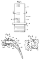
- Figure 1 is a view of a gas turbine blade.
- Figure 2 is an enlarged cross-sectional view in the direction of arrows A-A through the gas turbine blade shown in figure 1.
- Figure 3 is a further enlarged portion of part of figure 2.
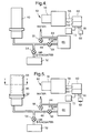
- Figure 4 is an apparatus for inspecting an article according to the present invention.
- Figure 5 is another apparatus for inspecting an article according to the present invention.
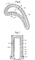
- Figure 6 is a enlarged cross-sectional view through the article and part of the apparatus in the direction of arrows Y-Y in figure 5.
- Figure 7 is a cross-sectional view in the direction of arrows Z-Z in figure 6.
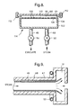
- Figure 8 is a further apparatus for inspecting an article according to the present invention.
- Figure 9 is a cross-sectional view through a pipe shown in figure 4.
- a turbine blade 10 as shown in figures 1 to 3, comprises a root portion 12, a shank portion 14, a platform portion 16 and an aerofoil portion 18.
- the turbine blade 10 is suitable for use in a gas turbine engine (not shown).
- the aerofoil portion 18 has a number of lengthwise extending chambers 20, 22, 24, 26 and 28.
- the chamber 20 is adjacent the trailing edge of the aerofoil portion 18 and the chamber 30 is adjacent the leading edge of the aerofoil portion 18.
- the aerofoil portion 18 of the turbine blade 10 has a first, inner, surface 30 and a second, outer, surface 32.
- the inner surface 30 defines the chamber 26.
- the second surface 32 has a pressure surface 32A and a suction surface 32B.
- the chamber 26 is the main chamber and there are a plurality of further chambers 34 which are narrow relative to the main chamber 26 which surround the main chamber 26 and which are positioned between the first surface 30 and the second surface 32.
- the chambers 34 also extend lengthwise of the aerofoil portion 18.
- Each of the chambers 34 is interconnected with the main chamber 26 by one or more cooling passages 36.
- the chambers 34 between the chamber 26 and the pressure surface 32A are interconnected to the pressure surface 32A by one or more film cooling passages 38.
- the chambers 34 have first, inner, surfaces 35 adjacent the second, outer, surface 32 of the aerofoil portion 38.
- cooling air is forced up the chambers 34 adjacent the suction surface 32B of the aerofoil portion 18 from the root portion 12.
- the cooling air then flows through the cooling passages 36 into and across the main chamber 26.
- the cooling air then flows from the main chamber 26 through the cooling passages 36 into the chambers 34 adjacent the pressure surface 32A.
- the cooling air flowing through the cooling passages 36 impinges upon the first surfaces 35 of the chamber 34 to provide impingement cooling of the wall of the aerofoil portion 18.
- the cooling air then flows through the film cooling passages 38 to exit the aerofoil portion 18 and to provide a cooling film of air on the pressure surface 32A of the aerofoil portion 18.
- the turbine blades 10 are generally manufactured by investment casting using ceramic shell moulds and ceramic cores to define the chambers 20, 22, 24, 26 and 28, the further chambers 34 and the passages 36. After the metal has been cast in the ceramic shell mould the ceramic shell mould and ceramic cores are removed.
- the passages 38 are generally produced by electrochemical machining, electodischarge machining or laser machining etc.
- the apparatus 42 comprises a supply of steam 46, for example a boiler, which is supplied with water via a pipe 44.
- the supply of steam 46 is interconnected to the main chamber 26 in the aerofoil portion 18 of the as cast turbine blade 40 via a pipe 48.
- the pipe 48 has a valve 50 to control the supply of steam along the pipe 48 to the chamber 26.
- the pipe 44 is also interconnected to the chamber 26 via the pipe 48 and the pipe 48 has a valve 55 to control the supply of water along the pipe 48 to the chamber 26.
- a vacuum pump 52 is also interconnected to the main chamber 26 in the aerofoil portion 18 of the as cast turbine blade 40 via the pipe 48.
- a valve 54 is provided to control the removal of gas from the chamber 26.
- a camera 56 is provided to view the second, outer, surface 32 of the aerofoil portion 18 of the as cast turbine blade 40.
- the camera 56 supplies electrical image signals along line 58 to a processor 60, which comprises an image recorder 62 and an image analyser 64.
- the processor 60 supplies electrical signals along line 66 to an indicator 68 and/or along line 70 to a display 72.
- the processor 60 may comprise a personal computer or other computer.
- the indicator 68 may for example comprise a lamp which lights to indicate that the passages 36 in the as cast turbine blade 40 are present and are in the correct position.
- the display 72 may be a television screen, or monitor to show the images of the as cast turbine blade 40 to an operator.
- the camera 56 is preferably a camera sensitive to radiation in the infrared band, but the camera 56 may be a camera sensitive to radiation in the visible band if the turbine blade 40 is coated with a thermochromic material, for example a paint, or coating, which contains thermochromic liquid crystals or a self adhesive tape having thermochromic liquid crystals.
- the camera may be a thermal imaging camera, a video camera, a cine camera or a CCD camera.
- the pipe 48 is fitted and sealed to the portion of the chamber 26 in the root portion 12 of the turbine blade 40. Initially all of the valves 54, 55 and 56 are closed.
- the turbine blade 40 and camera 56 are so arranged to enable one surface of the turbine blade 40 to be viewed by the camera 56, in particular the turbine blade 40 may be mounted in a fixture (not shown).
- valve 54 When the turbine blade 40 is connected to the pipe 48 and the chamber 26 is sealed, the valve 54 is opened to allow the vacuum pump to evacuate the chamber 26 and hence the chambers 34 and cooling passages 36, assuming the chambers 34 and cooling passages 36 have been correctly formed. After the chamber 26 has been evacuated the valve 54 is closed and the valve 50 is opened to allow steam to be supplied to the chamber 26. As the steam is admitted to the chamber 26 the temperature of the second surface 32 of the turbine blade 40 is viewed by the camera 56 and recorded by the image recorder 62 of the processor 60. The analyser 64 of the processor 60 analyses the images of the stored in the image recorder 62 to determine whether the turbine blade 40 is satisfactory or not.
- the steam flows through the chamber 26 and some of the steam flows through the cooling passages 36 and the steam impinges on the first surfaces 35 of the chambers 34, in the form of discrete jets.
- the first surfaces 35 of the chambers 34 are those adjacent the second surface 32 of the aerofoil portion 18 of the turbine blade 40.
- Each jet of steam creates a very localised condensing heat transfer to the wall of the turbine blade 40 which in turn generates a thermal wave that passes through the thickness of the wall.
- Each thermal wave creates a transient hot spot on the second surface 32 of the aerofoil portion 18 of the turbine blade 40, the region around each transient hot spot heats up more slowly to the same temperature as the transient hot spot.
- the camera 56 is arranged to view the second surface 32 of the aerofoil portion 18 of the turbine blade 40 to detect the transient hot spots on the surface 32 of the aerofoil portion 18 of the turbine blade 40.
- the presence of transient hot spots at the appropriate positions in the images of the aerofoil portion 18 of the turbine blade 40 indicates that the cooling passages 36 have been correctly formed.
- the lack of transient hot spots at the appropriate positions, or transient hot spots at unexpected positions, in the images of the aerofoil portion 18 of the turbine blade 40 indicates that the cooling passages 36 have been incorrectly formed.
- the turbine blades 40 with incorrectly formed cooling passages 36 may be discarded before any more expensive machining processes are performed.
- the processor 60 sends appropriate signals to the display 68 to show whether a particular turbine blade 40 has correctly or incorrectly formed cooling passages 36. If the thermal diffusivity of the material of the turbine blade 40 is known a time:temperature history of a transient hot spot enables the processor 60 to determine the local wall thickness of the aerofoil 18, or if the thickness is known the thermal diffusivity may be calculated.
- the use of steam to heat the turbine blade 40 is advantageous because it provides the condensing heat transfer to the turbine blade 40.
- the condensation of the steam in the chambers 34, when the steam from the cooling passages 36 contacts the wall, allows more steam to be drawn into the chambers 34 from the chamber 26 to create impingement jets of steam which produce significant flow of heat into the wall of the aerofoil portion 18.
- impingement jets of steam occur until the pressure ratio across the cooling passages 36 falls below a critical value.
- the critical value depends upon the geometry of the chamber 34 and the cooling passages 36.
- the pressure ratio may fall due to a decrease in pressure in chamber 26 or an increase in pressure in chamber 34.
- the above method may be modified by firstly opening the valve 50 to allow a small quantity of steam into the chamber 26 which will condense on the walls of the chambers 26 and 34 to form a film of water.
- the valve 50 is then closed and valve 54 is opened to evacuate the chambers 26 and 34.
- the film of water in the chambers 26 and 34 evaporates at low pressure displacing the gas, or air, during the evacuation process.
- Air is a non-condensable gas, which inhibits the flow of the impingement jets of steam onto the surface of the wall, and may reduce the rate of heat transfer.
- the small quantity of steam also heats up the root portion 12 and the shank portion 14 of the turbine blade 10 through which the steam has to flow to reach the chambers 34 and cooling passages 36.
- the heating up of the root portion 12 and shank portion 14 by the steam reduces the amount of condensation occurring in the chambers 34 and cooling passages 36.
- the above method may be modified by firstly opening the valve 55 to allow a small quantity of water into the chamber 26.
- the valve 55 is then closed and valve 54 is opened to evacuate the chambers 26 and 34.
- the water in the chambers 26 and 34 evaporates at low pressure displacing the gas, or air, during the evacuation process.
- the aerofoil portion 18 is cooled, for example by a flow of cool gas, to enable transient hot spots with a large temperature difference from the surrounding regions to be produced.
- the cooling is performed quickly to minimise the possibility of cooling the root portion 12 and the shank portion 14 of the turbine blade 10.
- the pipe 48 preferably comprises a thick outer wall 47 to contain the steam pressure and a thin inner wall 49 of low thermal mass and low thermal conductivity to separate the flow of steam from the thick outer wall 47, which is at ambient, room, temperature.
- the thin inner wall 49 quickly heats up when steam flows through the pipe 48 so minimising the amount of condensation which is drawn into turbine blade 10.
- the pipe 48 includes a steam trap chamber 51 to prevent condensate, which has formed on the thick outer wall 47, from entering the chamber 26 of the turbine blade 40.
- the steam flowing through the inner pipe 49 flows radially outwardly into the chamber 51 to prevent condensate on the outer pipe 47 flowing into the turbine blade 40.
- a further steam pipe 53, or other heating apparatus, is positioned in proximity to the chamber 51 and pipe 48 to minimise condensation of steam.
- the turbine blade may be coated with an emissivity coating to assist the resolution of transient hot spots or to provide a calibrated emissivity surface to allow accurate measurement of the temperature to be made.
- the advantage of the present invention is that it allows the cooling passages 36 of the turbine blade 40 to perform their required function, but under different circumstances.
- the present invention also allows the turbine blades be inspected more quickly than using a borescope or X-ray computer tomography.
- the present invention uses evacuation and condensation heating to create a very high rate of temperature increase on the inside of the turbine blade unlike conventional thermography which uses hot gases which have a very low rate of temperature increase.
- the advantage of the very high rate of temperature increase is that it makes it possible to resolve smaller features, i.e. the impingement cooling holes.
- the present invention does not require a flow of the steam through and out of the turbine blade unlike conventional thermography, enabling the turbine blade to be inspected before all their cooling passages have been formed and thus enables defective turbine blades to be rejected before being subjected to expensive machining processes. It is also possible to determine the distance of hot spots from datum features on the turbine blades for each individual turbine blade. This information may be used in subsequent machining processes to guide the machining process to eliminate the problem of machining film cooling holes in turbine blades in a position which is incompatible with the actual position of the internal cooling passages, thus saving on scrap and eliminating the need for further inspection.
- thermochromic liquid crystals and a video camera sensitive to radiation in the visible band is particularly suitable for low volumes of turbine blades, and an inspector may view each image of a recording made by the video camera, this avoids the expense of a thermal imaging camera.
- thermochromic liquid crystals and a CCD camera sensitive to radiation in the visible band is particularly suitable for moderate volumes of turbine blades and qualitative inspection only is required, a processor is preferred to analyse the images made by the CCD camera.
- thermochromic liquid crystals The use of a camera sensitive to radiation in the infrared band is particularly suitable for high volumes of turbine blades, to eliminate the expense of the thermochromic liquid crystals.
- a non-calibrated emissivity coating may be applied to the turbine blades. If quantitative information is required a calibrated emissivity coating is applied to the turbine blades.
- An apparatus 82 for inspecting turbine blades 86 is shown in figure 5, 6 and 7.
- the apparatus 82 is substantially the same as the apparatus 42 but differs because the turbine blades 86 have film cooling passages 92 extending through the wall of the turbine blades 86 from a chamber 90.
- the apparatus 80 differs in that a vessel 84, having an aerofoil shape in cross-section, is placed over the aerofoil portion of the turbine blade 86.
- the vessel 84 is spaced from the wall of the turbine blade 86 by a uniform clearance 88 to define an enclosed volume between the vessel 84 and the wall of the turbine blade 86.
- the open end of the vessel 84 is sealed to the platform portion of the turbine blade 86 by a seal strip 82.
- the pipe 48 is arranged to interconnect with the chamber 90.
- the process of inspecting the turbine blade 86 is the same as that described with reference to figure 4, however the steam flows through the film cooling passages 92 as a plurality of impingement jets which impinge upon the first, inner, surface 83 of the vessel 84.
- the camera 56 is arranged to view the second, outer, surface 85 of the vessel 84, to detect transient hot spots on the outer surface 85 of the vessel 84.
- the apparatus 114 is substantially the same as the apparatus 42 but differs because the article 100 is not a turbine blade, is not hollow and does not have film cooling passages extending through the article 100.
- the apparatus 114 differs in that a vessel 102 is placed over the article 100.
- the interior of the vessel 102 is divided into a first chamber 104 and a second chamber 110 by a plate 106.
- the plate 106 is spaced from the article 100 by a uniform clearance 110 to define the second chamber 110 between the plate 106 and the article 100.
- the open end of the vessel 114 is sealed to the article 100 by one or more clamps and/or seals 112.
- the plate 106 is provided with a plurality of passages 108 to direct jets of steam onto a first surface 99 of the article 100.
- the pipe 48 is arranged to interconnect with the first chamber 104 for the supply of steam to the first chamber 104.
- a pipe 49 is arranged to interconnect with the first chamber 104 for the evacuation of the first chamber 104.
- a camera is arranged to view the second surface 101 of the article 100.
- the process of inspecting the article 100 is the same as that described with reference to figure 4, however the steam flows through the plurality of passages 108 as impingement jets which impinge upon the first surface 99 of the article 100.
- the camera is arranged to view the second surface 101 of the vessel 100 to detect transient hot spots on the second surface 101 of the article 100.
- the technique is used in this embodiment to detect variations in the thermal diffusivity in the article 100 and hence to detect defects in the article 100, for example voids, cracks, areas of corrosion or areas of oxidation. If the article is a composite or laminated material the technique may detect areas with debonds or delaminations. If the article has a coating the technique may detect areas with poor adhesion of the coating.
- the resolution may be achieved by increasing the number of passages 108 per unit area in the plate 106.
- the invention has described the use of jets of steam directed to impinge upon the surface of the article or vessel to provide impingement heat transfer to the article or vessel, it may be possible to arrange for the steam to flow over the surface of the article if the surface of the article has other heat transferring features on its first, inner, surface such as ribs, strips, pedestals. These features will transfer heat into the wall of the turbine blade to create hot spots on the second, outer, surface of the aerofoil portion of the turbine blade.
Landscapes
- Physics & Mathematics (AREA)
- Health & Medical Sciences (AREA)
- Life Sciences & Earth Sciences (AREA)
- Chemical & Material Sciences (AREA)
- Analytical Chemistry (AREA)
- Biochemistry (AREA)
- General Health & Medical Sciences (AREA)
- General Physics & Mathematics (AREA)
- Immunology (AREA)
- Pathology (AREA)
- Investigating Or Analyzing Materials Using Thermal Means (AREA)
- Turbine Rotor Nozzle Sealing (AREA)
Applications Claiming Priority (2)
| Application Number | Priority Date | Filing Date | Title |
|---|---|---|---|
| GB9805861 | 1998-03-20 | ||
| GBGB9805861.3A GB9805861D0 (en) | 1998-03-20 | 1998-03-20 | A method and an apparatus for inspecting articles |
Publications (3)
| Publication Number | Publication Date |
|---|---|
| EP0943916A2 true EP0943916A2 (de) | 1999-09-22 |
| EP0943916A3 EP0943916A3 (de) | 2001-11-28 |
| EP0943916B1 EP0943916B1 (de) | 2008-04-09 |
Family
ID=10828854
Family Applications (1)
| Application Number | Title | Priority Date | Filing Date |
|---|---|---|---|
| EP99301695A Expired - Lifetime EP0943916B1 (de) | 1998-03-20 | 1999-03-08 | Verfahren zur Inspektion von Turbinenschaufeln |
Country Status (4)
| Country | Link |
|---|---|
| US (1) | US6153889A (de) |
| EP (1) | EP0943916B1 (de) |
| DE (1) | DE69938470T2 (de) |
| GB (1) | GB9805861D0 (de) |
Cited By (9)
| Publication number | Priority date | Publication date | Assignee | Title |
|---|---|---|---|---|
| EP1494020A1 (de) * | 2003-06-30 | 2005-01-05 | Siemens Westinghouse Power Corporation | Verfahren und Vorrichtung zum on-line Messen einer Störung in Wärmedämmschichten einer Turbine |
| GB2473099A (en) * | 2009-08-27 | 2011-03-02 | Rolls Royce Plc | Inspection of holes in a component situated within an engine |
| GB2487930A (en) * | 2011-02-09 | 2012-08-15 | Rolls Royce Plc | Inspection of engine components |
| US8587660B2 (en) | 2010-07-30 | 2013-11-19 | General Electric Company | Image recording assemblies and coupling mechanisms for stator vane inspection |
| US8602722B2 (en) | 2010-02-26 | 2013-12-10 | General Electric Company | System and method for inspection of stator vanes |
| EP2998418A1 (de) * | 2014-09-18 | 2016-03-23 | Rolls-Royce plc | Verfahren zum bearbeiten eines gasturbinenmotorbauteils |
| EP3626388A1 (de) * | 2018-09-21 | 2020-03-25 | United Technologies Corporation | Verfahren zur formung von kühllöchern |
| EP3647534A1 (de) * | 2018-11-05 | 2020-05-06 | General Electric Company | Motorkomponentenleistungsinspektionshülse und verfahren zur inspektion einer motorkomponente |
| CN119901702A (zh) * | 2023-10-26 | 2025-04-29 | 中国石油天然气股份有限公司 | 蒸汽裂解产物在线近红外光谱分析装置及分析方法 |
Families Citing this family (47)
| Publication number | Priority date | Publication date | Assignee | Title |
|---|---|---|---|---|
| US6711506B2 (en) * | 2001-11-21 | 2004-03-23 | Computerized Thermal Imaging, Inc. | Computerized operator assistance for turbine component inspection |
| US7140047B2 (en) * | 2003-08-12 | 2006-11-28 | Ronald Kronenberger | Headwear piece with magnetic accessory holding assembly |
| US7255534B2 (en) * | 2004-07-02 | 2007-08-14 | Siemens Power Generation, Inc. | Gas turbine vane with integral cooling system |
| US7489811B2 (en) * | 2004-10-08 | 2009-02-10 | Siemens Energy, Inc. | Method of visually inspecting turbine blades and optical inspection system therefor |
| US8137611B2 (en) * | 2005-03-17 | 2012-03-20 | Siemens Energy, Inc. | Processing method for solid core ceramic matrix composite airfoil |
| US20070132898A1 (en) * | 2005-11-04 | 2007-06-14 | Union College | Light transmission based liquid crystal temperature sensor |
| US7300242B2 (en) * | 2005-12-02 | 2007-11-27 | Siemens Power Generation, Inc. | Turbine airfoil with integral cooling system |
| US7432505B2 (en) * | 2006-05-04 | 2008-10-07 | Siemens Power Generation, Inc. | Infrared-based method and apparatus for online detection of cracks in steam turbine components |
| US7671338B2 (en) * | 2006-06-14 | 2010-03-02 | Meyer Tool, Inc. | Apparatus and method for analyzing relative outward flow characterizations of fabricated features |
| DE102009034796A1 (de) * | 2009-07-25 | 2011-02-24 | Man Diesel & Turbo Se | Verfahren zum Installieren von Funktionsüberwachungsmitteln in einer Strömungsmaschinenanlage |
| GB201001354D0 (en) * | 2010-01-28 | 2010-03-17 | Rolls Royce Plc | An apparatus and a method of determining the presence of an alumina layer on a component |
| WO2012003372A2 (en) * | 2010-06-30 | 2012-01-05 | Newman John W | Method and apparatus for the remote nondestructive evaluation of an object |
| US10704958B2 (en) | 2010-10-21 | 2020-07-07 | Siemens Energy, Inc. | Method for monitoring a high-temperature region of interest in a turbine engine |
| DE102011009403B4 (de) * | 2011-01-25 | 2015-02-05 | Deutsches Zentrum für Luft- und Raumfahrt e.V. | Messverfahren für Wärmeübertragungskennwerte von Porenmaterialien |
| US20120224048A1 (en) * | 2011-03-03 | 2012-09-06 | Trzcinski Frank J | Portable boroscope for inspecting turbomachine blades |
| US8553233B2 (en) | 2011-06-30 | 2013-10-08 | John W. Newman | Method and apparatus for the remote nondestructive evaluation of an object using shearography image scale calibration |
| US8792705B2 (en) | 2011-11-03 | 2014-07-29 | United Technologies Corporation | System and method for automated defect detection utilizing prior data |
| US8744166B2 (en) | 2011-11-03 | 2014-06-03 | United Technologies Corporation | System and method for multiple simultaneous automated defect detection |
| US8761490B2 (en) | 2011-11-03 | 2014-06-24 | United Technologies Corporation | System and method for automated borescope inspection user interface |
| US8781209B2 (en) | 2011-11-03 | 2014-07-15 | United Technologies Corporation | System and method for data-driven automated borescope inspection |
| US9471057B2 (en) * | 2011-11-09 | 2016-10-18 | United Technologies Corporation | Method and system for position control based on automated defect detection feedback |
| US8781210B2 (en) | 2011-11-09 | 2014-07-15 | United Technologies Corporation | Method and system for automated defect detection |
| US8861673B2 (en) | 2011-11-30 | 2014-10-14 | United Technologies Corporation | Component aperture location using computed tomography |
| DE102011056052A1 (de) * | 2011-12-05 | 2013-06-06 | Krones Ag | Vorrichtung zur Verarbeitung eines Lebensmittelprodukts, bevorzugt zur Herstellung und/oder Abfüllung von Getränken, Komponente für eine solche Vorrichtung sowie Verfahren zur thermischen Überwachung von Komponenten |
| US9330449B2 (en) | 2013-03-15 | 2016-05-03 | Digital Wind Systems, Inc. | System and method for ground based inspection of wind turbine blades |
| US9453500B2 (en) | 2013-03-15 | 2016-09-27 | Digital Wind Systems, Inc. | Method and apparatus for remote feature measurement in distorted images |
| US9395337B2 (en) | 2013-03-15 | 2016-07-19 | Digital Wind Systems, Inc. | Nondestructive acoustic doppler testing of wind turbine blades from the ground during operation |
| US9194843B2 (en) | 2013-03-15 | 2015-11-24 | Digital Wind Systems, Inc. | Method and apparatus for monitoring wind turbine blades during operation |
| US20160252420A1 (en) | 2013-10-18 | 2016-09-01 | United Technologies Corporation | Method and assembly for inspecting engine component |
| US10048133B2 (en) | 2014-03-07 | 2018-08-14 | United Technologies Corporation | Thermal inspection system |
| GB2550582B (en) * | 2016-05-23 | 2020-07-15 | Bluedrop Medical Ltd | A skin inspection device identifying abnormalities |
| US11397112B2 (en) | 2017-01-09 | 2022-07-26 | General Electric Company | System and method for monitoring of gas turbine components with infrared system |
| US11193820B2 (en) | 2017-01-09 | 2021-12-07 | General Electric Company | System and method for disposable infrared imaging system |
| US10928362B2 (en) | 2018-05-04 | 2021-02-23 | Raytheon Technologies Corporation | Nondestructive inspection using dual pulse-echo ultrasonics and method therefor |
| US10902664B2 (en) | 2018-05-04 | 2021-01-26 | Raytheon Technologies Corporation | System and method for detecting damage using two-dimensional imagery and three-dimensional model |
| US11079285B2 (en) | 2018-05-04 | 2021-08-03 | Raytheon Technologies Corporation | Automated analysis of thermally-sensitive coating and method therefor |
| US10958843B2 (en) | 2018-05-04 | 2021-03-23 | Raytheon Technologies Corporation | Multi-camera system for simultaneous registration and zoomed imagery |
| US10914191B2 (en) | 2018-05-04 | 2021-02-09 | Raytheon Technologies Corporation | System and method for in situ airfoil inspection |
| US11268881B2 (en) | 2018-05-04 | 2022-03-08 | Raytheon Technologies Corporation | System and method for fan blade rotor disk and gear inspection |
| US10473593B1 (en) | 2018-05-04 | 2019-11-12 | United Technologies Corporation | System and method for damage detection by cast shadows |
| US10685433B2 (en) | 2018-05-04 | 2020-06-16 | Raytheon Technologies Corporation | Nondestructive coating imperfection detection system and method therefor |
| US10488371B1 (en) | 2018-05-04 | 2019-11-26 | United Technologies Corporation | Nondestructive inspection using thermoacoustic imagery and method therefor |
| US10943320B2 (en) | 2018-05-04 | 2021-03-09 | Raytheon Technologies Corporation | System and method for robotic inspection |
| US11002638B2 (en) * | 2019-03-22 | 2021-05-11 | Raytheon Technologies Corporation | Multi-zone automatic magnetoscop inspection system |
| CN112362689B (zh) * | 2020-11-02 | 2022-02-18 | 浙江大学 | 一种基于热色液晶的冷凝传热瞬态测量装置及方法 |
| CN112747863B (zh) * | 2020-12-02 | 2023-04-21 | 江苏大洋海洋装备有限公司 | 一种海洋废旧装备损伤检测修复再利用装置 |
| CN117074423B (zh) * | 2023-10-16 | 2023-12-12 | 江苏图恩视觉科技有限公司 | 一种薄膜缺陷检测系统及其工作方法 |
Family Cites Families (12)
| Publication number | Priority date | Publication date | Assignee | Title |
|---|---|---|---|---|
| US3439525A (en) * | 1966-12-28 | 1969-04-22 | Boeing Co | Nondestructive testing method using liquid crystals |
| US3566669A (en) * | 1968-09-04 | 1971-03-02 | Harry Parker | Method and apparatus for thermally examining fluid passages in a body |
| US3700903A (en) * | 1970-12-09 | 1972-10-24 | Zenith Radio Corp | Optical detecting systems for sensing variations in the lateral motion of light rays |
| JPS60186743A (ja) * | 1984-03-06 | 1985-09-24 | Mitsubishi Heavy Ind Ltd | 構造物内部欠陥検査方法及び装置 |
| US4644162A (en) * | 1984-09-20 | 1987-02-17 | General Electric Company | Cooling hole inspection |
| GB2283538B (en) * | 1984-12-01 | 1995-09-13 | Rolls Royce | Air cooled gas turbine aerofoil |
| US5111046A (en) * | 1991-03-18 | 1992-05-05 | General Electric Company | Apparatus and method for inspecting cooling holes |
| US5246340A (en) * | 1991-11-19 | 1993-09-21 | Allied-Signal Inc. | Internally cooled airfoil |
| US6116776A (en) * | 1995-03-28 | 2000-09-12 | Somerset Technical Laboratories Ltd. | Method and apparatus for detecting irregularities on or in the wall of a vessel |
| US5683181A (en) * | 1995-05-12 | 1997-11-04 | Thermal Wave Imaging, Inc. | Method and apparatus for enhancing thermal wave imaging of reflective low-emissivity solids |
| US5625196A (en) * | 1995-05-30 | 1997-04-29 | Abb Industrial Systems, Inc. | Method and apparatus for monitoring/calibrating a process measuring system |
| JPH09217990A (ja) * | 1996-02-09 | 1997-08-19 | Daido Steel Co Ltd | 水冷式中空体における冷却状況検査方法 |
-
1998
- 1998-03-20 GB GBGB9805861.3A patent/GB9805861D0/en not_active Ceased
-
1999
- 1999-03-08 EP EP99301695A patent/EP0943916B1/de not_active Expired - Lifetime
- 1999-03-08 DE DE69938470T patent/DE69938470T2/de not_active Expired - Lifetime
- 1999-03-12 US US09/266,817 patent/US6153889A/en not_active Expired - Lifetime
Cited By (16)
| Publication number | Priority date | Publication date | Assignee | Title |
|---|---|---|---|---|
| EP1494020A1 (de) * | 2003-06-30 | 2005-01-05 | Siemens Westinghouse Power Corporation | Verfahren und Vorrichtung zum on-line Messen einer Störung in Wärmedämmschichten einer Turbine |
| EP1804056A3 (de) * | 2003-06-30 | 2008-10-29 | Siemens Power Generation, Inc. | Verfahren und Vorrichtung zur Online-Messung von Defekten bei Turbinenwärmedämmschichten |
| EP2154518A3 (de) * | 2003-06-30 | 2010-03-17 | Siemens Energy, Inc. | Verfahren und Vorrichtung zur Online-Messung von Defekten bei Turbinenwärmedämmschichten |
| GB2473099A (en) * | 2009-08-27 | 2011-03-02 | Rolls Royce Plc | Inspection of holes in a component situated within an engine |
| GB2473099B (en) * | 2009-08-27 | 2012-04-18 | Rolls Royce Plc | Inspection of holes |
| US8215159B2 (en) | 2009-08-27 | 2012-07-10 | Rolls-Royce Plc | Inspection of holes |
| US8602722B2 (en) | 2010-02-26 | 2013-12-10 | General Electric Company | System and method for inspection of stator vanes |
| US8587660B2 (en) | 2010-07-30 | 2013-11-19 | General Electric Company | Image recording assemblies and coupling mechanisms for stator vane inspection |
| GB2487930A (en) * | 2011-02-09 | 2012-08-15 | Rolls Royce Plc | Inspection of engine components |
| EP2998418A1 (de) * | 2014-09-18 | 2016-03-23 | Rolls-Royce plc | Verfahren zum bearbeiten eines gasturbinenmotorbauteils |
| US9809886B2 (en) | 2014-09-18 | 2017-11-07 | Rolls-Royce Plc | Method of machining a gas turbine engine component |
| EP3626388A1 (de) * | 2018-09-21 | 2020-03-25 | United Technologies Corporation | Verfahren zur formung von kühllöchern |
| US11000925B2 (en) | 2018-09-21 | 2021-05-11 | Raytheon Technologies Corporation | Method of forming cooling holes |
| EP3647534A1 (de) * | 2018-11-05 | 2020-05-06 | General Electric Company | Motorkomponentenleistungsinspektionshülse und verfahren zur inspektion einer motorkomponente |
| US11340184B2 (en) | 2018-11-05 | 2022-05-24 | General Electric Company | Engine component performance inspection sleeve and method of inspecting engine component |
| CN119901702A (zh) * | 2023-10-26 | 2025-04-29 | 中国石油天然气股份有限公司 | 蒸汽裂解产物在线近红外光谱分析装置及分析方法 |
Also Published As
| Publication number | Publication date |
|---|---|
| EP0943916A3 (de) | 2001-11-28 |
| US6153889A (en) | 2000-11-28 |
| DE69938470D1 (de) | 2008-05-21 |
| EP0943916B1 (de) | 2008-04-09 |
| DE69938470T2 (de) | 2008-07-10 |
| GB9805861D0 (en) | 1998-05-13 |
Similar Documents
| Publication | Publication Date | Title |
|---|---|---|
| US6153889A (en) | Method and an apparatus for inspecting articles | |
| EP2339333B1 (de) | Wärmeinspektionssystem | |
| US11504813B2 (en) | Methods for health monitoring of ceramic matrix composite components in gas turbine engines | |
| US20180027190A1 (en) | Infrared non-destructive evaluation of cooling holes using evaporative membrane | |
| US5773790A (en) | Beam blocking material and method for beam drilling and inspecting cooling holes | |
| US7909507B2 (en) | Thermal inspection system and method | |
| US10685433B2 (en) | Nondestructive coating imperfection detection system and method therefor | |
| EP0934795B1 (de) | In-Situ Reparaturverfahren für ein Turbomaschinenbauteil. | |
| EP2354783B1 (de) | Wärmeinspektionssystem und Verfahren mit externem Durchfluss | |
| AU2003252931B2 (en) | Steam turbine system inspecting method | |
| US20100247330A1 (en) | Liner in a cooling channel of a turbine blade | |
| Naryzhnyy et al. | Additively Manufactured Guide Vane With Integral Measurement System for Validation on Engine | |
| US11673188B2 (en) | Method for removing refractory metal cores | |
| CN113567492A (zh) | 一种基于红外热耗散的涡轮叶片热障涂层无损检测方法和检测装置 | |
| Traxler et al. | Pulsed thermography inspection of the target elements for the W7-X divertor | |
| Abidin et al. | Effect of Temperature on Penetration of Test Liquid into Boiler Pipe | |
| WO2025247646A1 (en) | Inspection systems for gas turbine components and methods | |
| JP2004339944A (ja) | ガスタービンのモニタリング装置および方法 | |
| Chaudhry et al. | Thermographic Quality Assurance of Turbine Engine Components | |
| OZEKI et al. | ICOPE-15-1072 Development of Nondestructive Testing Method for TBC Delamination of Gas Turbine | |
| Russell et al. | Detection, Location, and Classification of Space Shuttle Main Engine Nozzle Leaks by Transient Thermographic Inspection |
Legal Events
| Date | Code | Title | Description |
|---|---|---|---|
| PUAI | Public reference made under article 153(3) epc to a published international application that has entered the european phase |
Free format text: ORIGINAL CODE: 0009012 |
|
| AK | Designated contracting states |
Kind code of ref document: A2 Designated state(s): AT BE CH CY DE DK ES FI FR GB GR IE IT LI LU MC NL PT SE Kind code of ref document: A2 Designated state(s): CH DE FR GB LI SE |
|
| AX | Request for extension of the european patent |
Free format text: AL;LT;LV;MK;RO;SI |
|
| PUAL | Search report despatched |
Free format text: ORIGINAL CODE: 0009013 |
|
| AK | Designated contracting states |
Kind code of ref document: A3 Designated state(s): AT BE CH CY DE DK ES FI FR GB GR IE IT LI LU MC NL PT SE |
|
| AX | Request for extension of the european patent |
Free format text: AL;LT;LV;MK;RO;SI |
|
| 17P | Request for examination filed |
Effective date: 20011109 |
|
| AKX | Designation fees paid |
Free format text: CH DE FR GB LI SE |
|
| 17Q | First examination report despatched |
Effective date: 20040525 |
|
| 17Q | First examination report despatched |
Effective date: 20040525 |
|
| 17Q | First examination report despatched |
Effective date: 20040525 |
|
| GRAP | Despatch of communication of intention to grant a patent |
Free format text: ORIGINAL CODE: EPIDOSNIGR1 |
|
| RTI1 | Title (correction) |
Free format text: METHOD OF INSPECTING TURBINE BLADES |
|
| GRAS | Grant fee paid |
Free format text: ORIGINAL CODE: EPIDOSNIGR3 |
|
| GRAA | (expected) grant |
Free format text: ORIGINAL CODE: 0009210 |
|
| AK | Designated contracting states |
Kind code of ref document: B1 Designated state(s): CH DE FR GB LI SE |
|
| REG | Reference to a national code |
Ref country code: GB Ref legal event code: FG4D |
|
| REG | Reference to a national code |
Ref country code: CH Ref legal event code: EP |
|
| REF | Corresponds to: |
Ref document number: 69938470 Country of ref document: DE Date of ref document: 20080521 Kind code of ref document: P |
|
| REG | Reference to a national code |
Ref country code: SE Ref legal event code: TRGR |
|
| REG | Reference to a national code |
Ref country code: CH Ref legal event code: NV Representative=s name: KIRKER & CIE S.A. |
|
| ET | Fr: translation filed | ||
| PLBE | No opposition filed within time limit |
Free format text: ORIGINAL CODE: 0009261 |
|
| STAA | Information on the status of an ep patent application or granted ep patent |
Free format text: STATUS: NO OPPOSITION FILED WITHIN TIME LIMIT |
|
| 26N | No opposition filed |
Effective date: 20090112 |
|
| PGFP | Annual fee paid to national office [announced via postgrant information from national office to epo] |
Ref country code: GB Payment date: 20130327 Year of fee payment: 15 Ref country code: FR Payment date: 20130405 Year of fee payment: 15 Ref country code: DE Payment date: 20130327 Year of fee payment: 15 Ref country code: CH Payment date: 20130325 Year of fee payment: 15 Ref country code: SE Payment date: 20130327 Year of fee payment: 15 |
|
| REG | Reference to a national code |
Ref country code: DE Ref legal event code: R119 Ref document number: 69938470 Country of ref document: DE |
|
| REG | Reference to a national code |
Ref country code: CH Ref legal event code: PL |
|
| REG | Reference to a national code |
Ref country code: SE Ref legal event code: EUG |
|
| GBPC | Gb: european patent ceased through non-payment of renewal fee |
Effective date: 20140308 |
|
| PG25 | Lapsed in a contracting state [announced via postgrant information from national office to epo] |
Ref country code: SE Free format text: LAPSE BECAUSE OF NON-PAYMENT OF DUE FEES Effective date: 20140309 |
|
| REG | Reference to a national code |
Ref country code: FR Ref legal event code: ST Effective date: 20141128 |
|
| REG | Reference to a national code |
Ref country code: DE Ref legal event code: R119 Ref document number: 69938470 Country of ref document: DE Effective date: 20141001 |
|
| PG25 | Lapsed in a contracting state [announced via postgrant information from national office to epo] |
Ref country code: CH Free format text: LAPSE BECAUSE OF NON-PAYMENT OF DUE FEES Effective date: 20140331 Ref country code: FR Free format text: LAPSE BECAUSE OF NON-PAYMENT OF DUE FEES Effective date: 20140331 Ref country code: DE Free format text: LAPSE BECAUSE OF NON-PAYMENT OF DUE FEES Effective date: 20141001 Ref country code: GB Free format text: LAPSE BECAUSE OF NON-PAYMENT OF DUE FEES Effective date: 20140308 Ref country code: LI Free format text: LAPSE BECAUSE OF NON-PAYMENT OF DUE FEES Effective date: 20140331 |