EP0945612B1 - Kraftstoffeinspritzventil für eine Brennkraftmaschine - Google Patents
Kraftstoffeinspritzventil für eine Brennkraftmaschine Download PDFInfo
- Publication number
- EP0945612B1 EP0945612B1 EP98121774A EP98121774A EP0945612B1 EP 0945612 B1 EP0945612 B1 EP 0945612B1 EP 98121774 A EP98121774 A EP 98121774A EP 98121774 A EP98121774 A EP 98121774A EP 0945612 B1 EP0945612 B1 EP 0945612B1
- Authority
- EP
- European Patent Office
- Prior art keywords
- fuel
- injection hole
- reservoir
- fuel reservoir
- width
- Prior art date
- Legal status (The legal status is an assumption and is not a legal conclusion. Google has not performed a legal analysis and makes no representation as to the accuracy of the status listed.)
- Expired - Lifetime
Links
- 239000000446 fuel Substances 0.000 title claims description 330
- 238000002485 combustion reaction Methods 0.000 title claims description 54
- 238000002347 injection Methods 0.000 claims description 241
- 239000007924 injection Substances 0.000 claims description 241
- 238000003825 pressing Methods 0.000 claims description 5
- 239000007921 spray Substances 0.000 description 39
- 230000000052 comparative effect Effects 0.000 description 15
- 238000011144 upstream manufacturing Methods 0.000 description 9
- 239000006185 dispersion Substances 0.000 description 8
- 230000006835 compression Effects 0.000 description 6
- 238000007906 compression Methods 0.000 description 6
- 238000003466 welding Methods 0.000 description 4
- 230000015572 biosynthetic process Effects 0.000 description 3
- 230000001419 dependent effect Effects 0.000 description 1
- 238000011161 development Methods 0.000 description 1
- 230000018109 developmental process Effects 0.000 description 1
- 238000009826 distribution Methods 0.000 description 1
- 238000004519 manufacturing process Methods 0.000 description 1
- 238000004080 punching Methods 0.000 description 1
Images



Classifications
-
- F—MECHANICAL ENGINEERING; LIGHTING; HEATING; WEAPONS; BLASTING
- F02—COMBUSTION ENGINES; HOT-GAS OR COMBUSTION-PRODUCT ENGINE PLANTS
- F02M—SUPPLYING COMBUSTION ENGINES IN GENERAL WITH COMBUSTIBLE MIXTURES OR CONSTITUENTS THEREOF
- F02M61/00—Fuel-injectors not provided for in groups F02M39/00 - F02M57/00 or F02M67/00
- F02M61/16—Details not provided for in, or of interest apart from, the apparatus of groups F02M61/02 - F02M61/14
- F02M61/18—Injection nozzles, e.g. having valve seats; Details of valve member seated ends, not otherwise provided for
- F02M61/1806—Injection nozzles, e.g. having valve seats; Details of valve member seated ends, not otherwise provided for characterised by the arrangement of discharge orifices, e.g. orientation or size
- F02M61/184—Discharge orifices having non circular sections
-
- F—MECHANICAL ENGINEERING; LIGHTING; HEATING; WEAPONS; BLASTING
- F02—COMBUSTION ENGINES; HOT-GAS OR COMBUSTION-PRODUCT ENGINE PLANTS
- F02M—SUPPLYING COMBUSTION ENGINES IN GENERAL WITH COMBUSTIBLE MIXTURES OR CONSTITUENTS THEREOF
- F02M61/00—Fuel-injectors not provided for in groups F02M39/00 - F02M57/00 or F02M67/00
- F02M61/16—Details not provided for in, or of interest apart from, the apparatus of groups F02M61/02 - F02M61/14
- F02M61/18—Injection nozzles, e.g. having valve seats; Details of valve member seated ends, not otherwise provided for
-
- F—MECHANICAL ENGINEERING; LIGHTING; HEATING; WEAPONS; BLASTING
- F02—COMBUSTION ENGINES; HOT-GAS OR COMBUSTION-PRODUCT ENGINE PLANTS
- F02M—SUPPLYING COMBUSTION ENGINES IN GENERAL WITH COMBUSTIBLE MIXTURES OR CONSTITUENTS THEREOF
- F02M61/00—Fuel-injectors not provided for in groups F02M39/00 - F02M57/00 or F02M67/00
- F02M61/16—Details not provided for in, or of interest apart from, the apparatus of groups F02M61/02 - F02M61/14
- F02M61/18—Injection nozzles, e.g. having valve seats; Details of valve member seated ends, not otherwise provided for
- F02M61/1806—Injection nozzles, e.g. having valve seats; Details of valve member seated ends, not otherwise provided for characterised by the arrangement of discharge orifices, e.g. orientation or size
- F02M61/1833—Discharge orifices having changing cross sections, e.g. being divergent
-
- F—MECHANICAL ENGINEERING; LIGHTING; HEATING; WEAPONS; BLASTING
- F02—COMBUSTION ENGINES; HOT-GAS OR COMBUSTION-PRODUCT ENGINE PLANTS
- F02M—SUPPLYING COMBUSTION ENGINES IN GENERAL WITH COMBUSTIBLE MIXTURES OR CONSTITUENTS THEREOF
- F02M61/00—Fuel-injectors not provided for in groups F02M39/00 - F02M57/00 or F02M67/00
- F02M61/16—Details not provided for in, or of interest apart from, the apparatus of groups F02M61/02 - F02M61/14
- F02M61/18—Injection nozzles, e.g. having valve seats; Details of valve member seated ends, not otherwise provided for
- F02M61/1853—Orifice plates
-
- F—MECHANICAL ENGINEERING; LIGHTING; HEATING; WEAPONS; BLASTING
- F02—COMBUSTION ENGINES; HOT-GAS OR COMBUSTION-PRODUCT ENGINE PLANTS
- F02B—INTERNAL-COMBUSTION PISTON ENGINES; COMBUSTION ENGINES IN GENERAL
- F02B75/00—Other engines
- F02B75/12—Other methods of operation
- F02B2075/125—Direct injection in the combustion chamber for spark ignition engines, i.e. not in pre-combustion chamber
-
- Y—GENERAL TAGGING OF NEW TECHNOLOGICAL DEVELOPMENTS; GENERAL TAGGING OF CROSS-SECTIONAL TECHNOLOGIES SPANNING OVER SEVERAL SECTIONS OF THE IPC; TECHNICAL SUBJECTS COVERED BY FORMER USPC CROSS-REFERENCE ART COLLECTIONS [XRACs] AND DIGESTS
- Y02—TECHNOLOGIES OR APPLICATIONS FOR MITIGATION OR ADAPTATION AGAINST CLIMATE CHANGE
- Y02T—CLIMATE CHANGE MITIGATION TECHNOLOGIES RELATED TO TRANSPORTATION
- Y02T10/00—Road transport of goods or passengers
- Y02T10/10—Internal combustion engine [ICE] based vehicles
- Y02T10/12—Improving ICE efficiencies
Definitions
- the present invention relates to a fuel injector for an internal combustion engine according to the preamble of claim 1 and, particularly, to a fuel injector for an internal combustion engine having a slit-like injection hole to produce a spray of a flat fan shape.
- a fuel injector for supplying fuel to an internal combustion engine the injection hole is made slit-like to produce a spray of a flat fan shape.
- Japanese Unexamined Patent Publication No. 3-78562 discloses such a fuel injector for an internal combustion engine.
- the spray of a flat fan shape formed by the fuel injected from the slit-like injection hole of this fuel injector has a small dispersion in concentration and a greatly increased surface area of the spray compared with that of ordinary conical spray, enabling nearly all of the fuel to come into sufficient contact with the air and, hence, to be quickly atomized and mixed.
- This makes it possible to supply, to the internal combustion engine, a fuel spray in which the fuel is sufficiently atomized and which has a small dispersion in concentration.
- Fig. 14 is an enlarged sectional view illustrating the vicinity of an injection hole of a conventional fuel injector for an internal combustion engine, wherein reference numeral 7a denotes a valve body, 7b denotes a fuel reservoir of a hemispherical shape communicated with the injection hole 8, and 7c denotes a nozzle seat portion which can be closed by the valve body 7a.
- An opening on the outer side of the injection hole 8 at the downstream end in a direction in which the fuel is injected, is made flat and has the shape of a nearly rectangular slit.
- the injection hole 8 has nearly a fan shape of which the width is gradually narrowed inward, i.e., gradually narrowed toward the upstream side in the direction in which the fuel is injected, so that the fuel can be injected at a predetermined angle in the direction of width.
- the injection hole 8, the valve body 7a, and the fuel reservoir 7b are formed such that their center axes are on a center axis (C) of the fuel injection valve 7.
- C center axis
- Fig 15 illustrates a state where the injection hole 8 is formed to deviate leftward in the direction of width of the injection hole 8 with respect to the center axis (C) of the fuel injection valve 7, i.e., the state where the injection hole 8 is formed to deviate leftward by an amount of deviation S.
- symbol (C') denotes the center axis of the injection hole 8.
- the fuel reservoir 7b when the center of the fuel reservoir 7b corresponds to the center of the injection hole 8, the fuel flows F1 along the wall surface of the fuel reservoir 7b on the right side and on the left side of the injection hole 8 become symmetrical, and thus the fuel flows symmetrically into the injection hole 8.
- the fuel reservoir 7b has a hemispherical shape. With the wall surface of the fuel reservoir 7b being shaped as a spherical surface, the fuel flow F1 heading into the injection hole 8 is tilted and possesses velocity components oriented in the direction of width in the injection hole 8. Thus, the fuel is uniformly distributed in the injection hole 8, and is favorably sprayed in compliance with the shape of the injection hole.
- the spray of a flat fan shape is formed by the slit-like injection hole, the spray is distributed to have a relatively small thickness in the flattened direction. Therefore, uniformity is required in the fuel flow.
- the flow of fuel becomes nonuniform, the shape of the spray is greatly disturbed, and the injected fuel loses uniformity in its distribution. Strictly speaking, furthermore, due to deviation in the position of the injection hole 8 as shown in Fig. 15, the area of the opening facing the fuel reservoir 7b in the injection hole 8 undergoes a change, and the flow rate of the fuel is deviated from a preset value, making it difficult to supply the fuel in a desired amount.
- the fuel injector for an internal combustion engine has a valve body, an injection hole which has a width larger than a height thereof, and a fuel reservoir on downstream side of a seat portion of the valve body, wherein said fuel reservoir is communicated with said injection hole, one part of the inside surface of said fuel reservoir imparts one velocity component oriented in the direction of width in the injection hole to the fuel flow along said one part of said inside surface, another part of said inside surface imparts another velocity component oriented in the direction of width in said injection hole to the fuel flow along said another part of said inside surface.
- the center axis of the fuel reservoir and the center axis of the injection hole are not deviated from each other.
- Fig. 1 is a sectional view schematically illustrating a direct cylinder injection type spark-ignition internal combustion engine equipped with a fuel injector 7 according to a first embodiment of the present invention.
- reference numeral 1 denotes an intake port and 2 denotes an exhaust port.
- the intake port 1 is communicated with the cylinder via an intake valve 3
- the exhaust port 2 is communicated with the cylinder via an exhaust valve 4.
- Reference numeral 5 denotes a piston
- 5a denotes a combustion chamber of a recessed shape formed in the top surface of the piston 5
- 6 denotes a spark plug arranged in an upper part of the combustion chamber.
- the fuel injection valve 7 directly injects the fuel into the cylinder.
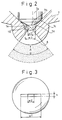
- Fig. 2 is an enlarged sectional view illustrating the vicinity of an injection hole 8 of the fuel injector valve according to a first comparative example
- Fig. 3 is a view when Fig. 2 is viewed from the direction of arrow (A).
- reference numeral 7a denotes a valve body
- 7b denotes a fuel reservoir communicated with the injection hole 8
- 7c denotes a nozzle seat portion that can be closed by the valve body 7a.
- the high pressure fuel is supplied to the fuel reservoir 7b via the nozzle seat portion 7c only when the valve body 7a is pulled up, whereby the fuel pressure in the fuel reservoir 7b is increased, and the fuel is injected from the injection hole 8.
- An opening on the outer side of the injection hole 8 at the downstream end in a direction in which the fuel is injected, is flat in cross-section and has the shape of a nearly rectangular slit with a width (w1) larger in the flattened direction than a height (h) thereof.
- the injection hole 8 has nearly a fan shape of which the width is gradually narrowed inward, i.e., gradually narrowed toward the upstream side in the direction in which the fuel is injected, so that the fuel can be injected at a predetermined angle ⁇ in the direction of width.
- the opening on the inner side at the upstream end in the direction in which the fuel is injected is flat in cross-section and is communicated with the fuel reservoir 7b via a nearly rectangular cross-section with a height (h) and a width (w2).
- the height of the injection hole 8 is nearly uniform in the direction of injection of a fan shape at the predetermined angle ⁇ in the direction of width.
- the side wall surface 7d of the fuel reservoir 7b is of a hemispherical shape having, as a center, the center of the predetermined angle ⁇ in the direction of width for injecting the fuel, i.e., a vertex 7e of a fan of the injection hole 8, whereby the fuel pressure in the fuel reservoir 7b equally acts on each portion of the injection hole 8 in the direction of injection.
- the bottom portion of the fuel reservoir 7b forms a circular flat bottom surface 7f with a diameter (w3) larger than the width (w2) of the opening on the inner side of the injection hole 8 at right angles with the center axis in the direction of injecting the fuel or, in other words, at right angles to a bisector of the included angle of the fan shape of the injection hole 8.
- the fuel reservoir 7b has nearly a spherical zone shape.
- the fuel injected from the injection hole 8 of the thus constituted fuel injector 7 forms a spray of a flat fan shape having a relatively small thickness corresponding to the height (h) of the injection hole 8, and almost all of the fuel comes into sufficient contact with the air taken into the cylinder and is favorably atomized. Furthermore, the bottom portion of the fuel reservoir 7b forms the flat bottom surface 7f having the diameter (w3) larger than the width (w2) of the opening on the inner side of the injection hole 8, and the opening on the inner side of the injection hole 8 is formed in the bottom surface 7f.
- the opening on the inner side of the injection hole 8 is necessarily formed in the flat bottom surface 7f of the fuel reservoir 7b not only when the center axis of the injection hole 8 corresponds to the center axis of the fuel reservoir 7b but also when the position for forming the injection hole 8 is deviated and the center axis of the injection hole 8 does not correspond to the center axis of the fuel reservoir 7b.
- the flat bottom surface 7f necessarily exists around the opening on the inner side of the injection hole 8, and the fuel (F) flows along the wall surface of the fuel reservoir 7b from the spherical side wall surface 7d to the flat bottom surface 7f, and flows into the injection hole 8. Therefore, the flow-in angle into the injection hole 8 is uniformly limited by the flat bottom surface 7f of the fuel reservoir 7b at any portion, and becomes constant. Accordingly, even if the injection hole 8 is formed at a deviated position, the angle at which the fuel flows into the injection holes 8 remains unchanged, so that the fuel is uniformly distributed in the injection hole 8, making it possible to form a fuel spray in compliance with the shape of the injection hole.
- the opening on the inner side of the injection hole 8 is necessarily formed in the flat bottom surface 7f of the fuel reservoir 7b. Therefore, even if an error occurs at the position for forming the injection hole 8, the opening on the inner side of the injection hole 8 has a constant sectional area, and the fuel is injected in a desired flow rate.
- the spray of a predetermined amount of fuel which is sufficiently atomized and has a small dispersion in the concentration can be supplied into the combustion chamber 5a on the top surface of the piston 5 in a compression stroke to accomplish a stratified combustion. Therefore, the stratified combustion takes place more stably. Since the fuel spray has a small thickness, a relatively large amount of fuel can be introduced into the combustion chamber, and the region of stratified combustion can be expanded toward the high-load side.
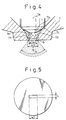
- Fig. 4 is an enlarged sectional view illustrating the vicinity of the injection hole,in the fuel injector according to a second comparative example and Fig. 5 is a view when Fig. 4 is viewed from the direction of arrow B.
- the valve body 7a, the fuel reservoir 7b, and the nozzle sheet portion 7c are basically the same as those of the fuel injector of the first comparative example, and will not be described again.
- the injection hole 9 is flat in cross section. It has an uniform height (h) and the width (w1) of the opening on the outer side which is equal to the width (w2) of the opening on the inner side and thus has a constant cross section of nearly a rectangular slit shape in the direction in which the fuel is injected, and has a very small length in the direction in which the fuel is injected.
- the opening on the inner side of the injection hole 9 at the upstream end in the direction in which the fuel is injected, is communicated with the fuel reservoir 7b at a nearly rectangular sectional shape with a height (h) and a width (w2).
- the side wall surface 7d of the fuel reservoir 7b is of a hemispherical shape whereby the fuel pressure in the fuel reservoir 7b equally acts on each portion of the injection hole 9 in the direction of injection.
- the bottom portion of the fuel reservoir 7b forms a circular flat bottom surface 7f with a diameter (w3) larger than the width (w2) of the opening on the inner side of the injection hole 9 at right angles with the center axis in the direction in which the fuel is injected.
- the injection hole has a small length in the direction in which the fuel is injected.
- the fuel is injected in a fan shape at an angle ⁇ defined by the width (w1) of the opening on the outer side of the injection hole 9 with the center of the hemispherical side surface 7d of the fuel reservoir 7b as a vertex 7e.
- the fuel injected from the injection hole 9 of the thus constituted fuel injection valve 7 forms a spray of a flat fan shape having a relatively small thickness corresponding to the height (h) of the injection hole 9, and almost all of the fuel comes into sufficient contact with the air taken into the cylinder and is favorably atomized. Furthermore, the bottom portion of the fuel reservoir 7b forms the flat bottom surface 7f having a diameter (w3) larger than the width (w2) of the opening on the inner side of the injection hole 9, and the opening on the inner side of the injection hole 9 is formed in the bottom surface 7f.
- the opening on the inner side of the injection hole 9 is necessarily formed in the flat bottom surface 7f of the fuel reservoir 7b not only when the center axis of the injection hole 9 corresponds to the center axis of the fuel reservoir 7b but also when the position for forming the injection hole 9 is deviated and the center axis of the injection hole 9 does not correspond to the center axis of the fuel reservoir 7b.
- the flat bottom surface 7f necessarily exists around the opening on the inner side of the injection hole 9, and the fuel F flows along the wall surface of the fuel reservoir 7b from the spherical side wall surface 7d to the flat bottom surface 7f, and flows into the injection hole 9. Therefore, the flow-in angle into the injection hole 9 is uniformly limited by the flat bottom surface 7f of the fuel reservoir 7b at any portion, and becomes constant. Accordingly, even when the injection hole 9 is formed at a deviated position, the angle at which the fuel flows into the injection holes 9 remains unchanged so that the fuel is uniformly distributed in the injection hole 9, making it possible to form a fuel spray of a predetermined shape.
- the opening on the inner side of the injection hole 9 is necessarily formed in the flat bottom surface 7f of the fuel reservoir 7b. Therefore, even if an error occurs at the position for forming the injection hole 9, the opening on the inner side of the injection hole 9 has a constant sectional area, and the fuel is injected in a desired flow rate.
- the injection hole 9 has a uniform sectional shape of a constant area. Accordingly, the injection hole 9 can be easily formed.
- the spray of a predetermined amount of fuel which is sufficiently atomized and has a small dispersion in the concentration, can be supplied into the combustion chamber 5a on the top surface of the piston 5 in a compression stroke to accomplish a stratified combustion. Therefore, the stratified combustion takes place more stably. Since the fuel spray has a small thickness, a rate of fuel that can be introduced into the combustion chamber increases. That is, a relatively large amount of fuel can be introduced into the combustion chamber, and the region of stratified combustion can be expanded toward the high-load side.
- Fig. 6 is an enlarged sectional view illustrating the vicinity of the injection hole in the fuel injector according to a third comparative example
- Fig. 7 is a view when Fig. 6 is viewed from the direction of arrow C.
- the valve body 7a, the fuel reservoir 7b, and the nozzle sheet portion 7c are basically the same as those of the fuel injector of the above-mentioned each comparative example, and will not be described again.
- the injection hole 9 is flat in cross section, and has an uniform height (h) and the width (w1) of the opening on the outer side which is equal to the width (w2) of the opening on the inner side and thus has a constant cross section of nearly a rectangular slit shape in the direction in which the fuel is injected, and has a very small length in the direction in which the fuel is injected.
- the injection hole 9 is not formed in the body of the fuel injector 7 but is formed in a tip member 10 having a flat surface which is a plate member separate from the body of the fuel injector 7. The tip member 10 in which the injection hole 9 is formed is secured by welding to a tip portion of the fuel injector 7.
- the opening on the inner side of the injection hole 9 at the upstream end, in the direction in which the fuel is injected, is communicated with the fuel reservoir 7b at a nearly rectangular sectional shape with a height (h) and a width (w2).
- the side wall surface 7d of the fuel reservoir 7b is of a hemispherical shape whereby the fuel pressure in the fuel reservoir 7b equally acts on each portion of the injection hole 9 in the direction of injection. According to this comparative example, therefore, space in the fuel reservoir 7b is defined by the side wall surface 7d of the fuel reservoir 7b and by the flat bottom surface 7f of the tip member 10.
- the bottom portion of the fuel reservoir 7b forms a circular flat bottom surface 7f with a diameter (w3) larger than the width (w2) of the opening on the inner side of the injection hole 9 at right angles with the center axis in the direction in which the fuel is injected. That is, in this embodiment, the hemispherical injection hole 7b is formed in the tip portion of the body of the fuel injector 7, and the bottom portion thereof is opened at a circular cross section having the diameter (w3).
- the injection hole 9 having the width (w2) of the opening of the inner side is formed in the tip portion, and the tip member 10 having a flat surface is combined therewith to thereby constitute the whole shape of the fuel reservoir 7b.
- the fuel is injected in a fan shape at an angle ⁇ defined by the width (w1) of the opening on the outer side of the injection hole 9 with the center of the hemispherical side surface 7d of the fuel reservoir 7b as a vertex 7e, since the injection hole has the small length in the direction in which the fuel is injected.
- the fuel injected from the injection hole 9 of the thus constituted fuel injector 7 forms a spray of a flat fan shape having a relatively small thickness corresponding to the height (h) of the injection hole 9, and almost all of the fuel comes into sufficient contact with the air taken into the cylinder and is favorably atomized. Furthermore, the bottom portion of the fuel reservoir 7b forms the flat bottom surface 7f having a diameter (w3) larger than the width (w2) of the opening on the inner side of the injection hole 9, and the opening on the inner side of the injection hole 9 is formed in the bottom surface 7f.
- the opening on the inner side of the injection hole 9 is necessarily formed in the flat bottom surface 7f of the fuel reservoir 7b not only when the center axis of the injection hole 9 corresponds to the center axis of the fuel reservoir 7b but also when the position for forming the injection hole 9 is deviated and the center axis of the injection hole 9 does not correspond to the center axis of the fuel reservoir 7b.
- the flat bottom surface 7f necessarily exists around the opening on the inner side of the injection hole 9, and the fuel F flows along the wall surface of the fuel reservoir 7b from the spherical side wall surface 7d to the flat bottom surface 7f, and flows into the injection hole 9. Therefore, the flow-in angle into the injection hole 9 is uniformly limited by the flat bottom surface 7f of the fuel reservoir 7b at any portion, and becomes constant. Accordingly, even when the injection hole 9 is formed at a deviated position, the angle at which the fuel flows into the injection hole 9 remains unchanged so that the fuel is uniformly distributed in the injection hole 9, making it possible to form a fuel spray of a predetermined shape.
- the opening on the inner side of the injection hole 9 is necessarily formed in the flat bottom surface 7f of the fuel reservoir 7b. Therefore, even if an error occurs at the position for forming the injection hole 9, the opening on the inner side of the injection hole 9 has a constant sectional area, and the fuel is injected at a desired flow rate. Besides, since the injection hole 9 has a uniform sectional shape of a constant area, the injection hole 9 can be easily formed.
- the fuel reservoir 7b defined by the hemispherical side wall surface 7d and by the flat bottom surface 7f, is constituted in combination with the body of the fuel injector 7 and the tip member 10 in which the injection hole 9 is formed. Therefore, the hemispherical fuel reservoir 7b may merely be formed in the body of the fuel injector 7, facilitating the production. This contributes to improving the dimensional precision of the fuel reservoir 7b as a whole.
- the spray of a predetermined amount of fuel which is sufficiently atomized and has a small dispersion in the concentration can be supplied into the combustion chamber 5a on the top surface of the piston 5 in a compression stroke to accomplish a stratified combustion. Therefore, the stratified combustion takes place more stably. Since the fuel spray has a small thickness, a rate of fuel that can be introduced into the combustion chamber increases. That is, a relatively large amount of fuel can be introduced into the combustion chamber, and the region of stratified combustion can be expanded toward the high-load side.
- Fig. 8 is an enlarged sectional view illustrating the vicinity of the injection hole in the fuel injector according to a first embodiment of the present invention
- Fig. 9 is a view when Fig. 8 is viewed from the direction of arrow D.
- the valve body 7a and the nozzle sheet portion 7c are basically the same as those of, the fuel injector of the above-mentioned each comparative example, and will not be described again.
- the injection hole 9 is flat in cross section, and has a constant cross section of nearly rectangular slit shape with a width of (w1) relative to the height (h).
- the injection hole has a very small length in the direction in which the fuel is injected.
- the injection hole 9 is not formed in the body of the fuel injector 7 but is formed in the tip member 10 which is a plate member separate from the body of the fuel injector 7.
- the hemispherical side wall surface 7d forming the fuel reservoir 7b is also formed in the tip member 10, and the injection hole 9 is communicated with the fuel reservoir 7b. That is, the injection hole 9 and the fuel reservoir 7b are integrally formed in the tip member 10 separate from the body of the fuel injector 7, and the tip member 10 is secured by welding to a tip portion of the fuel injector 7.
- the side wall surface 7d of the fuel reservoir 7b is of a hemispherical shape whereby the fuel pressure in the fuel reservoir 7b equally acts on each portion of the injection hole 9 in the direction of injection.
- the fuel is injected in a fan shape at an angle ⁇ defined by the width (w1) of the opening on the outer side of the injection hole 9 with the center of the hemispherical side surface 7d of the fuel reservoir 7b as a vertex 7e, since the injection hole has the small length in the direction in which the fuel is injected.
- the fuel injected from the injection hole 9 of the thus constituted fuel injector 7 forms a spray of a flat fan shape having a relatively small thickness corresponding to the height (h) of the injection hole 9, and almost all of the fuel comes into sufficient contact with the air taken into the cylinder and is favorably atomized.
- the fuel reservoir 7b and the injection hole 9 are integrally formed in the common tip member 10, the fuel reservoir 7b can be formed by pressing of a plate member, and the tip member 10 can be formed by press-punching of a portion of the injection hole 9.
- the center axis of the fuel reservoir 7b necessarily comes to correspond to the center axis of the injection hole 9 and thus they are not deviated from each other.
- the fuel F flows uniformly along the wall surface of the fuel reservoir 7b from the spherical side wall surface 7d into the injection hole 9. Therefore, the flow-in angle of the fuel into the injection hole 9 is uniform at any portion, and the fuel is uniformly distributed in the injection hole 9, making it possible to form a fuel spray of a predetermined shape.
- the tip member 10 in which are formed the injection hole 9 and the fuel reservoir 7b as defined by the hemispherical side wall surface 7d is secured to the tip portion of the fuel injector 7, and the center axis of the fuel reservoir 7b corresponds to the center axis of the injection hole 9 at the time of forming the tip member. Therefore, even if an error occurs at the time of mounting the tip member 10 on the tip portion of the fuel injector 7, a deviation in position between the tip member 10 and the body of the fuel injector 7 does not substantially affect the formation of the spray. Therefore, the fuel injector can be easily produced. Besides, since the injection hole 9 has a uniform sectional shape of a constant area, the injection hole 9 can be easily formed.
- the spray of a predetermined amount of fuel which is sufficiently atomized and has a small dispersion in the concentration can be supplied into the combustion chamber 5a on the top surface of the piston 5 in a compression stroke to accomplish a stratified combustion. Therefore, the stratified combustion takes place more stably. Since the fuel spray has a small thickness, the rate at which fuel can be introduced into the combustion chamber increases. That is, a relatively large amount of fuel can be introduced into the combustion chamber, and the region of stratified combustion can be expanded toward the high-load side.
- Fig. 10 is an enlarged sectional view illustrating the vicinity of the injection hole in the fuel injector according to a second embodiment of the present invention
- Fig. 11 is a view when Fig. 10 is viewed from the direction of arrow E.
- the valve body 7a and the nozzle sheet portion 7c are basically the same as those of the fuel injector of the above-mentioned embodiment, and will not be described again.
- An opening on the outer side of the injection hole 8 at the downstream end, in a direction in which the fuel is injected, is flat cross section and has the shape of a nearly rectangular slit with a width (w1) larger in the flattened direction than a height (h) thereof.
- the injection hole 8 has nearly a fan shape of which the width being gradually narrowed inward, i.e., gradually narrowed toward the upstream side, in the direction in which the fuel is injected, so that the fuel can be injected at a predetermined angle ⁇ in the direction of width.
- the opening on the inner side at the upstream end in the direction in which the fuel is injected, is flat in cross section and is communicated with the fuel reservoir 7b at a nearly rectangular cross section having a height (h) and a width (w2).
- the height of the injection hole 8 is nearly uniform in each direction of injection of a fan shape at the predetermined angle ⁇ in the direction of width.
- the side wall surface 7d of the fuel reservoir 7b is of a hemispherical shape having, as a center, the center of the predetermined angle ⁇ in the direction of width for injecting the fuel, i.e., a vertex 7e of a fan of the injection hole 8, whereby the fuel pressure in the fuel reservoir 7b equally acts on each portion of the injection hole 8 in the direction of injection.
- the injection hole 8 is not formed in the body of the fuel injector 7 but is formed in the tip member 10 which is a plate member separate from the body of the fuel injector 7.
- the hemispherical side wall surface 7d forming the fuel reservoir 7b is formed in the tip member 10. That is, the injection hole 8 and the fuel reservoir 7b are integrally formed in the tip member 10 separate from the body of the fuel injector 7, and the tip member 10 is secured by welding to a tip portion of the fuel injector 7.
- the fuel injected from the injection hole 8 of the thus constituted fuel injector 7 forms a spray of a flat fan shape having a relatively small thickness corresponding to the height (h) of the injection hole 8, and almost all of the fuel comes into sufficient contact with the air taken into the cylinder and is favorably atomized.
- the fuel reservoir 7b and the injection hole 8 are integrally formed in the common tip member 10, a part of the injection hole 8 which is uniform in cross section can be punched by pressing of the plate member. Then, the plate member is press-worked to form the fuel reservoir 7b, and the injection hole 8 is cut in a fan shape in the tip member 10.
- the center axis of the fuel reservoir 7b necessarily comes to correspond to the center axis of the injection hole 8 and thus, they are not deviated from each other. Accordingly, the fuel F flows uniformly along the wall surface of the fuel reservoir 7b from the spherical side wall surface 7d into the injection hole 8. Therefore, the flow-in angle of the fuel into the injection hole 8 is uniform at any portion, and the fuel is uniformly distributed in the injection hole 8, making it possible to form a fuel spray of a predetermined shape.
- the tip member 10 in which are formed the injection hole 8 and the fuel reservoir 7b defined by the hemispherical side wall surface 7d is secured to the tip portion of the fuel injector 7, and the position of the fuel reservoir 7b corresponds to the center axis of the injection hole 8 at the time of forming the tip member. Therefore, even if an error occurs at the time of mounting the tip member 10 on the tip portion of the fuel injector 7, a deviation in position between the tip member 10 and the body of the fuel injector 7 does not substantially affect the formation of the spray. Therefore, the fuel injection valve can be easily produced. Besides, since the injection hole 8 has a fan shape, the fuel smoothly flows along the side of the injection hole 8, and the flat fan shape of the fuel spray that is injected is more stabilized.
- the spray of a predetermined amount of fuel which is sufficiently atomized and has a small dispersion in the concentration can be supplied into the combustion chamber 5a on the top surface of the piston 5 in a compression stroke to accomplish a stratified combustion. Therefore, the stratified combustion takes place more stably. Since the fuel spray has a small thickness, the rate at which fuel can be introduced into the combustion chamber increases. That is, a relatively large amount of fuel can be introduced into the combustion chamber, and the region of stratified combustion can be expanded toward the high-load side.
- Fig. 12 is an enlarged sectional view illustrating the vicinity of the injection hole in the fuel injector according to a third embodiment of the present invention
- Fig. 13 is a view when Fig. 12 is viewed from the direction of arrow G.
- the valve body 7a and the nozzle sheet portion 7c are basically the same as those of the fuel injector of the above-mentioned each embodiment, and will not be described again.
- An opening on the outer side of the injection hole 8 at the downstream end, in a direction in which the fuel. is injected, is flat cross section and has the shape of a nearly rectangular slit with a width (w1) larger in the flattened direction than a height (h) thereof.
- the injection hole 8 has nearly a fan shape of which the width being gradually narrowed inward, i.e., gradually narrowed toward the upstream side in the direction in which the fuel is injected, so that the fuel can be injected at a predetermined angle ⁇ in the direction of width.
- the opening on the inner side at the upstream end in the direction in which the fuel is injected is flat cross section and has a nearly rectangular cross section with a height (h) and a width (w2).
- the height of the injection hole 8 is nearly uniform in each direction of injection of a fan shape at the predetermined angle ⁇ in the direction of width.
- the side wall surface 7d of the fuel reservoir 7b is of a hemispherical shape having, as a center, the center of the predetermined angle ⁇ in the direction of width for injecting the fuel, i.e., a vertex 7e of a fan of the injection hole 8, whereby the fuel pressure in the fuel reservoir 7b equally acts on each portion of the injection hole 8 in the direction of injection.
- the injection hole 8 is communicated with the fuel reservoir 7b via the passage 8a.
- the injection hole 8 and the passage 8a are not formed in the body of the fuel injector 7 but are formed in the tip member 10 which is a plate member separate from the body of the fuel injector 7.
- the hemispherical side wall surface 7d forming the fuel reservoir 7b is formed in the tip member 10. That is, the injection hole 8, passage 8a and fuel reservoir 7b are integrally formed in the tip member 10 separate from the body of the fuel injector 7, and the tip member 10 is secured by welding to a tip portion of the fuel injector 7.
- the fuel injected from the injection hole 8 of the thus constituted fuel injector 7 forms a spray of a flat fan shape having a relatively small thickness corresponding to the height (h) of the injection hole 8, and almost all of the fuel comes into sufficient contact with the air taken into the cylinder and is favorably atomized.
- the fuel reservoir 7b, passage 8a and injection hole 8 are integrally formed in the common tip member 10, the fuel reservoir 7b is formed by pressing the plate member, the passage 8a which has a uniform cross section is punched by press-work, and the injection hole 8 is cut in a fan shape thereby to form the tip member 10.
- the center axis of the fuel reservoir 7b necessarily comes to correspond to the center axis of the injection hole 8 and thus they are not deviated from each other.
- the fuel F flows uniformly along the wall surface of the fuel reservoir 7b from the spherical side wall surface 7d into the injection hole 8. Therefore, the flow-in angle of the fuel into the injection hole 8 is uniform at any portion, and the fuel is uniformly distributed in the injection hole 8, making it possible to form a fuel spray of a predetermined shape.
- the passage 8a having a constant sectional area is formed between the injection hole 8 and the fuel reservoir 7b. Accordingly, the amount of the fuel flowing into the injection hole 8 is limited by the passage 8a. Even if an error occurs in forming the injection hole 8 in the tip member 10, therefore, the fuel can be injected in a desired flow rate.
- the tip member 10 in which are formed the injection hole 8 and the fuel reservoir 7b defined by the hemispherical side wall surface 7d is secured to the tip portion of the fuel injector 7, and the center axis of the fuel reservoir 7b corresponds to the center axis of the injection hole 8 at the time of forming the tip member.
- the fuel injection valve can be easily produced. Besides, since the injection hole 8 has a fan shape, the fuel smoothly flows along the side of the injection hole 8, and the flat fan shape of the fuel spray that is injected is more stabilized.
- the spray of a predetermined amount of fuel which is sufficiently atomized and has a small dispersion in the concentration can be supplied into the combustion chamber 5a on the top surface of the piston 5 in a compression stroke to accomplish a stratified combustion. Therefore, the stratified combustion takes place more stably. Since the fuel spray has a small thickness, the rate at which fuel can be introduced into the combustion chamber increases. That is, a relatively large amount of fuel can be introduced into the combustion chamber, and the region of stratified combustion can be expanded toward the high-load side.
- the fuel reservoir is formed in a semispherical shape.
- the fuel reservoir is not limited in the semispherical shape.
- the fuel reservoir for example, may be a suitable shape such as tilted surfaces symmetrical with respect to the center axis thereof.
Landscapes
- Engineering & Computer Science (AREA)
- Chemical & Material Sciences (AREA)
- Combustion & Propulsion (AREA)
- Mechanical Engineering (AREA)
- General Engineering & Computer Science (AREA)
- Fuel-Injection Apparatus (AREA)
Claims (3)
- Ein Kraftstoffeinspritzventil für eine Brennkraftmaschine mit einem Ventilkörper (7a), einer Einspritzöffnung (8) mit einer Breite (w1) größer als ihre Höhe (hl) und einem Kraftstoffreservoir (7b), das in Strömungsrichtung hinter einem Ventilsitzbereich (7c) des Ventilkörpers (7a) angebracht ist, wobei dieses Kraftstoffreservoir (7b) mit dieser Einspritzöffnung (8) verbunden ist, ein Teil der Innenfläche dieses Kraftstoffreservoirs (7b) eine in Richtung der Breite (w1) gerichtete Geschwindigkeitskomponente in der Einspritzöffnung (8) dem Kraftstofffluss entlang dieses Teils der Innenfläche verleiht, ein anderer Teil dieser Innenfläche eine in Richtung der Breite gerichtete Geschwindigkeitskomponente in dieser Einspritzöffnung dem Kraftstofffluss entlang dieses anderen Teils dieser Innenfläche verleiht;
dadurch gekennzeichnet, dass
ein Spitzenelement (10) am Körper dieses Kraftstoffeinspritzventils angebracht ist, wobei mindestens ein Teil dieses Kraftstoffreservoirs (7b), das diesen einen und diesen anderen Teil dieser Innenfläche dieses Kraftstoffreservoirs (7b) umfasst, auf dem Spitzenelement (10) durch Pressen geformt wird und diese Einspritzöffnung (8) gleichzeitig in dieses Spitzenelement (10) durch dieses Pressen gestanzt wird. - Ein Kraftstoffeinspritzventil nach Anspruch 1; bei dem diese Einspritzöffnung (8) mit einem vorbestimmten gebildeten Winkel graduell nach innen verengt ist.
- Ein Kraftstoffeinspritzventil nach Anspruch 1 oder Anspruch 2; bei dem ein Durchlass mit einer konstanten Querschnittsfläche zwischen dieser Einspritzöffnung (8) und diesem Kraftstoffreservoir (7b) gebildet wird.
Applications Claiming Priority (2)
| Application Number | Priority Date | Filing Date | Title |
|---|---|---|---|
| JP10079968A JP3039510B2 (ja) | 1998-03-26 | 1998-03-26 | 内燃機関用燃料噴射弁 |
| JP7996898 | 1998-03-26 |
Publications (2)
| Publication Number | Publication Date |
|---|---|
| EP0945612A1 EP0945612A1 (de) | 1999-09-29 |
| EP0945612B1 true EP0945612B1 (de) | 2003-09-03 |
Family
ID=13705129
Family Applications (1)
| Application Number | Title | Priority Date | Filing Date |
|---|---|---|---|
| EP98121774A Expired - Lifetime EP0945612B1 (de) | 1998-03-26 | 1998-11-16 | Kraftstoffeinspritzventil für eine Brennkraftmaschine |
Country Status (5)
| Country | Link |
|---|---|
| US (1) | US6161781A (de) |
| EP (1) | EP0945612B1 (de) |
| JP (1) | JP3039510B2 (de) |
| KR (1) | KR100315273B1 (de) |
| DE (1) | DE69817759T2 (de) |
Families Citing this family (17)
| Publication number | Priority date | Publication date | Assignee | Title |
|---|---|---|---|---|
| DE19854828A1 (de) * | 1998-11-27 | 2000-05-31 | Bosch Gmbh Robert | Kraftstoffeinspritzdüse für selbstzündende Brennkraftmaschinen |
| DE60027288T2 (de) * | 1999-04-27 | 2006-08-31 | Siemens Vdo Automotive Corp., Auburn Hills | Brennstoffeinspritzventilsitz mit einer scharfen kante |
| JP3651338B2 (ja) * | 1999-12-15 | 2005-05-25 | 株式会社日立製作所 | 筒内燃料噴射弁およびこれを搭載した内燃機関 |
| DE10109611A1 (de) * | 2001-02-28 | 2002-09-05 | Bosch Gmbh Robert | Brennstoffeinspritzventil |
| US6752685B2 (en) | 2001-04-11 | 2004-06-22 | Lai East Laser Applications, Inc. | Adaptive nozzle system for high-energy abrasive stream cutting |
| DE10204656A1 (de) * | 2002-02-05 | 2003-09-25 | Bosch Gmbh Robert | Brennstoffeinspritzventil |
| DK200201605A (da) * | 2002-10-22 | 2004-04-23 | Hans Jensen Lubricators As | Ventil til montering i cyllindervæg |
| JP4103775B2 (ja) * | 2003-10-31 | 2008-06-18 | トヨタ自動車株式会社 | 筒内噴射式火花点火内燃機関 |
| US7040959B1 (en) * | 2004-01-20 | 2006-05-09 | Illumina, Inc. | Variable rate dispensing system for abrasive material and method thereof |
| US7793859B2 (en) * | 2006-04-11 | 2010-09-14 | Stone & Webster Process Technology, Inc. | Fluidized catalytic cracking feed nozzle |
| US20070284397A1 (en) * | 2006-06-09 | 2007-12-13 | Seaquist Closures Foreign, Inc,. | Valve-controlled dispensing closure |
| US20100139615A1 (en) * | 2007-02-13 | 2010-06-10 | Chandan Mahato | Direct injection flathead engine |
| US7572997B2 (en) * | 2007-02-28 | 2009-08-11 | Caterpillar Inc. | EDM process for manufacturing reverse tapered holes |
| JP2008232117A (ja) * | 2007-03-23 | 2008-10-02 | Toyota Central R&D Labs Inc | 燃料噴射弁 |
| JP4893709B2 (ja) * | 2008-08-08 | 2012-03-07 | トヨタ自動車株式会社 | 内燃機関の燃料噴射弁 |
| DE102012214522B3 (de) * | 2012-08-15 | 2014-03-27 | Ford Global Technologies, Llc | Einspritzventil |
| US10808668B2 (en) * | 2018-10-02 | 2020-10-20 | Ford Global Technologies, Llc | Methods and systems for a fuel injector |
Citations (1)
| Publication number | Priority date | Publication date | Assignee | Title |
|---|---|---|---|---|
| JPH09268961A (ja) * | 1996-03-30 | 1997-10-14 | Toyota Central Res & Dev Lab Inc | 筒内噴射用燃料噴射弁 |
Family Cites Families (15)
| Publication number | Priority date | Publication date | Assignee | Title |
|---|---|---|---|---|
| FR446892A (fr) * | 1912-08-03 | 1912-12-17 | Maschf Augsburg Nuernberg Ag | Dispositif pour l'admission du combustible dans les moteurs à combustion interne |
| DE682511C (de) * | 1936-10-13 | 1939-10-16 | Bosch Gmbh Robert | Spritzduese zum Zerstaeuben von Farbe und aehnlichen Fluessigkeiten |
| US4057190A (en) * | 1976-06-17 | 1977-11-08 | Bendix Corporation | Fuel break-up disc for injection valve |
| DE2658783C2 (de) * | 1976-12-24 | 1981-10-15 | M.A.N. Maschinenfabrik Augsburg-Nürnberg AG, 8500 Nürnberg | Luftverdichtende, direkt einspritzende Brennkraftmaschine |
| US4591099A (en) * | 1983-11-07 | 1986-05-27 | Spraying Systems Co. | Nozzle to provide fan-shaped spray pattern |
| JP2609929B2 (ja) * | 1989-08-21 | 1997-05-14 | 株式会社豊田中央研究所 | 燃料噴射弁 |
| JPH03225070A (ja) * | 1990-01-31 | 1991-10-04 | Isuzu Ceramics Kenkyusho:Kk | 燃料噴射ノズル及びその製造方法 |
| DE4104019C1 (de) * | 1991-02-09 | 1992-04-23 | Robert Bosch Gmbh, 7000 Stuttgart, De | |
| JPH0583368A (ja) * | 1991-09-20 | 1993-04-02 | Nec Corp | 局技術変更管理システム |
| JPH0763140A (ja) * | 1993-08-27 | 1995-03-07 | Toyota Motor Corp | 燃料噴射弁の噴射孔の形成方法 |
| JPH07151037A (ja) * | 1993-10-07 | 1995-06-13 | Toyota Central Res & Dev Lab Inc | 流体噴射ノズル |
| US5437413A (en) * | 1994-03-24 | 1995-08-01 | Siemens Automotive L.P. | Multiple disk air assist atomizer for fuel injection |
| US5484108A (en) * | 1994-03-31 | 1996-01-16 | Siemens Automotive L.P. | Fuel injector having novel multiple orifice disk members |
| JP3183156B2 (ja) * | 1995-04-27 | 2001-07-03 | 株式会社デンソー | 流体噴射ノズル |
| JP3156554B2 (ja) * | 1995-07-24 | 2001-04-16 | トヨタ自動車株式会社 | 燃料噴射弁 |
-
1998
- 1998-03-26 JP JP10079968A patent/JP3039510B2/ja not_active Expired - Fee Related
- 1998-11-02 US US09/184,050 patent/US6161781A/en not_active Expired - Lifetime
- 1998-11-16 EP EP98121774A patent/EP0945612B1/de not_active Expired - Lifetime
- 1998-11-16 DE DE69817759T patent/DE69817759T2/de not_active Expired - Lifetime
- 1998-11-30 KR KR1019980051673A patent/KR100315273B1/ko not_active Expired - Fee Related
Patent Citations (1)
| Publication number | Priority date | Publication date | Assignee | Title |
|---|---|---|---|---|
| JPH09268961A (ja) * | 1996-03-30 | 1997-10-14 | Toyota Central Res & Dev Lab Inc | 筒内噴射用燃料噴射弁 |
Non-Patent Citations (1)
| Title |
|---|
| JP-A-09268961 * |
Also Published As
| Publication number | Publication date |
|---|---|
| DE69817759D1 (de) | 2003-10-09 |
| JPH11280611A (ja) | 1999-10-15 |
| JP3039510B2 (ja) | 2000-05-08 |
| DE69817759T2 (de) | 2004-07-01 |
| EP0945612A1 (de) | 1999-09-29 |
| KR100315273B1 (ko) | 2002-07-12 |
| KR19990076549A (ko) | 1999-10-15 |
| US6161781A (en) | 2000-12-19 |
Similar Documents
| Publication | Publication Date | Title |
|---|---|---|
| CA2251677C (en) | Fuel injector for an internal combustion engine | |
| US6161781A (en) | Fuel injector for an internal combustion engine | |
| EP0918155B1 (de) | Brennstoffeinspritzventil | |
| US6708904B2 (en) | Nozzles suitable for use with fluid injectors | |
| US6105883A (en) | Fuel injector for an internal combustion engine | |
| EP0350885B1 (de) | Elektromagnetisches Kraftstoffeinspritzventil | |
| KR0130464B1 (ko) | 연료분사 밸브의 오리피스플레이트 | |
| US6070811A (en) | Fuel injector for an internal combustion engine | |
| US20090200403A1 (en) | Fuel injector | |
| US6142392A (en) | Fuel injector for an internal combustion engine | |
| US6155504A (en) | Fuel injector for an internal combustion engine | |
| JPH0378562A (ja) | 燃料噴射弁 | |
| US6935578B1 (en) | Fuel injection valve | |
| US6047904A (en) | Fuel injector for an internal combustion engine | |
| US20010042800A1 (en) | Electromagnetic fuel injection valve | |
| KR20000016842A (ko) | 연료분사밸브 | |
| US5666920A (en) | Fuel supply system for use with internal combustion engine | |
| JP3774822B2 (ja) | 可変スワール型燃料直噴インジェクタ | |
| JP3528656B2 (ja) | 内燃機関用燃料噴射弁 | |
| JP2001254658A (ja) | 燃料噴射弁 | |
| JP2855360B2 (ja) | 多方向噴射型インジェクタ | |
| JPH09209880A (ja) | 燃料噴射装置 | |
| JPH03164564A (ja) | 多方向噴射型インジェクタ | |
| JP2002357172A (ja) | 内燃機関用燃料噴射弁 |
Legal Events
| Date | Code | Title | Description |
|---|---|---|---|
| PUAI | Public reference made under article 153(3) epc to a published international application that has entered the european phase |
Free format text: ORIGINAL CODE: 0009012 |
|
| 17P | Request for examination filed |
Effective date: 19981116 |
|
| AK | Designated contracting states |
Kind code of ref document: A1 Designated state(s): DE FR GB |
|
| AX | Request for extension of the european patent |
Free format text: AL;LT;LV;MK;RO;SI |
|
| AKX | Designation fees paid |
Free format text: DE FR GB |
|
| 17Q | First examination report despatched |
Effective date: 20020212 |
|
| GRAH | Despatch of communication of intention to grant a patent |
Free format text: ORIGINAL CODE: EPIDOS IGRA |
|
| GRAS | Grant fee paid |
Free format text: ORIGINAL CODE: EPIDOSNIGR3 |
|
| GRAA | (expected) grant |
Free format text: ORIGINAL CODE: 0009210 |
|
| AK | Designated contracting states |
Kind code of ref document: B1 Designated state(s): DE FR GB |
|
| REG | Reference to a national code |
Ref country code: GB Ref legal event code: FG4D |
|
| REF | Corresponds to: |
Ref document number: 69817759 Country of ref document: DE Date of ref document: 20031009 Kind code of ref document: P |
|
| ET | Fr: translation filed | ||
| PLBE | No opposition filed within time limit |
Free format text: ORIGINAL CODE: 0009261 |
|
| STAA | Information on the status of an ep patent application or granted ep patent |
Free format text: STATUS: NO OPPOSITION FILED WITHIN TIME LIMIT |
|
| 26N | No opposition filed |
Effective date: 20040604 |
|
| PGFP | Annual fee paid to national office [announced via postgrant information from national office to epo] |
Ref country code: FR Payment date: 20051108 Year of fee payment: 8 |
|
| PGFP | Annual fee paid to national office [announced via postgrant information from national office to epo] |
Ref country code: GB Payment date: 20051116 Year of fee payment: 8 |
|
| GBPC | Gb: european patent ceased through non-payment of renewal fee |
Effective date: 20061116 |
|
| REG | Reference to a national code |
Ref country code: FR Ref legal event code: ST Effective date: 20070731 |
|
| PG25 | Lapsed in a contracting state [announced via postgrant information from national office to epo] |
Ref country code: GB Free format text: LAPSE BECAUSE OF NON-PAYMENT OF DUE FEES Effective date: 20061116 |
|
| PG25 | Lapsed in a contracting state [announced via postgrant information from national office to epo] |
Ref country code: FR Free format text: LAPSE BECAUSE OF NON-PAYMENT OF DUE FEES Effective date: 20061130 |
|
| PGFP | Annual fee paid to national office [announced via postgrant information from national office to epo] |
Ref country code: DE Payment date: 20121114 Year of fee payment: 15 |
|
| PG25 | Lapsed in a contracting state [announced via postgrant information from national office to epo] |
Ref country code: DE Free format text: LAPSE BECAUSE OF NON-PAYMENT OF DUE FEES Effective date: 20140603 |
|
| REG | Reference to a national code |
Ref country code: DE Ref legal event code: R119 Ref document number: 69817759 Country of ref document: DE Effective date: 20140603 |