EP0945640B1 - Isolateur de vibration - Google Patents
Isolateur de vibration Download PDFInfo
- Publication number
- EP0945640B1 EP0945640B1 EP99105548A EP99105548A EP0945640B1 EP 0945640 B1 EP0945640 B1 EP 0945640B1 EP 99105548 A EP99105548 A EP 99105548A EP 99105548 A EP99105548 A EP 99105548A EP 0945640 B1 EP0945640 B1 EP 0945640B1
- Authority
- EP
- European Patent Office
- Prior art keywords
- inner member
- tubular portion
- vibration isolator
- side stoppers
- elastic stopper
- Prior art date
- Legal status (The legal status is an assumption and is not a legal conclusion. Google has not performed a legal analysis and makes no representation as to the accuracy of the status listed.)
- Expired - Lifetime
Links
Images


Classifications
-
- F—MECHANICAL ENGINEERING; LIGHTING; HEATING; WEAPONS; BLASTING
- F16—ENGINEERING ELEMENTS AND UNITS; GENERAL MEASURES FOR PRODUCING AND MAINTAINING EFFECTIVE FUNCTIONING OF MACHINES OR INSTALLATIONS; THERMAL INSULATION IN GENERAL
- F16F—SPRINGS; SHOCK-ABSORBERS; MEANS FOR DAMPING VIBRATION
- F16F1/00—Springs
- F16F1/36—Springs made of rubber or other material having high internal friction, e.g. thermoplastic elastomers
- F16F1/38—Springs made of rubber or other material having high internal friction, e.g. thermoplastic elastomers with a sleeve of elastic material between a rigid outer sleeve and a rigid inner sleeve or pin, i.e. bushing-type
- F16F1/387—Springs made of rubber or other material having high internal friction, e.g. thermoplastic elastomers with a sleeve of elastic material between a rigid outer sleeve and a rigid inner sleeve or pin, i.e. bushing-type comprising means for modifying the rigidity in particular directions
-
- F—MECHANICAL ENGINEERING; LIGHTING; HEATING; WEAPONS; BLASTING
- F16—ENGINEERING ELEMENTS AND UNITS; GENERAL MEASURES FOR PRODUCING AND MAINTAINING EFFECTIVE FUNCTIONING OF MACHINES OR INSTALLATIONS; THERMAL INSULATION IN GENERAL
- F16F—SPRINGS; SHOCK-ABSORBERS; MEANS FOR DAMPING VIBRATION
- F16F1/00—Springs
- F16F1/36—Springs made of rubber or other material having high internal friction, e.g. thermoplastic elastomers
- F16F1/38—Springs made of rubber or other material having high internal friction, e.g. thermoplastic elastomers with a sleeve of elastic material between a rigid outer sleeve and a rigid inner sleeve or pin, i.e. bushing-type
Definitions
- the present invention relates to a vibration isolator used suitably as, for example, an engine mount which vibroisolatingly supports an engine unit to be mounted on a vehicle.
- This engine mount comprises a cylindrical inner member 5; a mounting member 6 having a tubular portion 61 which is disposed outside of and at a distance from the inner member 5 approximately coaxially with the inner member 5, and two mounting seat portions 62, 63 which are integrally formed at an outer periphery of the tubular portion 61; a rubber elastic body 7 disposed between and connecting integrally the inner member 5 and the tubular portion 61, and having axially through cavity portions 71, 72; and an elastic stopper 8 projecting from an inner circumferential surface of the tubular portion 61 in a manner to face the inner member 5 by way of one cavity portion 71.
- This engine mount is secured by fixing one of the inner member 5 and the mounting member 6 to an engine unit and fixing the other to a car body.
- the elastic stopper 8 is placed so as to stand in a main vibration input direction, and fore ends of brackets 55, 55 which are connected to both the ends of the inner member 5 are provided so as to face the side stoppers 65, 65.
- the rubber elastic body 7 disposed between the inner member 5 and the tubular portion 61 of the mounting member 6 is deformed elastically, thereby damping the vibrations effectively.
- the elastic stopper 8 is compressed by the inner member 5 and the tubular portion 61, whereby relative displacement of the inner member 5 and the mounting member 6 is restricted elastically and vibration transmitting power is reduced effectively.
- the above conventional engine mount uses the brackets 55, 55 which are connected to both the ends of the inner member 5, and the side stoppers 65, 65 which extend in the axially opposite directions from the tubular portion 61 of the mounting member 6, as a stopper structure for restricting excessive relative displacement of the inner member 5 and the mounting member 6 when strong vibrations are input.
- the tubular portion 61 of the mounting member 6 is increased in size. Besides, since the shape and size of the side stoppers 65, 65 must be determined in accordance with the shape and size of the brackets 55, 5 5 connected to the inner member 5, a lot of limitations are imposed on the design and the stopper structure becomes complicated.
- the present invention has been conceived to dissolve the above-mentioned inconveniences.
- a vibration isolator which dissolves the above inconveniences, comprises: an inner member; a mounting member having a tubular portion which is disposed outside of and at a distance from the inner member approximately coaxially with the inner member; a rubber elastic body disposed between and connecting integrally the inner member and the tubular portion, and having an axially through cavity portion; and an elastic stopper projecting from an inner circumferential surface of the tubular portion in a manner to face the inner member by way of the cavity portion, wherein the tubular portion has side stoppers which are disposed at both the axial ends of a portion where the elastic stopper is formed, in a manner to face the inner member, and which form therebetween a concave portion depressed in a radially outward direction; and the elastic stopper has a projection base portion which is embedded in the concave portion and which projects in a radially outward direction from fore end surfaces of the side stoppers.
- the vibration isolator can have a compact shape in which the tubular portion doesn't protrude axially.
- the elastic stopper for restricting elastically the relative displacement of the inner member and the mounting member is arranged in such a way that the projection base portion is embedded in the concave portion formed between both side stoppers. Owing to this projection base portion, the elastic stopper can attain a sufficiently large thickness (volume) and, as a result, the vibration transmitting power can be decreased effectively.
- the vibration isolator can attain both a reduction in the vibration transmitting power and superior durability of the elastic stopper, and can have a compact stopper structure.
- the side stoppers provided at the tubular portion of the mounting member are constituted by rigid bodies having an appropriate strength, and, for example, can be formed of metal, synthetic resin, or the like integrally with the tubular portion.
- a vibration isolator according to the second aspect of the present invention has a construction wherein, in the first aspect of the present invention, the mounting member is formed of synthetic resin.
- the mounting member including the tubular portion and the side stoppers is formed of a lightweight synthetic resin
- the mounting member can be sufficiently reduced in weight.
- a polyamide resin, for example, 6,6 -nylon can be suitably employed as a synthetic resin in view of strength.
- This synthetic resin may be improved in strength by being filled with such a reinforcing fiber as glass fiber.
- a vibration isolator according to the third aspect of the present invention has a construction wherein, in the second aspect of the present invention, the mounting member is formed by placing at least the elastic stopper in a molding die and carrying out injection molding, and the side stoppers are formed of synthetic resin integrally with the tubular portion.
- the elastic stopper is disposed between the side stoppers which are to be axially arranged in the molding die, the direction of removing the molding die can be set as an axial direction.
- the side stoppers can be integrally formed of synthetic resin without causing a problem with the direction of removing the molding die.
- a vibration isolator according to the fourth aspect of the present invention has a construction wherein, in any of the first to third aspects of the present invention, the elastic stopper has elastic skin layers extending axially and covering fore end surfaces of the side stoppers respectively.
- Figure 1 is a front view of a vibration isolator of the first preferred embodiment of the present invention.
- Figure 2 is a plan view of this vibration isolator.
- Figure 3 is a side view of this vibration isolator.
- Figure 4 is a cross sectional view taken along line IV-IV of Figure 1.
- Figure 5 is a cross sectional view taken along line V-V of Figure 3.
- the vibration isolator of this preferred embodiment mainly comprises, as shown in Figures 1 to 5, an inner member 1; a mounting member 2 formed of synthetic resin and having a tubular portion 21 which is disposed outside of and at a distance from the inner member 1 approximately coaxially with the inner member 1; a rubber elastic body 3 disposed between and connecting integrally the inner member 1 and the tubular portion 21, and having axially through cavity portions 31, 32; and an elastic stopper 4 projecting from an inner circumferential surface of the tubular portion 21 in a manner to face the inner member 1 by way of one cavity portion 31.
- the inner member 1 is made of such a metal as steel and has the shape of a pipe having a bore into which an attaching bolt or the like is inserted.
- the mounting member 2 comprises the tubular portion 21 having a pair of side stoppers 25, 25; and three mounting seat portions 22 to 24 projecting outward from an outer periphery of the tubular portion 2 1 and each having a mounting seat surface which lies in the same plane.
- the tubular portion 21 is formed approximately in the shape of a cylinder having a larger inner circumference than an outer circumference of the inner member 1 by a predetermined length and having a slightly smaller axial length than the inner member 1.
- a pair of side stoppers 25, 25 projecting from both the axial ends of the tubular portion 21 in a manner to face the inner member 1, and forming therebetween a concave portion 26 which is depressed in a radially outward direction.
- the height of the projections of these side stoppers 25, 25 is appropriately determined in consideration of the distance between the fore end surfaces of the side stoppers 25, 25 and the outer circumferential surface of the inner member 1.
- Nuts 22a to 24a which are to be screwed down on attaching bolts are respectively embedded in the mounting seat portions 22 to 24.
- This mounting member 2 is formed by injection molding 6,6 -nylon reinforced with 40 to 50 % by weight of glass fiber.
- the aforementioned inner member 1, and the rubber elastic body 3 and the elastic stopper 4 mentioned later are placed in a molding die, so that those are integrally connected to the mounting member 2 in predetermined positions.
- the elastic stopper 4 is placed between axially arranged portions where the pair of side stoppers 25, 25 are to be formed, the direction of removing the molding die can be set as an axial direction.
- formation of the side stoppers 25, 25 does not cause a problem with the direction of removing the molding die.
- the rubber elastic body 3 is formed by placing the inner member 1 in a vulcanization molding die and vulcanization molding a rubber material. So, the rubber elastic body 3 adheres by vulcanization to the outer circumferential surface of the inner member 1 and is formed approximately in an annular shape. The outer circumferential surface of this rubber elastic body 3 is made to adhere to the inner circumferential surface of the tubular portion 21, when the mounting member 2 is formed by injection molding. Thus, the rubber elastic body 3 is disposed between and connects integrally the inner member 1 and the tubular portion 21. In the rubber elastic body 3 on both the sides of portions sandwiching the inner member 1 in the main vibration input direction, there are axially through cavity portions 31, 32 for determining an appropriate spring constant of the rubber elastic body 3. This rubber elastic body 3 is integrally provided with rubber buffer portions 33, 33 which adhere to both the end surfaces of the tubular portion 21 and buffer an impact which one end surface of the tubular portion 21 has against a mating member thereof.
- the elastic stopper 4 is integrally formed of the same rubber material as the rubber elastic body 3. A part of the elastic stopper 4 is embedded in a concave portion 26 which is formed between the pair of side stoppers 25, 25 of the tubular portion 21.
- This elastic stopper 4 comprises a projection base portion 41 which is embedded in the concave portion 26 of the tubular portion 21 and projects in a radially outward direction from fore end surfaces of the side stoppers 25, 25; a projection head portion 42 protruding from the projection base portion 41 in a manner to face the inner member 1 by way of the cavity portion 31; and elastic skin layers 43, 43 extending in axially opposite directions from the projection head portion 42 and covering respectively the fore end surfaces of the side stoppers 25, 25. Since this elastic stopper 4 projects from the side of the tubular portion 21 in a manner to face the inner member 1, and both the circumferential ends of the projection base portion 41 are connected to the rubber elastic body 3, the cavity portion 31 is formed approximately in the shape of a reverse V.
- the vibration isolator of this preferred embodiment having the above-mentioned construction is used as an engine mount which vibroisolatingly supports an engine unit to be mounted on a vehicle.
- This vibration isolator is secured by fixing, for example, the inner member 1 to an engine unit with an attaching bolt and a nut or the like on one hand, and by fixing the mounting seat portions 22-24 of the mounting member 2 to a car body with attaching bolts, etc. on the other hand, so that the elastic stopper 4 is placed so as to stand in a main vibration input direction.
- the rubber elastic body 3 disposed between the inner member 1 and the tubular portion 21 of the mounting member 2 is deformed elastically, thereby damping the vibrations effectively.
- the elastic stopper 4 is compressed by the inner member 1 and the tubular portion 21, and relative displacement of the inner member 1 and the mounting member 2 is elastically restricted, whereby the vibration transmitting power is decreased effectively.
- the vibration isolator of this preferred embodiment can have a compact shape in which the tubular portion 21 doesn't protrude axially, since the side stoppers 25, 25 for restricting excessive relative displacement of the inner member 1 and the mounting member 2 are disposed at both the axial ends of a portion of the tubular portion 21 so as to project in a manner to face the inner member 1.
- the elastic stopper 4 for restricting elastically relative displacement of the inner member 1 and the mounting member 2 is arranged in such a way that the projection base portion 41 is embedded in the concave portion 26 which is formed by both the side stoppers 25, 25. Owing to this projection base portion 41, the elastic stopper 4 can attain a sufficiently large thickness (volume), and, as a result, vibration transmitting power can be reduced effectively.
- the vibration isolator of this preferred embodiment can attain both a reduction in the vibration transmitting power and superior durability of the elastic stopper 4, and can have a compact stopper structure.
- the mounting member 2 of this preferred embodiment can be reduced in weight sufficiently, because almost all parts thereof are formed of a lightweight synthetic resin.
- this mounting member 2 is formed by placing the elastic stopper 4 in a molding die and carrying out injection molding, the elastic stopper 4 is placed between the side stoppers 25, 25 which are to be axially arranged in the molding die, and the direction of removing the molding die is set as an axial direction. So, the side stoppers 25, 25 can be formed of synthetic resin integrally with the tubular portion 21 without causing a problem with the direction of removing the molding die.
- the elastic stopper 4 of this preferred embodiment has the elastic skin layers 43, 43 extending axially from the projection head portion 42 and covering the fore end surfaces of the side stoppers 25, 25 respectively, an impact which generates in restricting excessive relative displacement of the inner member 1 and the mounting member 2 can be buffered.
- Figure 6 is a front view of the vibration isolator of the second preferred embodiment of the present invention.
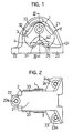
- Figure 7 is a plan view of this vibration isolator.
- Figure 8 is a side view of that vibration isolator.
- Figure 9 is a cross sectional view taken along line IX-IX of Figure 6.
- Figure 10 is a cross sectional view taken along line X-X of Figure 8.
- the vibration isolator of this preferred embodiment mainly comprises, as shown in Figures 6 to 10, an inner member 101 formed of such a metal as steel in the shape of a pipe; a mounting member 102 formed of synthetic resin and having a tubular portion 121 which is disposed outside of and at a distance from the inner member 101 approximately coaxially with the inner member 101; a rubber elastic body 103 disposed between and connecting integrally the inner member 101 and the tubular portion 121, and having axially through cavity portions 131, 132; and an elastic stopper 104 projecting from an inner circumferential surface of the tubular potion 121 in a manner to face the inner member 101 by way of one cavity portion 131.
- This vibration isolator has basically the same construction as that of the first preferred embodiment except the shapes of the concave portion 126 provided in the tubular portion 121 of the mounting member 102, the rubber elastic body 103 and the elastic stopper 104.
- the mounting member 102 comprises the tubular portion 121 having a pair of side stoppers 125, 125, and three mounting seat portions 122 to 124 projecting outward from an outer periphery of the tubular portion 121 and each having a mounting seat surface which lies in the same plane.
- a predetermined position the position in the main vibration input direction
- flat plane portions at both the axial ends of the concave portion 126 constitute one pair of side stoppers 125, 125 which respectively face the ends of the inner member 101. Since flat planes which are even with the side stoppers 125, 125 are also formed at both the circumferential sides of the concave portion 126, the circumferential length of each of the side stoppers 1 25, 125 is substantially larger than that of the first preferred embodiment.
- the respective mounting seat portions 122-124 are provided in adjustment with the position of a mating member to which these portions 122-124 are fixed, their position and shape is slightly different from that of the first preferred embodiment.
- nuts 122a-124a are respectively embedded in the same manner as in the first preferred embodiment.
- This mounting member 102 is formed by injection molding the same resin molding material as that of the first preferred embodiment in the same manner as in the first preferred embodiment. That is to say, by placing at least the elastic stopper 104 in a molding die and then molding the mounting member 102, the side stoppers 125, 125 are integrally formed of resin without causing a problem with the direction of removing the molding die.
- the rubber elastic body 103 is formed approximately in an annular shape in the same manner as the rubber elastic body 3 of the first preferred embodiment, and is disposed between and connects integrally the inner member 101 and the tubular portion 121.
- This rubber elastic body 103 integrally has belt-shaped rubber buffer portions 133, 133 which adhere to both the end surfaces of the tubular portion 121, but their arrangement is slightly different from that of the first preferred embodiment.
- the elastic stopper 104 is integrally formed of the same rubber material as the rubber elastic body 103 in the same manner as in the first preferred embodiment, and a part of the elastic stopper 104 is embedded in the concave portion 126 of the tubular portion 121.
- This elastic stopper 104 comprises a projection base portion 141 embedded in the concave portion 126 of the tubular portion 121 and projecting in a radially outward direction from the fore end surfaces of the side stoppers 125, 125; a projection head portion 142 projecting from the projection base portion 141 in a manner to face the inner member 101 by way of the cavity portion 131; and elastic skin layers 143, 143 extending in all the radial directions from the projection head portion 142 and covering the fore end surfaces of the side stoppers 125, 125, respectively.
- this elastic stopper 104 projects from the side of the tubular portion 121 in a manner to face the inner member 101, and both the circumferential ends of the elastic skin layers 143, 143 are connected to the rubber elastic body 103, the cavity portion 131 approximately has the shape of an arc.
- the projection base portion 141 of this elastic stopper 104 has a larger circumferential length and accordingly a larger volume than the projection base portion 41 of the first preferred embodiment, since the concave portion 126 has a larger circumferential length than the concave portion 26 of the first preferred embodiment.
- the vibration isolator of this preferred embodiment having the above construction is used as an engine mount which vibroisolatingly supports an engine unit to be mounted on a vehicle after being secured in the same way as that of the first preferred embodiment, and exhibits similar functions and effects to those of the first preferred embodiment. That is to say, the vibration isolator of this preferred embodiment achieves both a reduction in the vibration transmitting power and superior durability of the elastic stopper 104, and can have a compact stopper structure.
- the side stoppers 125, 125 of this preferred embodiment can function as stoppers even when vibrations are input in a direction slightly different from the main vibration input direction, since flat planes which are even with the side stoppers 125, 125 are formed at both the circumferential ends of the concave portion 126 and so the side stoppers 125, 125 have a larger circumferential length.
- the side stoppers 125, 125 of this preferred embodiment can exhibit a stopper function against vibrations input in a wider range of directions when compared to those of the first preferred embodiment.
- the elastic stopper 104 of this preferred embodiment is advantageous in reducing the vibration transmitting power more effectively, because the volume of the projection base portion 141 embedded in the concave portion 126 is larger than that of the projection base portion 41 of the first preferred embodiment.
Landscapes
- Engineering & Computer Science (AREA)
- General Engineering & Computer Science (AREA)
- Mechanical Engineering (AREA)
- Springs (AREA)
- Arrangement Or Mounting Of Propulsion Units For Vehicles (AREA)
- Vibration Prevention Devices (AREA)
Claims (4)
- Isolateur de vibrations comprenant :caractérisé en ce queun élément interne (1) ;un élément de montage (2) comportant une partie tubulaire (21) qui est disposée à l'extérieur et à une certaine distance dudit élément interne, de façon coaxiale avec ledit élément interne ;un corps élastique en caoutchouc (3) disposé entre ledit élément interne et ladite partie tubulaire et les reliant d'une seule pièce et comportant une partie de cavité axialement traversante (31) ; etune butée élastique(4) dépassant à partir d'une surface circonférentielle interne de ladite partie tubulaire (21) de manière à faire face audit élément interne (1) par l'intermédiaire de ladite partie de cavité (31),
ladite partie tubulaire (21) comporte des butées latérales(25) qui sont disposées aux deux extrémités axiales d'une partie où est formée ladite butée élastique(4), de manière à faire face audit élément interne (1) et qui forment entre elles une partie concave (26) en dépression dans un sens radialement vers l'extérieur et s'étendant entre lesdites butées latérales (25) et
ladite butée élastique(4) comporte une partie de base en saillie (41) qui est noyée dans ladite partie concave (26) et qui dépasse dans un sens radialement vers l'extérieur à partir des surfaces d'extrémités avant desdites butées latérales(25). - Isolateur de vibrations selon la revendication 1, dans lequel ledit élément de montage (2) est constitué de résine synthétique.
- Isolateur de vibrations selon la revendication 2, dans lequel on forme ledit élément de montage (2) en plaçant au moins ladite butée élastique(4) dans un moule et en exécutant le moulage par injection et on constitue lesdites butées latérales(25) en résine synthétique d'une seule pièce avec ladite partie tubulaire (21).
- Isolateur de vibrations selon l'une quelconque des revendications 1, 2 et3, dans lequel ladite butée élastique(4) comporte des couches de peau élastiques (43) s'étendant axialement et recouvrant les surfaces d'extrémités avant desdites butées latérales (25) respectivement.
Applications Claiming Priority (4)
| Application Number | Priority Date | Filing Date | Title |
|---|---|---|---|
| JP7423598 | 1998-03-23 | ||
| JP7423598 | 1998-03-23 | ||
| JP01252999A JP3509602B2 (ja) | 1998-03-23 | 1999-01-20 | 防振装置 |
| JP1252999 | 1999-01-20 |
Publications (3)
| Publication Number | Publication Date |
|---|---|
| EP0945640A2 EP0945640A2 (fr) | 1999-09-29 |
| EP0945640A3 EP0945640A3 (fr) | 2002-02-13 |
| EP0945640B1 true EP0945640B1 (fr) | 2004-06-02 |
Family
ID=26348153
Family Applications (1)
| Application Number | Title | Priority Date | Filing Date |
|---|---|---|---|
| EP99105548A Expired - Lifetime EP0945640B1 (fr) | 1998-03-23 | 1999-03-18 | Isolateur de vibration |
Country Status (4)
| Country | Link |
|---|---|
| US (1) | US6213455B1 (fr) |
| EP (1) | EP0945640B1 (fr) |
| JP (1) | JP3509602B2 (fr) |
| DE (1) | DE69917704T2 (fr) |
Families Citing this family (16)
| Publication number | Priority date | Publication date | Assignee | Title |
|---|---|---|---|---|
| JP3164101B2 (ja) * | 1999-05-18 | 2001-05-08 | 東海ゴム工業株式会社 | 防振装置 |
| DE10131105C1 (de) * | 2001-06-27 | 2003-01-02 | Freudenberg Carl Kg | Aggregatelager in Buchsenform |
| JP3687964B2 (ja) * | 2002-09-24 | 2005-08-24 | アイ・アンド・ピー株式会社 | 伝動装置用サンドイッチ成形可動ガイド |
| JP2004316798A (ja) * | 2003-04-17 | 2004-11-11 | Bridgestone Corp | 防振装置 |
| KR100788311B1 (ko) * | 2006-10-25 | 2007-12-27 | (주)디티알 | 차량의 파워트레인 마운트 |
| JP2012097878A (ja) * | 2010-11-05 | 2012-05-24 | Kurashiki Kako Co Ltd | 防振連結ロッド |
| JP2012122571A (ja) * | 2010-12-09 | 2012-06-28 | Toyo Tire & Rubber Co Ltd | 防振装置 |
| JP5562821B2 (ja) * | 2010-12-13 | 2014-07-30 | 倉敷化工株式会社 | 防振装置 |
| US20130134641A1 (en) * | 2011-11-29 | 2013-05-30 | Kurashiki Kako Co., Ltd. | Vibration isolator |
| CN103387013B (zh) * | 2012-11-12 | 2016-08-17 | 襄阳群龙汽车部件股份有限公司 | 一种汽车驾驶室前悬减振机构 |
| US9205733B2 (en) | 2013-02-06 | 2015-12-08 | Honda Motor Co., Ltd. | Vehicle including mount devices for coupling a sub-frame with a main frame |
| US8985260B2 (en) | 2013-02-06 | 2015-03-24 | Honda Motor Co., Ltd. | Vehicle including exhaust system attached to sub-frame |
| JP6002607B2 (ja) * | 2013-03-12 | 2016-10-05 | 住友理工株式会社 | 防振装置 |
| JP2017101738A (ja) * | 2015-12-01 | 2017-06-08 | 住友理工株式会社 | 筒形防振装置 |
| KR102479485B1 (ko) * | 2016-12-13 | 2022-12-19 | 현대자동차주식회사 | 분산된 스토퍼들을 가지는 자동차의 트랜스미션 마운트 |
| CN107804154B (zh) * | 2017-09-21 | 2023-09-29 | 安徽中鼎减震橡胶技术有限公司 | 尼龙支架橡胶主簧及其制造方法 |
Family Cites Families (10)
| Publication number | Priority date | Publication date | Assignee | Title |
|---|---|---|---|---|
| JPH0357531U (fr) * | 1989-10-12 | 1991-06-03 | ||
| JPH0454334A (ja) * | 1990-06-20 | 1992-02-21 | Bridgestone Corp | ブラケット一体型防振装置及びその製法 |
| JPH0442937U (fr) * | 1990-08-09 | 1992-04-13 | ||
| DE4137977C2 (de) * | 1991-11-19 | 1995-06-14 | Freudenberg Carl Fa | Mehrkammer-Hydrobuchse |
| US5551661A (en) * | 1994-10-11 | 1996-09-03 | Bunker; Donald D. | Automotive transmission mount |
| JPH08135723A (ja) * | 1994-11-10 | 1996-05-31 | Tokai Rubber Ind Ltd | 流体封入式筒型マウント |
| DE19618688C2 (de) * | 1996-05-09 | 1999-03-25 | Freudenberg Carl Fa | Hydrobuchse |
| EP0809039A1 (fr) * | 1996-05-24 | 1997-11-26 | Firma Carl Freudenberg | Ressort du type à manchon de caoutchouc |
| DE19622248C2 (de) * | 1996-06-04 | 1999-02-18 | Freudenberg Carl Fa | Hydraulisch dämpfende Hülsengummifeder |
| DE19640531C2 (de) * | 1996-10-01 | 2000-06-08 | Mannesmann Boge Gmbh | Hydraulisch dämpfendes Gummilager |
-
1999
- 1999-01-20 JP JP01252999A patent/JP3509602B2/ja not_active Expired - Fee Related
- 1999-03-17 US US09/268,724 patent/US6213455B1/en not_active Expired - Lifetime
- 1999-03-18 DE DE69917704T patent/DE69917704T2/de not_active Expired - Fee Related
- 1999-03-18 EP EP99105548A patent/EP0945640B1/fr not_active Expired - Lifetime
Also Published As
| Publication number | Publication date |
|---|---|
| US6213455B1 (en) | 2001-04-10 |
| DE69917704T2 (de) | 2005-06-09 |
| EP0945640A2 (fr) | 1999-09-29 |
| EP0945640A3 (fr) | 2002-02-13 |
| JP3509602B2 (ja) | 2004-03-22 |
| JPH11336817A (ja) | 1999-12-07 |
| DE69917704D1 (de) | 2004-07-08 |
Similar Documents
| Publication | Publication Date | Title |
|---|---|---|
| EP0945640B1 (fr) | Isolateur de vibration | |
| US4667764A (en) | Resilient mounting device for transversely disposed engine of front-engine front-drive vehicle | |
| JPH0932875A (ja) | 筒形防振支持体 | |
| JPH0510014U (ja) | 車両サスペンシヨン用バウンドストツパ | |
| JP3164101B2 (ja) | 防振装置 | |
| CN111102311B (zh) | 防振衬套 | |
| WO1999015809A1 (fr) | Montage antivibrations | |
| JPH08233030A (ja) | 連結ロッド | |
| JP2000193003A (ja) | 自動車用エンジンロールマウント | |
| JPH10274268A (ja) | 防振ブッシュおよびブッシュ組立体 | |
| JP2004028267A (ja) | 防振ブッシュ | |
| JP2001295887A (ja) | 防振装置 | |
| JP4442371B2 (ja) | トルクロッド | |
| CN118375680A (zh) | 合成橡胶衬套 | |
| JPH10299833A (ja) | エンジンマウント装置 | |
| JPH08159216A (ja) | 防振装置 | |
| JPH0725476Y2 (ja) | サスペンションメンバー用防振体 | |
| JPH0474569B2 (fr) | ||
| JP3852292B2 (ja) | 自動車用の防振ブッシュ構造 | |
| JPH07158675A (ja) | 防振装置 | |
| JP3456286B2 (ja) | 筒型防振マウント | |
| JPH06280914A (ja) | 筒状防振ブッシュ | |
| JPH08100831A (ja) | ストラットマウント | |
| JP2001317578A (ja) | 防振ブッシュ | |
| JP3700237B2 (ja) | 筒型マウントおよびその製造方法 |
Legal Events
| Date | Code | Title | Description |
|---|---|---|---|
| PUAI | Public reference made under article 153(3) epc to a published international application that has entered the european phase |
Free format text: ORIGINAL CODE: 0009012 |
|
| 17P | Request for examination filed |
Effective date: 19990318 |
|
| AK | Designated contracting states |
Kind code of ref document: A2 Designated state(s): AT BE CH CY DE DK ES FI FR GB GR IE IT LI LU MC NL PT SE Kind code of ref document: A2 Designated state(s): DE FR GB |
|
| AX | Request for extension of the european patent |
Free format text: AL;LT;LV;MK;RO;SI |
|
| PUAL | Search report despatched |
Free format text: ORIGINAL CODE: 0009013 |
|
| AK | Designated contracting states |
Kind code of ref document: A3 Designated state(s): AT BE CH CY DE DK ES FI FR GB GR IE IT LI LU MC NL PT SE |
|
| AX | Request for extension of the european patent |
Free format text: AL;LT;LV;MK;RO;SI |
|
| RIC1 | Information provided on ipc code assigned before grant |
Free format text: 7F 16F 1/38 A, 7F 16F 1/387 B |
|
| AKX | Designation fees paid |
Free format text: DE FR GB |
|
| GRAP | Despatch of communication of intention to grant a patent |
Free format text: ORIGINAL CODE: EPIDOSNIGR1 |
|
| GRAS | Grant fee paid |
Free format text: ORIGINAL CODE: EPIDOSNIGR3 |
|
| GRAA | (expected) grant |
Free format text: ORIGINAL CODE: 0009210 |
|
| AK | Designated contracting states |
Kind code of ref document: B1 Designated state(s): DE FR GB |
|
| REG | Reference to a national code |
Ref country code: GB Ref legal event code: FG4D |
|
| REF | Corresponds to: |
Ref document number: 69917704 Country of ref document: DE Date of ref document: 20040708 Kind code of ref document: P |
|
| REG | Reference to a national code |
Ref country code: IE Ref legal event code: FG4D |
|
| ET | Fr: translation filed | ||
| PGFP | Annual fee paid to national office [announced via postgrant information from national office to epo] |
Ref country code: FR Payment date: 20050308 Year of fee payment: 7 |
|
| PLBE | No opposition filed within time limit |
Free format text: ORIGINAL CODE: 0009261 |
|
| 26N | No opposition filed |
Effective date: 20050303 |
|
| REG | Reference to a national code |
Ref country code: FR Ref legal event code: ST Effective date: 20061130 |
|
| PGFP | Annual fee paid to national office [announced via postgrant information from national office to epo] |
Ref country code: GB Payment date: 20070314 Year of fee payment: 9 |
|
| PG25 | Lapsed in a contracting state [announced via postgrant information from national office to epo] |
Ref country code: FR Free format text: LAPSE BECAUSE OF NON-PAYMENT OF DUE FEES Effective date: 20060331 |
|
| PGFP | Annual fee paid to national office [announced via postgrant information from national office to epo] |
Ref country code: DE Payment date: 20080313 Year of fee payment: 10 |
|
| GBPC | Gb: european patent ceased through non-payment of renewal fee |
Effective date: 20080318 |
|
| PG25 | Lapsed in a contracting state [announced via postgrant information from national office to epo] |
Ref country code: GB Free format text: LAPSE BECAUSE OF NON-PAYMENT OF DUE FEES Effective date: 20080318 |
|
| PG25 | Lapsed in a contracting state [announced via postgrant information from national office to epo] |
Ref country code: DE Free format text: LAPSE BECAUSE OF NON-PAYMENT OF DUE FEES Effective date: 20091001 |