EP0945651A2 - Tendeur de chaíne mécanique - Google Patents
Tendeur de chaíne mécanique Download PDFInfo
- Publication number
- EP0945651A2 EP0945651A2 EP99114027A EP99114027A EP0945651A2 EP 0945651 A2 EP0945651 A2 EP 0945651A2 EP 99114027 A EP99114027 A EP 99114027A EP 99114027 A EP99114027 A EP 99114027A EP 0945651 A2 EP0945651 A2 EP 0945651A2
- Authority
- EP
- European Patent Office
- Prior art keywords
- chain tensioner
- transverse
- mechanical chain
- base body
- moulded
- Prior art date
- Legal status (The legal status is an assumption and is not a legal conclusion. Google has not performed a legal analysis and makes no representation as to the accuracy of the status listed.)
- Granted
Links
- 238000002485 combustion reaction Methods 0.000 abstract description 3
- 239000002184 metal Substances 0.000 abstract description 3
- 239000007787 solid Substances 0.000 abstract description 2
- 238000001746 injection moulding Methods 0.000 abstract 1
- 230000003014 reinforcing effect Effects 0.000 abstract 1
- 229920002994 synthetic fiber Polymers 0.000 abstract 1
- 230000005540 biological transmission Effects 0.000 description 1
- 230000002349 favourable effect Effects 0.000 description 1
- 230000037431 insertion Effects 0.000 description 1
- 238000003780 insertion Methods 0.000 description 1
- 238000004519 manufacturing process Methods 0.000 description 1
- 238000004381 surface treatment Methods 0.000 description 1
Images
Classifications
-
- F—MECHANICAL ENGINEERING; LIGHTING; HEATING; WEAPONS; BLASTING
- F16—ENGINEERING ELEMENTS AND UNITS; GENERAL MEASURES FOR PRODUCING AND MAINTAINING EFFECTIVE FUNCTIONING OF MACHINES OR INSTALLATIONS; THERMAL INSULATION IN GENERAL
- F16H—GEARING
- F16H7/00—Gearings for conveying rotary motion by endless flexible members
- F16H7/08—Means for varying tension of belts, ropes or chains
- F16H2007/0863—Finally actuated members, e.g. constructional details thereof
- F16H2007/0872—Sliding members
Definitions
- the invention relates to a mechanical chain tensioner in the preamble of Claim 1 specified Art.
- the Basic body is a stamped and bent part made of sheet metal with a constant wall thickness.
- the basic body has an arched vertical web, on its concave underside for reasons of rigidity a transverse wall is bent.
- Form two punched holes Fastening receptacles in which sleeves are riveted or pressed into the sleeves and be welded.
- An abutment for the tensioning bracket is a riveted into the web Bearing journal on which the clamping bracket is pushed in the longitudinal direction of the journal and is secured against being pulled off by an additional security element.
- the basic body is expensive and heavy to manufacture. He must for every fastening case be tailor-made, so to speak, as the spacing of the mounting brackets are different for different types of internal combustion engines. Furthermore the base body needs a surface treatment.
- a chain tensioner known from EP-A-0 581 219 is a solid, metallic one Carrier provided for the clamping bracket.
- the invention has for its object a mechanical chain tensioner to create the type mentioned above, which is universally applicable.
- the base body can be used optionally for at least two different applications, where the distances between the attachment points differ. To the Then the appropriate mounting hole is selected. So that leaves the basic body can be used universally.
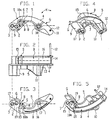
- a mechanical chain tensioner in particular for an internal combustion engine, has a base body G.
- a clamping bracket B can be attached to the base body G or attached, which is intended to work with a chain, not shown.
- the base body G has abutments.
- the Base body G is a one-piece molded part with molded in transverse projections 10.9 Mounting holes, 1,2,3; (to define the basic body G).
- the cross tabs 9, 10 protrude from a central web 4 and are formed in one piece with this. Run along the curved underside of the central web 4 on both sides transverse walls 5 on the side on which the transverse projections 9, 10 protrude, connect the transverse projections 9, 10 with each other stiffening.
- Additional Stiffening ribs 13 can be provided.
- Center web 4 has a through hole 11 for a securing element 12.
- An arcuate curved transverse wall 6 extends from the transverse projection 9 to the transverse wall 5, an approximately between the two transverse walls 5,6 triangular window 7 is limited, which passes through the central web 4.
- On the cross wall 5 is on the side of the central web 4 facing away from the transverse projections 9, 10 an approximate, e.g. triangular bracket 8 integrally formed, the wall thickness corresponds approximately to the wall thickness of the central web 4 and / or the transverse walls 5, 6.
- Coaxial bearing journals 18a, 18b are provided, which are approximately perpendicular to the central web 4 run and protrude from one side of the bearing block 8.
- the bearing block 8 forms with the journals 18a, 18b a pivot bearing S for the on the base body G to be mounted clamp B, which is expediently a molded part with resilient Properties is.
- the clamping bracket B is detachable with the base body G Locking connection R connected (Fig. 3 and 5) and is through the bearing block 8 in Centered axis direction of the journals 18a, 18b.
- the tensioning bracket B has an end 14 which is secured by means of the securing element 12 for assembling or disassembling the chain tensioner etc. can be fixed on the central web 4.
- the other end of the clamping bracket B is designed as a bearing eye 15 and on Swivel bearing S pivotally attached.
- the back of the curved clamp B defines a sliding surface 16.
- the bearing eye 15 is fork-shaped (Fig. 5), so that the bearing block 8 between Side walls 20 of the bearing eye 15 engages and causes centering.
- At least the transverse projection 9 contains at least two, preferably closely adjacent, Fastening holes 2,3, so that one and the same base body G optionally using the mounting hole 1 and the mounting hole 2 or can fix the mounting hole 3.
- the base body G is very stable in shape with low weight. That on the cross wall 5 molded swivel bearing S ensures a favorable power transmission because of the parallel to the level of the central web 4 clamping brackets B exerting pressure forces the transverse wall 5 supports.
Landscapes
- Engineering & Computer Science (AREA)
- General Engineering & Computer Science (AREA)
- Mechanical Engineering (AREA)
- Devices For Conveying Motion By Means Of Endless Flexible Members (AREA)
Applications Claiming Priority (3)
| Application Number | Priority Date | Filing Date | Title |
|---|---|---|---|
| DE29603718U | 1996-02-29 | ||
| DE29603718U DE29603718U1 (de) | 1996-02-29 | 1996-02-29 | Mechanischer Kettenspanner |
| EP97103046A EP0793037B1 (fr) | 1996-02-29 | 1997-02-25 | Tendeur de chaíne mécanique |
Related Parent Applications (1)
| Application Number | Title | Priority Date | Filing Date |
|---|---|---|---|
| EP97103046A Division EP0793037B1 (fr) | 1996-02-29 | 1997-02-25 | Tendeur de chaíne mécanique |
Publications (3)
| Publication Number | Publication Date |
|---|---|
| EP0945651A2 true EP0945651A2 (fr) | 1999-09-29 |
| EP0945651A3 EP0945651A3 (fr) | 1999-12-15 |
| EP0945651B1 EP0945651B1 (fr) | 2002-04-10 |
Family
ID=8020297
Family Applications (2)
| Application Number | Title | Priority Date | Filing Date |
|---|---|---|---|
| EP97103046A Expired - Lifetime EP0793037B1 (fr) | 1996-02-29 | 1997-02-25 | Tendeur de chaíne mécanique |
| EP99114027A Expired - Lifetime EP0945651B1 (fr) | 1996-02-29 | 1997-02-25 | Tendeur de chaíne mécanique |
Family Applications Before (1)
| Application Number | Title | Priority Date | Filing Date |
|---|---|---|---|
| EP97103046A Expired - Lifetime EP0793037B1 (fr) | 1996-02-29 | 1997-02-25 | Tendeur de chaíne mécanique |
Country Status (4)
| Country | Link |
|---|---|
| US (1) | US5957793A (fr) |
| EP (2) | EP0793037B1 (fr) |
| JP (1) | JP3122057B2 (fr) |
| DE (3) | DE29603718U1 (fr) |
Cited By (2)
| Publication number | Priority date | Publication date | Assignee | Title |
|---|---|---|---|---|
| DE10257234A1 (de) * | 2002-12-07 | 2004-06-24 | Ina-Schaeffler Kg | Spannvorrichtung für eine Brennkraftmaschine |
| WO2006094579A1 (fr) * | 2005-03-09 | 2006-09-14 | Schaeffler Kg | Rail tendeur pour un entrainement par moyen de traction |
Families Citing this family (10)
| Publication number | Priority date | Publication date | Assignee | Title |
|---|---|---|---|---|
| DE19855627B4 (de) * | 1998-12-02 | 2012-10-25 | Schaeffler Technologies AG & Co. KG | Kettenspanner mit gesicherter Spannschiene |
| US6572502B1 (en) * | 1999-02-10 | 2003-06-03 | Cloyes Gear And Products, Inc. | Chain tensioner device for use in a confined space |
| JP3702359B2 (ja) * | 1999-02-16 | 2005-10-05 | 本田技研工業株式会社 | ブレードテンショナ |
| JP2001032895A (ja) | 1999-07-22 | 2001-02-06 | Borg Warner Automotive Kk | ブレードテンショナ |
| US6238311B1 (en) | 1999-10-27 | 2001-05-29 | Borgwarner Inc. | Blade tensioner with retaining pin and bracket |
| US6609986B1 (en) * | 1999-11-12 | 2003-08-26 | Borgwarner Inc. | Mechanical tensioner comprised of a rigid arm urged against chain by at least one blade type spring |
| US7241240B2 (en) * | 2003-10-06 | 2007-07-10 | Daimlerchrysler Corporation | Flexible chain guide |
| US20060100048A1 (en) * | 2004-11-08 | 2006-05-11 | Borgwarner Inc. | Tensioning device |
| DE102005008968A1 (de) * | 2005-02-28 | 2006-09-14 | Zf Friedrichshafen Ag | Befestigung einer Gleitschiene eines Kettentriebs |
| US11815180B2 (en) * | 2021-08-24 | 2023-11-14 | Schaeffler Technologies AG & Co. KG | Tensioner with stamped pivot pin |
Citations (2)
| Publication number | Priority date | Publication date | Assignee | Title |
|---|---|---|---|---|
| EP0195945A1 (fr) | 1985-02-26 | 1986-10-01 | Joh. Winklhofer & Söhne | Tendeur de chaîne |
| EP0581219A1 (fr) | 1992-07-27 | 1994-02-02 | JOH. WINKLHOFER & SÖHNE GmbH & Co KG | Dispositif tendeur de chaîne |
Family Cites Families (8)
| Publication number | Priority date | Publication date | Assignee | Title |
|---|---|---|---|---|
| US2963918A (en) * | 1958-08-12 | 1960-12-13 | Perry Chain Company Ltd | Chain or belt tensioning devices |
| GB1085213A (en) * | 1964-08-18 | 1967-09-27 | Borg Warner Ltd | Improved belt or chain tensioning device |
| GB1172716A (en) * | 1967-05-31 | 1969-12-03 | Borge Warner Ltd | Chain Tensioner. |
| US4826468A (en) * | 1987-11-18 | 1989-05-02 | Klifa Fahrzeugteile Gmbh & Co. | Chain tensioner |
| JPH089476Y2 (ja) * | 1991-11-07 | 1996-03-21 | 株式会社椿本チエイン | チェーンガイドのアームとシューの一体化構造 |
| US5462493A (en) * | 1994-11-02 | 1995-10-31 | Borg-Warner Automotive, Inc. | Dual blade chain tensioner with damping |
| DE19609583A1 (de) * | 1995-03-14 | 1996-09-19 | Borg Warner Automotive Kk | Spannarm und Kettenführung für einen hydraulischen Kettenspanner |
| US5690569A (en) * | 1996-03-13 | 1997-11-25 | Borg-Warner Automotive, Inc. | Single piece reinforced chain guide |
-
1996
- 1996-02-29 DE DE29603718U patent/DE29603718U1/de not_active Expired - Lifetime
-
1997
- 1997-02-25 DE DE59701902T patent/DE59701902D1/de not_active Expired - Fee Related
- 1997-02-25 EP EP97103046A patent/EP0793037B1/fr not_active Expired - Lifetime
- 1997-02-25 EP EP99114027A patent/EP0945651B1/fr not_active Expired - Lifetime
- 1997-02-25 DE DE59706999T patent/DE59706999D1/de not_active Expired - Fee Related
- 1997-02-26 US US08/807,052 patent/US5957793A/en not_active Expired - Fee Related
- 1997-02-28 JP JP09045036A patent/JP3122057B2/ja not_active Expired - Fee Related
Patent Citations (2)
| Publication number | Priority date | Publication date | Assignee | Title |
|---|---|---|---|---|
| EP0195945A1 (fr) | 1985-02-26 | 1986-10-01 | Joh. Winklhofer & Söhne | Tendeur de chaîne |
| EP0581219A1 (fr) | 1992-07-27 | 1994-02-02 | JOH. WINKLHOFER & SÖHNE GmbH & Co KG | Dispositif tendeur de chaîne |
Cited By (3)
| Publication number | Priority date | Publication date | Assignee | Title |
|---|---|---|---|---|
| DE10257234A1 (de) * | 2002-12-07 | 2004-06-24 | Ina-Schaeffler Kg | Spannvorrichtung für eine Brennkraftmaschine |
| US7204773B2 (en) | 2002-12-07 | 2007-04-17 | Ina-Schaeffler Kg | Tensioning device for an internal combustion engine |
| WO2006094579A1 (fr) * | 2005-03-09 | 2006-09-14 | Schaeffler Kg | Rail tendeur pour un entrainement par moyen de traction |
Also Published As
| Publication number | Publication date |
|---|---|
| EP0793037A1 (fr) | 1997-09-03 |
| US5957793A (en) | 1999-09-28 |
| DE29603718U1 (de) | 1997-06-26 |
| DE59706999D1 (de) | 2002-05-16 |
| EP0945651B1 (fr) | 2002-04-10 |
| JP3122057B2 (ja) | 2001-01-09 |
| JPH09324838A (ja) | 1997-12-16 |
| EP0945651A3 (fr) | 1999-12-15 |
| DE59701902D1 (de) | 2000-07-27 |
| EP0793037B1 (fr) | 2000-06-21 |
Similar Documents
| Publication | Publication Date | Title |
|---|---|---|
| DE102006003207B4 (de) | Gehäusedeckelanordnung | |
| DE69007819T2 (de) | Montagesystem für Autotelefon. | |
| DE3909458B4 (de) | Kettenradhalterungs- und Kettenführungselement | |
| DE69904067T2 (de) | Trittbettbefestigungsbügel | |
| DE102007045240B4 (de) | Motorsäge | |
| EP0945651B1 (fr) | Tendeur de chaíne mécanique | |
| EP0790436A1 (fr) | Rail de tension ou de guidage pour une transmission à chaîne | |
| WO2000050276A1 (fr) | Dispositif pour raccorder de maniere articulee a un bras d'essuie-glace une raclette d'essuie-glace destinee a des vitres de vehicules automobiles | |
| DE29611721U1 (de) | Wischblatt für Scheiben von Kraftfahrzeugen | |
| EP0903286B1 (fr) | Appareil pour monter, positionner et fixer une pièce de carosserie par liason de forme | |
| DE19735818C2 (de) | Befestigungsvorrichtung für eine Scheibenwischeranlage eines Kraftfahrzeuges | |
| WO2001094166A1 (fr) | Essuie-glace pour vehicules automobile | |
| EP0689965A1 (fr) | Rails de toit pour véhicules | |
| DE102008063995B4 (de) | Heckenschere | |
| DE1930638C3 (de) | Scheibenwischer für Kraftfahrzeuge | |
| EP1875107B1 (fr) | Mecanisme a moyen de traction comportant au moins un rail servant a tendre et/ou guider un moyen de traction sans | |
| EP1321631B1 (fr) | Unité de distribution préassemblée | |
| EP1291255B1 (fr) | Dispositif destiné à recevoir un dispositif de support de véhicule | |
| DE69704035T2 (de) | Befestigungsteil für Kraftfahrzeug-Scheibenwischer | |
| EP1035989B1 (fr) | Dispositif pour loger et maintenir une batterie | |
| EP0536471B1 (fr) | Plaque de moulage pour charnières de meubles | |
| DE4419175C1 (de) | Antriebsvorrichtung für Sonnendächer von Kraftfahrzeugen | |
| DE2659579A1 (de) | Antriebsvorrichtung fuer einen fenster- oder windschutzscheibenwischer | |
| EP0805068B1 (fr) | Rails de toit pour véhicules | |
| EP1827882B1 (fr) | Module miroir, notamment pour un vehicule, composant presentant le module miroir, composant, notamment pare-soleil et en particulier pour un vehicule, procede pour monter le module miroir, procede pour monter le composant et utilisation du composant comme pare-soleil dans une automobile |
Legal Events
| Date | Code | Title | Description |
|---|---|---|---|
| PUAI | Public reference made under article 153(3) epc to a published international application that has entered the european phase |
Free format text: ORIGINAL CODE: 0009012 |
|
| AC | Divisional application: reference to earlier application |
Ref document number: 793037 Country of ref document: EP |
|
| AK | Designated contracting states |
Kind code of ref document: A2 Designated state(s): DE FR GB IT |
|
| AX | Request for extension of the european patent |
Free format text: AL;LT;LV;RO;SI |
|
| PUAL | Search report despatched |
Free format text: ORIGINAL CODE: 0009013 |
|
| AK | Designated contracting states |
Kind code of ref document: A3 Designated state(s): AT BE CH DE DK ES FI FR GB GR IE IT LI LU MC NL PT SE |
|
| RAP1 | Party data changed (applicant data changed or rights of an application transferred) |
Owner name: DAIMLERCHRYSLER AG |
|
| 17P | Request for examination filed |
Effective date: 20000510 |
|
| AKX | Designation fees paid |
Free format text: DE FR GB IT |
|
| GRAG | Despatch of communication of intention to grant |
Free format text: ORIGINAL CODE: EPIDOS AGRA |
|
| 17Q | First examination report despatched |
Effective date: 20010801 |
|
| GRAG | Despatch of communication of intention to grant |
Free format text: ORIGINAL CODE: EPIDOS AGRA |
|
| GRAH | Despatch of communication of intention to grant a patent |
Free format text: ORIGINAL CODE: EPIDOS IGRA |
|
| REG | Reference to a national code |
Ref country code: GB Ref legal event code: IF02 |
|
| GRAH | Despatch of communication of intention to grant a patent |
Free format text: ORIGINAL CODE: EPIDOS IGRA |
|
| GRAA | (expected) grant |
Free format text: ORIGINAL CODE: 0009210 |
|
| AC | Divisional application: reference to earlier application |
Ref document number: 793037 Country of ref document: EP |
|
| AK | Designated contracting states |
Kind code of ref document: B1 Designated state(s): DE FR GB IT |
|
| REF | Corresponds to: |
Ref document number: 59706999 Country of ref document: DE Date of ref document: 20020516 |
|
| GBT | Gb: translation of ep patent filed (gb section 77(6)(a)/1977) |
Effective date: 20020704 |
|
| ET | Fr: translation filed | ||
| PLBE | No opposition filed within time limit |
Free format text: ORIGINAL CODE: 0009261 |
|
| STAA | Information on the status of an ep patent application or granted ep patent |
Free format text: STATUS: NO OPPOSITION FILED WITHIN TIME LIMIT |
|
| PG25 | Lapsed in a contracting state [announced via postgrant information from national office to epo] |
Ref country code: GB Free format text: LAPSE BECAUSE OF NON-PAYMENT OF DUE FEES Effective date: 20030225 |
|
| 26N | No opposition filed |
Effective date: 20030113 |
|
| PG25 | Lapsed in a contracting state [announced via postgrant information from national office to epo] |
Ref country code: DE Free format text: LAPSE BECAUSE OF NON-PAYMENT OF DUE FEES Effective date: 20030902 |
|
| GBPC | Gb: european patent ceased through non-payment of renewal fee | ||
| PG25 | Lapsed in a contracting state [announced via postgrant information from national office to epo] |
Ref country code: FR Free format text: LAPSE BECAUSE OF NON-PAYMENT OF DUE FEES Effective date: 20031031 |
|
| REG | Reference to a national code |
Ref country code: FR Ref legal event code: ST |
|
| PG25 | Lapsed in a contracting state [announced via postgrant information from national office to epo] |
Ref country code: IT Free format text: LAPSE BECAUSE OF NON-PAYMENT OF DUE FEES;WARNING: LAPSES OF ITALIAN PATENTS WITH EFFECTIVE DATE BEFORE 2007 MAY HAVE OCCURRED AT ANY TIME BEFORE 2007. THE CORRECT EFFECTIVE DATE MAY BE DIFFERENT FROM THE ONE RECORDED. Effective date: 20050225 |