EP0945839A2 - Elektrisches Resonanzelement, Vorrichtung zur Detektion und Verfahren zur Steuerung eines beweglichen Fahrzeugs - Google Patents
Elektrisches Resonanzelement, Vorrichtung zur Detektion und Verfahren zur Steuerung eines beweglichen Fahrzeugs Download PDFInfo
- Publication number
- EP0945839A2 EP0945839A2 EP99105109A EP99105109A EP0945839A2 EP 0945839 A2 EP0945839 A2 EP 0945839A2 EP 99105109 A EP99105109 A EP 99105109A EP 99105109 A EP99105109 A EP 99105109A EP 0945839 A2 EP0945839 A2 EP 0945839A2
- Authority
- EP
- European Patent Office
- Prior art keywords
- electric resonance
- detection apparatus
- electric
- electromagnetic wave
- resonance element
- Prior art date
- Legal status (The legal status is an assumption and is not a legal conclusion. Google has not performed a legal analysis and makes no representation as to the accuracy of the status listed.)
- Granted
Links
Images


Classifications
-
- G—PHYSICS
- G08—SIGNALLING
- G08G—TRAFFIC CONTROL SYSTEMS
- G08G1/00—Traffic control systems for road vehicles
- G08G1/01—Detecting movement of traffic to be counted or controlled
- G08G1/042—Detecting movement of traffic to be counted or controlled using inductive or magnetic detectors
Definitions
- the present invention relates to a device for automatically operating a vehicle, or for providing a vehicle driver with road information in support of the driving activity, and a system for controlling a moving vehicle employing such device. More specifically, the present invention relates to an electric resonance element buried in a road, a detection apparatus for detecting the electric resonance element, and a system which includes the above items for controlling a moving vehicle.
- a sensor installed in a vehicle detects magnetic markers provided on a road and an automatic driving equipment controls the vehicle based on information delivered from the sensor.
- the sensor uses magnetics.
- Such a sensor however, has a relatively great possibility of errors due tomagnetic turbulance. Therefore, a system that assists in the driving of a vehicle by exchange of information by means of electromagnetic waves would be desirable.
- the system comprises an electric resonator shaped in the form of a film, which is attached to merchandise, and a detection apparatus disposed at the exit of shop.
- the film-shaped electric resonator comprises a coil made from metal foil and a chip capacitor.
- the level of an input signal of an electromagnetic wave transmitted from an electric resonance element detected at the detector is extremely small as compared with the output level of a call-on electromagnetic wave transmitted (hereinafter called as transmitting wave). As a result, it is difficult to detect the phase of an input signal based on the phase of the transmission wave.
- the signal level of an input signal at the above described detection apparatus is normally about several millionths of that of the transmitting wave. This means that if a detection apparatus is located away from an electric resonance element, it can not detect the signal, and the directivity of the signal is not sufficient either. Especially, in a case where a transmitting antenna and a receiving antenna are independently provided, a substantial interference is caused by the transmitting wave on the receiving.
- An electric resonance element in accordance with an exemplary embodiment of the present invention (hereinafter referred to as resonance device) comprises a coil and a capacitor which determine a frequency of a specific electric resonance (resonance frequency), and a magnetic core having an approximately plate or rod shape which concentrates and selectively amplifies the high frequency magnetic flux of a transmitting wave.
- the invented resonance device is housed in a sealed vessel provided for protecting the capacitor, core, etc. from deterioration.
- a detection apparatus for detecting the electric resonance element in accordance with an exemplary embodiment of the present invention comprises a transmitting section for transmitting an electromagnetic wave of the resonance frequency of said resonance device, a receiving section for detecting an electromagnetic wave transmitted from the resonance device, and means for keeping the receiving section inert while the transmitting section is transmitting the electromagnetic wave of the resonance frequency.
- An exemplary transmitting section comprises:
- An exemplary receiving section comprises:
- exemplary detection apparatus of the present invention may be formed by using a direct digital synthesizer for the local oscillator, which oscillates a frequency of the transmitting wave, as well as a frequency identical to the difference between the intermediate frequency and the transmitting frequency during receiving.
- an invented detection apparatus After exchanging a signal using an electromagnetic wave of a certain resonance frequency among the plurality of resonance frequencies, an invented detection apparatus can exchange signals by using other electromagnetic waves of different frequencies other than the one resonance frequency. Thus those signals oscillated from a plurality of resonance devices are detected with high reliability.
- An system for controlling a moving vehicle comprises the above described resonance device buried in a road; with which system, a vehicle equipped with the above described detection apparatus automatically detects the resonance device, or the system provides a vehicle driver with driving support.
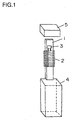
- FIG. 1 and FIG. 2 are exploded views showing the structure of exemplary resonance devices.
- numeral 1 denotes a core of magnetic materials, such as a ferrite, shaped in the form of an approximately plate or a rod
- 2 is a coil wound around said core
- 3 is a capacitor.
- the core, coil and capacitor are housed in a vessel 4 sealed tight with a cover 5 to be protected against the outside environments. Any material may be used for the vessel in so far as it is a non-magnetic material.
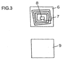
- FIG. 3 is an exploded view of a conventional electric resonator in a film shape.
- the conventional electric resonator is disposed on a base film 6 and a coil 7 made from metal foil adhered thereon, the coil 7 being coupled with a chip capacitor 8.
- Coil 7 may be made instead through printing of a conductive paste, or similar methods.
- the invented resonance device uses the magnetic core 1, and has sufficient spare space available. Therefore, the number of coil turns may be increased for obtaining a large impedance, also a capacitor 3 of larger capacitance may be used. Thus the resonance frequency of the resonance device may be substantially lowered, as compared with the case of conventional electric resonators.
- core 1 in the resonance device enables the ability to concentrate and select the high frequency magnetic flux of the transmitting wave, and to increase the signal.
- an invented resonance device can take a large value in the ⁇ and the Q in the formula (1). Namely, a great power may be detected and a capacitor of large capacitance can be used. As a result, the power of the transmitting wave can be stored for a certain period of time. Therefore, an invented resonance device can keep oscillating electromagnetic wave of the resonance frequency for a certain period of time after the transmitting wave is suspended.
- the invented detection apparatus has a feature, as described later, that as soon as a transmitting wave is transmitted the oscillation of the transmitting wave is immediately discontinued so as , to be ready to receive a wave spontaneous attenuation in accordance with the LC circuit constant does not occur.
- the resonance device that has received a transmitting wave continues to oscillate a responding electromagnetic wave for a certain period of time even after the detection apparatus suspends transmitting its transmitting wave.
- the resonance frequency of the resonance device may be set at an interval of approximately 30kHz, starting from 90kHz up to the bottom of the commercial broadcasting frequency band, 480kHz.
- a detection apparatus is composed of a transmitting section for transmitting an electromagnetic wave of the resonance frequency of the resonance device, and a receiving section for detecting an electromagnetic wave from the resonance device.
- the detection apparatus is described in detail referring to FIG. 4.
- FIG. 4 is a block diagram of a detection apparatus in accordance with an exemplary embodiment of the present invention.
- numeral 23 denotes a microprocessor for controlling the entire system (hereinafter referred to as MPU)
- 11 is a direct digital synthesizer for transmitting an electromagnetic wave of the resonance frequency of resonance device, as well as transmitting an electromagnetic wave of a frequency that is identical to the difference between the resonance frequency and the intermediate frequency (hereinafter referred to as DDS)
- 12 is an alternating switch for switching the transmitting/receiving
- 13 is a transmitting amplifier
- 14 is a transmitting antenna
- 15 is the tuning capacitors where an optimum capacitor is selected corresponding to a transmitting frequency
- 16 is a discharge resistor for forcedly ending a transmission at the end of the transmission
- 17 is a receiving antenna
- 18 is the receiving tuning capacitors where an optimum capacitor is selected corresponding to a receiving frequency
- 19 is a receiving amplifier
- 20 is a frequency converter for converting a receiving signal into
- DDS 11 oscillates a resonance frequency f1 of the resonance device 10.
- the oscillated signal is sent to the alternating switch 12, and amplified at the transmitting amplifier 13 to be transmitted from the transmitting antenna 14.
- a capacitor suitable to the resonance frequency f1 is connected in series to one of the terminals of the transmitting antenna 14. The capacitor is selected in accordance with instructions from MPU 23.
- the transmitting wave is received by the resonance device 10, and an electric resonance is created if the resonance frequency f1 is within a resonance range of the resonance device 10.
- the detection apparatus is switched to a receiving state.
- the discharge resistor 16 is put into operation to attenuate the transmitting output within a short period of time.
- a receiving tuning capacitor 18 matching the resonance frequency f1 is selected and is connected to one of the terminals of the receiving antenna 17.
- An electromagnetic wave having the frequency identical to the difference between an intermediate frequency fc and the resonance frequency f1 is oscillated from the DDS 11 to be mixed at the frequency converter 20.
- the alternating switch 12 is switched to a receiving state.
- An echo signal transmitted from the resonance device 10 is received by the receiving antenna 17 and amplified at the receiving amplifier 19.
- the amplified echo signal is converted at the frequency converter 20 into an intermediate frequency, and sent via the filter 21 to the amplifier and detector 22 to be detected as a signal received.
- the signal received and detected is delivered to the MPU 23 through an input terminal of an A/D converter for processing.
- the detection apparatus uses a DDS 11 both for the transmitting and for the receiving. While a transmitting section of the detection apparatus is on duty of transmission, a receiving section is out of duty staying in a waiting state. Therefore, the receiving sector typically is not saturated with the transmitted wave; it immediately becomes ready for receiving as soon as it is switched to a receiving state from a transmitting state.
- the detection apparatus converts the received signal into an intermediate frequency by a heterodyne process and delivers it through a filter circuit for the amplification and detection in order to distinguish signals from the resonance device 10 having a plurality of resonance frequencies.
- a filter circuit for the amplification and detection in order to distinguish signals from the resonance device 10 having a plurality of resonance frequencies.
- the detection apparatus is able to detect a targeted signal without being affected by a transmitting wave oscillated by itself. Therefore, even a resonance device is located in a place away from a detection apparatus the information can be exchanged with a high accuracy.
- the directional characteristics are also improved along with the use of an antenna to be referred to later.
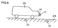
- a system for controlling a moving vehicle using the resonance device and the detection apparatus is described as a third exemplary embodiment of the present invention. The description is made below referring to FIG. 6.
- the present control system for a moving vehicle comprises a resonance device 10 of embodiment 1 buried under a road 24, and a detection apparatus of embodiment 2 installed on a vehicle 25.
- the vehicle 25 having the detection apparatus receives an echo wave transmitted from the resonance device 10 and detects it for obtaining the road information or the driving information.
- a transmitting antenna 14 on the vehicle 25 transmits an electromagnetic wave of a certain resonance frequency specific to the resonance device 10 one after another. If the resonance device 10 is located in a place within reach of the electromagnetic wave transmitted, the resonance device 10 transmits an echo wave.
- a receiving antenna 17 on the vehicle 25 receives the echo wave, which is detected by the detection apparatus on board.
- the detection apparatus acquires information about the relative relationship between the vehicle and the road. The information is accumulated in the detection apparatus to be used as information for the automatic driving of a vehicle.
- Each of the transmitting antenna 14 and the receiving antenna 17 of the detection apparatus is provided with tuning capacitors 15, 18 respectively. Therefore, the resonance device 10 may be classified into a plurality of categories of different resonance frequencies, in order to obtain different information from them.
- An office of road administration can make road information available for a moving vehicle, by placing the resonance devices 10 having different resonance frequencies in a road in a continual arrangement with a certain interval relative to each other. Or, different information may be provided with one resonance device 10.
- an office of road administration can provide a desirably safe and sure system for moving vehicles.
- the durability of the resonance device 10 can be improved as compared to a case where such a device is mounted on a side wall, etc. of a road.
- a transmitting antenna and a receiving antenna have been provided independently one for one in the above description, a plurality of receiving antennas may be provided for one transmitting antenna.
- the resonance device 10 can be placed at a location such as a side wall if the complete packaging can be made.
Landscapes
- Physics & Mathematics (AREA)
- General Physics & Mathematics (AREA)
- Geophysics And Detection Of Objects (AREA)
- Near-Field Transmission Systems (AREA)
- Length-Measuring Devices Using Wave Or Particle Radiation (AREA)
- Traffic Control Systems (AREA)
- Radar Systems Or Details Thereof (AREA)
- Measurement Of Length, Angles, Or The Like Using Electric Or Magnetic Means (AREA)
- Train Traffic Observation, Control, And Security (AREA)
Applications Claiming Priority (2)
| Application Number | Priority Date | Filing Date | Title |
|---|---|---|---|
| JP10080847A JPH11283178A (ja) | 1998-03-27 | 1998-03-27 | 電気共振識別子、電気共振識別子検出装置および交通システム |
| JP8084798 | 1998-03-27 |
Publications (3)
| Publication Number | Publication Date |
|---|---|
| EP0945839A2 true EP0945839A2 (de) | 1999-09-29 |
| EP0945839A3 EP0945839A3 (de) | 2000-11-15 |
| EP0945839B1 EP0945839B1 (de) | 2004-11-03 |
Family
ID=13729754
Family Applications (1)
| Application Number | Title | Priority Date | Filing Date |
|---|---|---|---|
| EP99105109A Expired - Lifetime EP0945839B1 (de) | 1998-03-27 | 1999-03-25 | Elektrisches Resonanzelement, Vorrichtung zur Detektion und Verfahren zur Steuerung eines beweglichen Fahrzeugs |
Country Status (4)
| Country | Link |
|---|---|
| US (1) | US6518884B1 (de) |
| EP (1) | EP0945839B1 (de) |
| JP (1) | JPH11283178A (de) |
| DE (1) | DE69921527T2 (de) |
Cited By (1)
| Publication number | Priority date | Publication date | Assignee | Title |
|---|---|---|---|---|
| WO2012155347A1 (en) * | 2011-05-18 | 2012-11-22 | Siemens Aktiengesellschaft | Metal detection system and metal detector |
Families Citing this family (12)
| Publication number | Priority date | Publication date | Assignee | Title |
|---|---|---|---|---|
| AU2001217746A1 (en) * | 1998-05-14 | 2002-05-27 | Calypso Medical, Inc. | Systems and methods for locating and defining a target location within a human body |
| US6363940B1 (en) * | 1998-05-14 | 2002-04-02 | Calypso Medical Technologies, Inc. | System and method for bracketing and removing tissue |
| US7135978B2 (en) * | 2001-09-14 | 2006-11-14 | Calypso Medical Technologies, Inc. | Miniature resonating marker assembly |
| US7289839B2 (en) * | 2002-12-30 | 2007-10-30 | Calypso Medical Technologies, Inc. | Implantable marker with a leadless signal transmitter compatible for use in magnetic resonance devices |
| US8196589B2 (en) * | 2003-12-24 | 2012-06-12 | Calypso Medical Technologies, Inc. | Implantable marker with wireless signal transmitter |
| CN101919110A (zh) | 2008-01-11 | 2010-12-15 | 木加哈特控股公司 | 使用铁氧体芯增强去往/来自无源id电路的能量传递效率 |
| US8395525B2 (en) * | 2008-02-25 | 2013-03-12 | Magnet Consulting, Inc. | Extending the read range of passive RFID tags |
| US8395507B2 (en) | 2008-04-21 | 2013-03-12 | Magnet Consulting, Inc. | H-field shaping using a shorting loop |
| DE102013018564B4 (de) * | 2013-11-05 | 2018-04-05 | Gea Tuchenhagen Gmbh | Ventilsteuereinrichtung und Prozessventil |
| JP2018198372A (ja) * | 2017-05-23 | 2018-12-13 | 京セラ株式会社 | 電子機器 |
| JP7226587B2 (ja) * | 2019-11-26 | 2023-02-21 | 愛知製鋼株式会社 | 磁気マーカ |
| US11630964B1 (en) | 2021-11-24 | 2023-04-18 | Fortiss, Llc | De-tuned multiple RFID antenna arrangement for gaming |
Family Cites Families (18)
| Publication number | Priority date | Publication date | Assignee | Title |
|---|---|---|---|---|
| US3740742A (en) * | 1971-05-11 | 1973-06-19 | T Thompson | Method and apparatus for actuating an electric circuit |
| US3895368A (en) * | 1972-08-09 | 1975-07-15 | Sensormatic Electronics Corp | Surveillance system and method utilizing both electrostatic and electromagnetic fields |
| US4361202A (en) * | 1979-06-15 | 1982-11-30 | Michael Minovitch | Automated road transportation system |
| JPS56111993A (en) * | 1980-02-07 | 1981-09-04 | Meisei Electric Co Ltd | Abnormality detector for pressure in tire |
| US4609911A (en) * | 1983-07-05 | 1986-09-02 | Minnesota Mining And Manufacturing Company | Variable frequency RF electronic surveillance system |
| US4712094A (en) * | 1986-05-29 | 1987-12-08 | Minnesota Mining And Manufacturing Company | Self-orienting passive marker structure |
| SE469673B (sv) * | 1992-01-20 | 1993-08-16 | Rso Corp | Saett och anordning vid beroeringsfri avkaenning av objekt |
| SE508322C2 (sv) * | 1994-02-07 | 1998-09-28 | Leif Aasbrink | Larmelement |
| JP3467068B2 (ja) * | 1994-03-03 | 2003-11-17 | 明星電気株式会社 | 車両の危険走行警報システム及びこれに使用する応答体と警報装置 |
| US5661470A (en) * | 1994-03-04 | 1997-08-26 | Karr; Gerald S. | Object recognition system |
| US5499015A (en) * | 1994-09-28 | 1996-03-12 | Sensormatic Electronics Corp. | Magnetomechanical EAS components integrated with a retail product or product packaging |
| US5506584A (en) * | 1995-02-15 | 1996-04-09 | Northrop Grumman Corporation | Radar sensor/processor for intelligent vehicle highway systems |
| DE19509999C2 (de) * | 1995-03-22 | 1998-04-16 | David Finn | Verfahren und Vorrichtung zur Herstellung einer Transpondereinheit sowie Transpondereinheit |
| US5517179A (en) * | 1995-05-18 | 1996-05-14 | Xlink Enterprises, Inc. | Signal-powered frequency-dividing transponder |
| JPH09298477A (ja) * | 1995-06-29 | 1997-11-18 | Sony Corp | 短波受信機およびローパスフィルタ |
| US5748085A (en) * | 1996-04-15 | 1998-05-05 | Davis; Dennis W. | Electronic article surveillance event monitoring system |
| US5955951A (en) * | 1998-04-24 | 1999-09-21 | Sensormatic Electronics Corporation | Combined article surveillance and product identification system |
| US6049279A (en) * | 1999-01-04 | 2000-04-11 | Minarovic; Joe T. | Detectable transponder conduit end cap |
-
1998
- 1998-03-27 JP JP10080847A patent/JPH11283178A/ja active Pending
-
1999
- 1999-03-25 EP EP99105109A patent/EP0945839B1/de not_active Expired - Lifetime
- 1999-03-25 DE DE69921527T patent/DE69921527T2/de not_active Expired - Fee Related
- 1999-03-29 US US09/272,776 patent/US6518884B1/en not_active Expired - Fee Related
Cited By (1)
| Publication number | Priority date | Publication date | Assignee | Title |
|---|---|---|---|---|
| WO2012155347A1 (en) * | 2011-05-18 | 2012-11-22 | Siemens Aktiengesellschaft | Metal detection system and metal detector |
Also Published As
| Publication number | Publication date |
|---|---|
| EP0945839B1 (de) | 2004-11-03 |
| DE69921527T2 (de) | 2005-03-24 |
| EP0945839A3 (de) | 2000-11-15 |
| US6518884B1 (en) | 2003-02-11 |
| DE69921527D1 (de) | 2004-12-09 |
| JPH11283178A (ja) | 1999-10-15 |
Similar Documents
| Publication | Publication Date | Title |
|---|---|---|
| US6518884B1 (en) | Electric resonance element, detection apparatus and moving vehicle control system | |
| EP0875050B1 (de) | Magnetomechanisches elektronisches warenüberwachungssystem mit pulsiertem signal und sendeantennendämpfung | |
| FI98573C (fi) | Läheisyysdetektori | |
| US5373301A (en) | Transmit and receive antenna having angled crossover elements | |
| EP0186483A2 (de) | Abfrage-Antwortsystem | |
| KR970026572A (ko) | 자동차 도난 방지 시스템 | |
| EP0262994B1 (de) | System, um den Diebstahl einer Ware zu entdecken | |
| EP0884707B1 (de) | Erfassungsgerät für magnetostriktive Resonatoren und Verkehrssystem | |
| JP2000353974A (ja) | 送受信装置 | |
| EP1548876A2 (de) | Antenne mit nanokristallinem Kern für EAS- und RFID-Anwendungen | |
| DE69015668D1 (de) | Ladendiebstahlnachweissystem vom Transmissionstyp. | |
| EP0919974B1 (de) | Verfahren und Gerät zur Detektion von magnetostriktiven Resonatoren sowie Verkehrssystem | |
| EP0899702B1 (de) | Magnetostriktiver Resonator, Strasse, in der dieser eingebettet ist und Verfahren zu dessen Einbettung | |
| JPH11149314A (ja) | 信号検出装置及びこれを用いた交通システム | |
| JPH09212761A (ja) | 被監視装置および監視装置 | |
| JP4550536B2 (ja) | レーダ装置 | |
| JP2000339582A (ja) | 電気共振あるいは磁歪共振マーカの検出装置及び交通システム | |
| JPH08138160A (ja) | 盗難防止装置 | |
| JP3103477B2 (ja) | 患者等の検出装置 | |
| KR200252130Y1 (ko) | 도난방지시스템용 표시기 | |
| JP2001356156A (ja) | 電磁波方式レーンマーカ統合検出装置 | |
| JPH07121786A (ja) | 患者等の検出装置 | |
| JP2002314457A (ja) | 無線式データキャリアシステムの送受信装置 | |
| JPH08222935A (ja) | 盗難防止装置用アンテナ | |
| JPH07110371A (ja) | レーダ電波検出装置 |
Legal Events
| Date | Code | Title | Description |
|---|---|---|---|
| PUAI | Public reference made under article 153(3) epc to a published international application that has entered the european phase |
Free format text: ORIGINAL CODE: 0009012 |
|
| AK | Designated contracting states |
Kind code of ref document: A2 Designated state(s): DE FR |
|
| AX | Request for extension of the european patent |
Free format text: AL;LT;LV;MK;RO;SI |
|
| PUAL | Search report despatched |
Free format text: ORIGINAL CODE: 0009013 |
|
| AK | Designated contracting states |
Kind code of ref document: A3 Designated state(s): AT BE CH CY DE DK ES FI FR GB GR IE IT LI LU MC NL PT SE |
|
| AX | Request for extension of the european patent |
Free format text: AL;LT;LV;MK;RO;SI |
|
| 17P | Request for examination filed |
Effective date: 20001222 |
|
| AKX | Designation fees paid |
Free format text: DE FR |
|
| 17Q | First examination report despatched |
Effective date: 20030403 |
|
| GRAP | Despatch of communication of intention to grant a patent |
Free format text: ORIGINAL CODE: EPIDOSNIGR1 |
|
| GRAS | Grant fee paid |
Free format text: ORIGINAL CODE: EPIDOSNIGR3 |
|
| GRAA | (expected) grant |
Free format text: ORIGINAL CODE: 0009210 |
|
| AK | Designated contracting states |
Kind code of ref document: B1 Designated state(s): DE FR |
|
| REF | Corresponds to: |
Ref document number: 69921527 Country of ref document: DE Date of ref document: 20041209 Kind code of ref document: P |
|
| ET | Fr: translation filed | ||
| PLBE | No opposition filed within time limit |
Free format text: ORIGINAL CODE: 0009261 |
|
| STAA | Information on the status of an ep patent application or granted ep patent |
Free format text: STATUS: NO OPPOSITION FILED WITHIN TIME LIMIT |
|
| PG25 | Lapsed in a contracting state [announced via postgrant information from national office to epo] |
Ref country code: DE Free format text: LAPSE BECAUSE OF NON-PAYMENT OF DUE FEES Effective date: 20051001 |
|
| 26N | No opposition filed |
Effective date: 20050804 |
|
| PG25 | Lapsed in a contracting state [announced via postgrant information from national office to epo] |
Ref country code: FR Free format text: LAPSE BECAUSE OF NON-PAYMENT OF DUE FEES Effective date: 20050331 |
|
| REG | Reference to a national code |
Ref country code: FR Ref legal event code: ST Effective date: 20110131 |