EP0945960B1 - Appareil d'alimentation avec enclenchement automatique après défaut d'alimentation - Google Patents
Appareil d'alimentation avec enclenchement automatique après défaut d'alimentation Download PDFInfo
- Publication number
- EP0945960B1 EP0945960B1 EP99302382A EP99302382A EP0945960B1 EP 0945960 B1 EP0945960 B1 EP 0945960B1 EP 99302382 A EP99302382 A EP 99302382A EP 99302382 A EP99302382 A EP 99302382A EP 0945960 B1 EP0945960 B1 EP 0945960B1
- Authority
- EP
- European Patent Office
- Prior art keywords
- power
- switch
- power source
- electrical power
- electromagnetic switch
- Prior art date
- Legal status (The legal status is an assumption and is not a legal conclusion. Google has not performed a legal analysis and makes no representation as to the accuracy of the status listed.)
- Expired - Lifetime
Links
Images




Classifications
-
- H—ELECTRICITY
- H02—GENERATION; CONVERSION OR DISTRIBUTION OF ELECTRIC POWER
- H02J—ELECTRIC POWER NETWORKS; CIRCUIT ARRANGEMENTS OR SYSTEMS FOR SUPPLYING OR DISTRIBUTING ELECTRIC POWER; SYSTEMS FOR STORING ELECTRIC ENERGY
- H02J9/00—Circuit arrangements for emergency or stand-by power supply, e.g. for emergency lighting
- H02J9/04—Circuit arrangements for emergency or stand-by power supply, e.g. for emergency lighting in which the distribution system is disconnected from the normal source and connected to a standby source
- H02J9/06—Circuit arrangements for emergency or stand-by power supply, e.g. for emergency lighting in which the distribution system is disconnected from the normal source and connected to a standby source with automatic change-over, e.g. UPS systems
-
- H—ELECTRICITY
- H10—SEMICONDUCTOR DEVICES; ELECTRIC SOLID-STATE DEVICES NOT OTHERWISE PROVIDED FOR
- H10P—GENERIC PROCESSES OR APPARATUS FOR THE MANUFACTURE OR TREATMENT OF DEVICES COVERED BY CLASS H10
- H10P95/00—Generic processes or apparatus for manufacture or treatments not covered by the other groups of this subclass
Definitions
- the present invention relates to a power supply system for supplying power to an apparatus, see e.g. US-A-5,412,528.
- a semiconductor fabrication plant for fabricating semiconductor devices has a clean room containing a number of fabrication apparatuses, e.g., various processing apparatuses for fabrication steps such as lithography, testing apparatuses, and transfer apparatuses.
- the plant also has a power supply system for supplying power for operating these various apparatuses.
- This power supply system includes an installed power source for transforming commercial electric power supplied from an electric power company outside the plant and supplying the transformed power into the plant.
- an operator operates a power ON switch to start supplying power to the fabrication apparatus to activate it.
- the operator operates a power OFF switch to stop the supply of power from the installed power source to the fabrication apparatus to thereby stop the apparatus.
- an emergency stop switch operable by an operator is usually arranged near the apparatus.
- an emergency stop circuit EMO
- EMO operates to shut off power supply from the installed power source to all apparatuses such as a fabrication apparatus, air conditioner, and light source, thereby urgently stopping these apparatuses.
- the system may run away from the control when reactivated.
- the present invention has been made in consideration of the above situation, and is concerned to provide fabrication arrangements capable of achieving high safety and high productivity at the same time.
- a power supply apparatus according to claim 1 is provided.
- Fig. 1 is a view showing the arrangement of a semiconductor device fabrication apparatus according to the first embodiment of the present invention.
- an installed power source 23 of a fabrication plant supplies power to the fabrication apparatus.
- This installed power source 23 includes a main power source and a backup power source.
- the main power source transforms commercial electric power supplied from an electric power company to the semiconductor fabrication plant and supplies the transformed power to individual apparatuses in the plant.
- the backup power source supplies power into the factory instead of the main power source.
- This backup power source has an independent power generator such as a diesel generator.
- the semiconductor fabrication apparatus is roughly divided into a fabrication apparatus main body 1, a main body power source 6, a constant temperature chamber 2, an air conditioner 3, a main body controller 4, and a power supply unit 5.
- the constant temperature chamber 2 contains the fabrication apparatus main body 1 and keeps it in a fixed environment.
- the air conditioner 3 holds the ambient temperature, gas concentration, cleanness, and the like in the constant temperature chamber 2 constant.
- the main body controller 4 controls operations of the fabrication apparatus main body 1 and the air conditioner 3.
- the power supply unit 5 supplies or shuts off power from the installed power source 23 to the main body power source 6 and the air conditioner 3.
- the semiconductor fabrication apparatus is a semiconductor exposure apparatus for exposing a semiconductor wafer substrate.
- the present invention is similarly applicable to various processing apparatuses and testing apparatuses used in semiconductor fabrication.
- a light source 13 is installed separately from the chamber 2 containing the fabrication apparatus main body 1. This light source 13 supplies exposure light to the fabrication apparatus main body 1 through a beam line 20.
- the light source 13 is, e.g., an excimer laser source or an X-ray source (SR or plasma X-ray source).
- the power supply unit 6 supplies power to the light source 13 through a power cable 21.
- Acommunication cable 22 connects the light source 13 and the main body controller 4.
- Fig. 2 is a block diagram for explaining a power supply system of the power supply unit 5 in the semiconductor fabrication apparatus shown in Fig. 1.
- Power lines are formed from the installed power source 23 of the plant to the main body power source 6, the air conditioner 3, and the light source 13 via a main breaker 7 and a first electromagnetic switch 8 (a contactor including a contact 8a and an electromagnetic coil 8b for opening and closing the contact 8a) for turning on and off the power source.
- the upstream side (near the installed power source) and the down stream side (near the fabrication apparatus) of the contact 8a of the first electromagnetic switch 8 will be called a primary side and a secondary side, respectively.
- the primary side of the electromagnetic switch 8 is branched and connected to an overcurrent protector 9, an uninterruptible power source 10, an overcurrent protector 12, and a power source controller 11 as an emergency stop circuit in this order.
- the uninterruptible power source 10 incorporates an AC/DC converter, a battery, and a power failure detecting circuit 15 for detecting a power failure (an instantaneous power failure and power failure for a few seconds to a few tens of minutes).
- This power failure detecting circuit 15 outputs a detection signal to the main body controller 4 and the power source controller 11.
- the power source controller 11 is connected to a power ON switch 17a and a power OFF switch 17b.
- This power source controller 11 is also connected to an electromagnetic coil 14d of a second electromagnetic switch 14 (a relay including relay contacts 14a to 14c and 14e and the electromagnetic coil 14d for opening and closing these relay contacts 14a to 14c and 14e) for controlling power supply to the electromagnetic coil of the first electromagnetic switch 8.
- Two emergency stop switches 18a and 18b and a connecting terminal 19 to be opened and closed by an abnormal temperature detecting unit are inserted midway along the power line to the electromagnetic coil 14d.
- the emergency stop switches 18a and 18b are arranged in a portion of the outer wall of the constant temperature chamber 2 of the semiconductor fabrication apparatus where an operator readily accesses these switches.
- the second electromagnetic switch 14 has four relay contact systems (14a to 14c and 14e) to be simultaneously opened and closed.
- the first system (relay contact 14a) controls power supply to the electromagnetic coil of the first electromagnetic switch 8.
- the remaining three systems are the relay contacts 14b, 14c and 14e.
- the relay contact 14b supplies and shuts off electric power to the main body controller 4.
- the relay contact 14c connects and disconnects the signal line for transmitting a detection signal from the power failure detecting circuit 15 to the main body controller 4.
- the relay contact 14e is used for discriminating whether the cause of power shut down comes from an operation of the emergency stop switch or power failure.
- this power supply system includes the first electromagnetic switch 8 for supplying and shutting off power from the installed power source 23 to the individual apparatuses (exposure apparatus main body, air conditioner, and light source) and the second electromagnetic switch 14 for controlling power supply to the electromagnetic coil 8b of the first electromagnetic switch 8.
- Power is supplied to the electromagnetic coil 8b of the first electromagnetic switch 8 from the primary side of the first electromagnetic switch 8 via the relay contact 14a of the second electromagnetic switch 14.
- power is supplied to the electromagnetic coil 14d of the second electromagnetic switch 14 via the power source controller 11 as an emergency stop circuit.
- the emergency stop switches 18a and 18b are inserted midway along the power line to the electromagnetic coil 14d of the second electromagnetic switch 14.
- the first and second electromagnetic switches 8 and 14 include the relay contacts 8a, 14a to 14c and 14e which are open when no power is supplied to the electromagnetic coils 8b and 14d and closed when power is supplied to these electromagnetic coils 8b and 14d.
- the emergency stop switches 18a and 18b are normally closed to supply power. When activated, these emergency stop switches 18a and 18b are opened to shut off the power supply.
- Fig. 2 shows the states of the electromagnetic switches when the apparatuses are stopped.
- the uninterruptible power source 10 converts an AC divided on the primary side of the electromagnetic switch 8 into a DC of 24 V. This power is used to charge the built-in battery and also supplied to the power source controller 11 and the main body controller 4.
- Fig. 6 is a block diagram showing details of the arrangement of the main body controller 4.
- a CPU 41 controls, e.g., the fabrication apparatus main body 1, the air conditioner 3, the main body power supply unit 6, and the light source 13 by executing control programs stored in a ROM 42.
- a RAM 43 provides a work area when the CPU 41 executes these control programs.
- An operation unit 44 includes operation switches for, e.g., activating and stopping the fabrication apparatus, indicators for indicating the operating state of the apparatus, and the like.
- An I/O interface 45 transmits a driving signal from the CPU 41 to a driving apparatus. As shown in Fig. 2, the installed power source 23 supplies power to the driving system, and the power source controller 11 (the uninterruptible power source 10) supplies power to the main body controller 4.
- an operator presses the power ON switch 17a to allow the power source controller 11 to supply power from the uninterruptible power source 10 to the coil 14d of the second electromagnetic switch 14 (relay). Since the relay contact 14a of the second electromagnetic switch 14 is closed, power is supplied to the coil 8b of the first electromagnetic switch 8. Simultaneously the relay contact 14b closes to supply power to the main body controller 4. Consequently, the relay contact 8a is closed to supply power from the installed power source 23. In this state, the operator presses the activation switch on the operation unit 44 to allow the fabrication apparatus to start operating.
- the operator To stop the apparatus, the operator first presses the stop switch on the operation unit 44 to shift the apparatus from an operating state to a stop state. After that, the operator presses the power OFF switch 17b to shut off the power supply from the power source controller 11. Consequently, the relay contact 14a opens to shut off the power supply to the coil 8b of the first electromagnetic switch 8. This opens the relay contact 8a to shut off the power supply from the installed power source 23.
- a signal from the power failure detecting circuit 15 is disabled when the relay contact 14c of the second electromagnetic switch 14 opens. In the case of emergency stop, therefore, the power supply from the installed power source 23 to the apparatus is completely shut off except for the primary side of the first electromagnetic switch 8 as a power shut-off device and the power source controller 11 as an emergency stop circuit. Accordingly, high safety can be maintained.
- the power source controller 11 can detect emergency stop.
- the power source controller 11 stops the supply from the uninterruptible power source until the start switch 17a is again pressed.
- the apparatus cannot be reactivated unless the operator again presses the power ON switch 17a to turn on the power source. Consequently, the safety can be improved.
- the power supply to the main body controller 4 is also shut off, so the CPU 41 of the main body 4 is initialized. Therefore, a normal initialization procedure is necessary to recover the apparatus.
- the power source controller 11 and the main body controller 4 include built-in timers. If the power failure detecting circuit 15 detects recovery from a power failure within a predetermined time (e.g., seven seconds) after detecting the power failure, the apparatus is automatically reactivated. If power failure continues over the predetermined time set in the timer, the fabrication apparatus main body 1, the air conditioner 3, and the light source 13 are not automatically reactivated even when the power failure detecting circuit 15 detects recovery from the power failure after that. As when the emergency stop circuit operates, the apparatus is not reactivated unless the operator operates the power switch.
- the predetermined time of the timer by which whether reactivation is possible is determined can be freely set from a fraction of a second to a few tens of minutes.
- the air conditioner 3 In reactivating the apparatus, it is also possible to first reactivate the air conditioner 3 and then automatically reactivate the semiconductor fabrication apparatus main body 1 and the light source 13.
- the air conditioner 3 is preferentially reactivated because this air conditioner 3 requires the longest time to return the environment in the constant temperature chamber 2 to a steady state.
- Fig. 7 is a flow chart for explaining processes of activation, stop, and emergency stop. Control programs for realizing these processes are stored in the ROM 42.
- this apparatus When an operator presses the activation switch on the operation unit 44, this apparatus is activated (steps S101 and S102). It should be evident to those skilled in the art that supply of the installed power source, initial positions of individual devices, and variation activation conditions are checked in these steps.
- the CPU 41 monitors an operation of the stop switch on the operation unit 44 or a power failure detection signal from the power failure detecting circuit 15. If the stop switch is operated, the CPU 41 stops the apparatus (steps S103 and S109).
- the CPU 41 saves operation information such as parameters of apparatuses in operation into the RAM 43 in order to prepare for automatic reactivation upon power recovery (steps S401 and S105). If the power is recovered within a predetermined time, the CPU 41 reactivates the apparatus by using the parameters saved in the RAM 43 (steps S106 to S108). If the CPU 41 reactivates the apparatus from the air conditioner as described above, the CPU 41 executes a preprogrammed predetermined reactivation process. If the power is not recovered within the predetermined time, the flow advances to the stop process (steps S106 and S109).
- Fig. 8 is a flow chart for explaining the operation of the power source controller.
- the CPU 41 monitors the power OFF switch 17b, occurrence of emergency stop, and occurrence of a power failure. If the power OFF switch 17b is pressed or the relay contact 14e opens to detect emergency stop, the power source controller 11 stops power supply (steps S203, S204, and S208).
- the power source controller 11 keeps supplying power if the power is recovered within a predetermined time (steps S206 and S207). If the power is not recovered within the predetermined time, the power source controller 11 stops power supply (steps S206, S207, and S208).
- the above procedure of the power source controller 11 can be realized by using relay circuits and the like or a microcomputer. In either case, the circuit configuration is obvious to those skilled in the art.
- the built-in battery of the uninterruptible power source 10 has enough capacity to continuously supply power to the power source controller 11 and the main body controller 4 for amaximum of 20 minutes required for the installed power source 23 to switch from the commercial power source to the independent power generator when a power failure occurs.
- the installed power source includes an independent power generator such as a diesel generator as a backup power source.
- a predetermined initialization time (usually about 10 minutes) is required to activate the independent power generator, so power supply is stopped during a switching period in which the power source stops and the backup power source starts supplying power.
- the built-in battery of the uninterruptible power source 10 has enough capacity to supply power for a time (e.g., 20 minutes) longer than this switching period (e.g., 10 minutes).
- Fig. 3 shows the arrangement of this modification.
- the same reference numerals as in Fig. 1 denote the same parts in Fig. 3, and a detailed description thereof will be omitted.
- reference numeral 24 denotes an installed uninterruptible power source of a plant; and 51, an uninterruptible power source box which includes a circuit for converting a DC supplied from the installed uninterruptible power source 24 into a DC of 24 V.
- this embodiment has described a semiconductor fabrication apparatus including an emergency stop circuit which is an emergency stop switch.
- a controller automatically reactivates the semiconductor fabrication apparatus after the power is recovered. If the emergency stop circuit stops the operation of the semiconductor fabrication apparatus, the controller does not automatically reactivate the semiconductor fabrication apparatus.
- this embodiment is a power supply apparatus of a fabrication apparatus having an emergency stop function using an emergency stop switch.
- the power supply apparatus automatically resupplies power to the fabrication apparatus after the power is recovered. If the emergency stop function stops the operation of the fabrication apparatus, the power supply apparatus does not automatically resupply power to the fabrication apparatus.
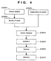
- Fig. 4 shows the flow of fabrication of a microdevice (e.g., a semiconductor chip such as an IC or LSI, liquid crystal panel, CCD, thin-film magnetic head, or micromachine) .
- a microdevice e.g., a semiconductor chip such as an IC or LSI, liquid crystal panel, CCD, thin-film magnetic head, or micromachine
- step 1 circuit design
- step 2 making of mask
- a mask having the designed pattern is made.
- step 3 fabric of wafer
- Step 4 wafer process
- Step 5 is called a post-process in which the wafer fabricated in step 4 is formed into semiconductor chips.
- This step 5 includes steps such as an assembly step (dicing and bonding) and a packaging step (chip encapsulation).
- step 6 tests such as an operation test and a durability test of the fabricated semiconductor devices are performed.
- the semiconductor devices are completed through these steps and shipped (step 7) .
- Fig. 5 shows details of the above wafer process flow.
- step 11 oxidation
- step 12 CVD
- step 13 formation of electrodes
- step 14 ion implantation
- step 15 resist processing
- step 16 exposure
- step 17 development
- step 18 etching
- step 19 resist removal
- the resist which is unnecessary after the etching is removed.
- multiple circuit patterns are formed on the wafer.
- the present invention can achieve high safety and high productivity at the same time. For example, to urgently stop a fabrication apparatus in operation, the apparatus can be stopped while runaway of the system is prevented. Also, even when power supply is stopped owing to an unexpected cause such as a power failure or power source failure, the time required to restart the operation can be reduced without lowering the safety.
Landscapes
- Business, Economics & Management (AREA)
- Emergency Management (AREA)
- Engineering & Computer Science (AREA)
- Power Engineering (AREA)
- Exposure And Positioning Against Photoresist Photosensitive Materials (AREA)
- Stand-By Power Supply Arrangements (AREA)
Claims (16)
- Appareil d'alimentation en énergie électrique comportant :caractérisé en ce qu'il comporte :un premier commutateur électromagnétique (8) destiné à connecter une première source (23) d'énergie électrique à un appareil (3, 6, 13) et à l'en déconnecter, ledit premier commutateur électromagnétique comportant des premiers contacts (8a) et un premier actionneur (8b) pour fermer les premiers contacts (8a) lorsque de l'énergie est fournie à l'actionneur (8b) ; etun premier circuit (7, 9, 10, 14a, 51) destiné à fournir de l'énergie électrique audit premier actionneur (8b) dudit premier commutateur électromagnétique (8),un second commutateur électromagnétique (14) comportant des seconds contacts (14a) destinés à fermer et ouvrir ledit premier circuit, et un second actionneur (14d) destiné à fermer lesdits seconds contacts (14a) lorsque de l'énergie est fournie audit second actionneur (14d) ;un second circuit (11, 51) destiné à fournir de l'énergie électrique audit second actionneur (14d) dudit second commutateur électromagnétique (14) à partir d'une source (10, 24) d'énergie électrique non interruptible ; etun commutateur (18a, 18b) manoeuvré manuellement, destiné à ouvrir ledit second circuit.
- Appareil selon la revendication 1, dans lequel ledit commutateur (18a, 18b) manoeuvré manuellement est normalement fermé, et est ouvert lorsqu'il est manoeuvré manuellement.
- Appareil selon la revendication 1, dans lequel ledit second circuit comporte en outre un contact (19) qui s'ouvre lorsqu'une erreur de l'appareil est détectée.
- Appareil selon la revendication 1, dans lequel la source d'énergie électrique non interruptible (10, 24) comprend une batterie.
- Appareil selon la revendication 1, dans lequel la première source d'énergie électrique fournit de l'énergie alternative, et ladite source d'énergie électrique non interruptible est conçue pour fournir de l'énergie continue.
- Appareil selon la revendication 1, dans lequel ledit premier circuit fournit de l'énergie électrique audit premier commutateur électromagnétique (8) depuis ladite première source d'énergie électrique (23, 7, 9, 14a (figure 2)).
- Appareil selon la revendication 1, dans lequel chacun desdits premier et second commutateurs électromagnétiques (8, 8a, 14, 14a) est ouvert lorsqu'aucune énergie électrique n'est fournie à son actionneur (8b, 14d) et est fermé lorsque de l'énergie électrique lui est fournie.
- Appareil selon la revendication 1, comportant en outre un commutateur (14b) enclenché avec ledit second commutateur électromagnétique pour connecter la source d'énergie électrique non interruptible à un dispositif de commande (4) situé dans l'appareil et l'en déconnecter.
- Appareil selon la revendication 1, comportant en outre une unité de commande (11) destinée à commander l'alimentation en énergie électrique dudit second commutateur électromagnétique.
- Appareil selon la revendication 9, dans lequel ledit commutateur manoeuvré manuellement ouvre ledit second circuit entre ladite unité de commande et ledit second commutateur électromagnétique.
- Appareil selon la revendication 9, comportant en outre un commutateur (17a) de mise sous tension manoeuvré manuellement et un commutateur (17b) de mise hors tension manoeuvré manuellement, dans lequel ladite unité de commande commande la fourniture d'énergie électrique audit second commutateur électromagnétique sur la base des sorties dudit commutateur de mise sous tension manoeuvré manuellement et dudit commutateur de mise hors tension manoeuvré manuellement.
- Appareil selon la revendication 9, comportant en outre une unité de détection (15) destinée à détecter une défaillance d'alimentation en énergie électrique depuis la première source d'énergie électrique, dans lequel ladite unité de commande maintient la fourniture d'énergie électrique audit second commutateur électromagnétique pendant un temps prédéterminé après que ladite unité de commande a détecté la défaillance (S206), et arrête ensuite la fourniture d'énergie électrique audit second commutateur électromagnétique (S208).
- Appareil selon la revendication 12, comportant en outre un moyen de réglage destiné à régler le temps prédéterminé.
- Appareil selon la revendication 12, dans lequel ladite unité de commande informe un dispositif de commande situé dans l'appareil que ladite unité de détection détecte la défaillance.
- Appareil selon la revendication 14, comportant en outre un commutateur (14c) enclenché avec ledit second commutateur électromagnétique pour ouvrir et fermer un trajet de transmission de signaux pour l'information par ladite unité de commande.
- Appareil selon la revendication 1, dans lequel ledit premier circuit fournit de l'énergie électrique audit premier commutateur électromagnétique (8) à partir de la source d'énergie électrique non interruptible (24, 7, 51 (figure 3)).
Applications Claiming Priority (2)
| Application Number | Priority Date | Filing Date | Title |
|---|---|---|---|
| JP10081379A JPH11285167A (ja) | 1998-03-27 | 1998-03-27 | 半導体デバイス等の製造装置と製造方法、ならびに電力供給システム |
| JP8137998 | 1998-03-27 |
Publications (3)
| Publication Number | Publication Date |
|---|---|
| EP0945960A2 EP0945960A2 (fr) | 1999-09-29 |
| EP0945960A3 EP0945960A3 (fr) | 2000-11-08 |
| EP0945960B1 true EP0945960B1 (fr) | 2005-10-12 |
Family
ID=13744677
Family Applications (1)
| Application Number | Title | Priority Date | Filing Date |
|---|---|---|---|
| EP99302382A Expired - Lifetime EP0945960B1 (fr) | 1998-03-27 | 1999-03-26 | Appareil d'alimentation avec enclenchement automatique après défaut d'alimentation |
Country Status (5)
| Country | Link |
|---|---|
| US (1) | US6304005B1 (fr) |
| EP (1) | EP0945960B1 (fr) |
| JP (1) | JPH11285167A (fr) |
| KR (1) | KR100318837B1 (fr) |
| DE (1) | DE69927631T2 (fr) |
Cited By (1)
| Publication number | Priority date | Publication date | Assignee | Title |
|---|---|---|---|---|
| TWI424464B (zh) * | 2003-08-29 | 2014-01-21 | 尼康股份有限公司 | A liquid recovery device, an exposure device, an exposure method, and an element manufacturing method |
Families Citing this family (23)
| Publication number | Priority date | Publication date | Assignee | Title |
|---|---|---|---|---|
| JPWO2002054464A1 (ja) * | 2000-12-28 | 2004-05-13 | 株式会社ニコン | 露光方法及び露光装置 |
| KR20030054587A (ko) * | 2001-12-26 | 2003-07-02 | 동부전자 주식회사 | 전원 공급 시스템 |
| US6902107B2 (en) * | 2002-01-28 | 2005-06-07 | Datacard Corporation | Card personalization system and method |
| US7545053B2 (en) * | 2002-09-04 | 2009-06-09 | Hitachi, Ltd. | Power supply and power supply method upon interruption of electric service |
| KR100722753B1 (ko) * | 2002-09-13 | 2007-05-30 | 동경 엘렉트론 주식회사 | 회전 구동 장치 및 회전 구동 방법 |
| US7352085B2 (en) * | 2003-08-12 | 2008-04-01 | Hewlett-Packard Development Company, L.P. | Disconnection of electronic device from power source |
| US7411653B2 (en) | 2003-10-28 | 2008-08-12 | Asml Netherlands B.V. | Lithographic apparatus |
| US8902568B2 (en) | 2006-09-27 | 2014-12-02 | Covidien Lp | Power supply interface system for a breathing assistance system |
| US7847683B2 (en) * | 2007-09-12 | 2010-12-07 | International Business Machines Corporation | Emergency machine off feature with safety control interface |
| US7962772B2 (en) | 2008-02-07 | 2011-06-14 | Ainet Registry, Llc | Backup power system and method |
| US8302600B2 (en) | 2008-09-30 | 2012-11-06 | Nellcor Puritan Bennett Llc | Battery management for a breathing assistance system |
| AU2009330055B2 (en) | 2008-12-23 | 2015-11-05 | Xoma (Us) Llc | Flexible manufacturing system |
| US8776790B2 (en) | 2009-07-16 | 2014-07-15 | Covidien Lp | Wireless, gas flow-powered sensor system for a breathing assistance system |
| US9795957B2 (en) | 2009-08-16 | 2017-10-24 | G-Con Manufacturing, Inc. | Modular, self-contained, mobile clean room |
| US9518748B2 (en) * | 2009-08-16 | 2016-12-13 | G-Con Manufacturing Inc. | Modular, self-contained, mobile clean room |
| CN102549879B (zh) | 2009-09-25 | 2014-09-03 | 东芝三菱电机产业系统株式会社 | 不间断供电电源装置 |
| US8547062B2 (en) | 2009-12-02 | 2013-10-01 | Covidien Lp | Apparatus and system for a battery pack assembly used during mechanical ventilation |
| CN102332749B (zh) * | 2010-12-31 | 2014-01-15 | 上海源致信息技术有限公司 | 控制设备及其电源管理装置及方法 |
| JP5579651B2 (ja) * | 2011-04-28 | 2014-08-27 | 三菱電機株式会社 | 制御装置、復電制御システム、及びプログラム |
| USD775345S1 (en) | 2015-04-10 | 2016-12-27 | Covidien Lp | Ventilator console |
| JP6907794B2 (ja) * | 2017-08-08 | 2021-07-21 | 富士電機株式会社 | 無停電電源装置 |
| AU2020329233B2 (en) | 2019-08-15 | 2022-07-07 | G-Con Manufacturing, Inc. | Removable panel roof for modular, self-contained, mobile clean room |
| US11492795B2 (en) | 2020-08-31 | 2022-11-08 | G-Con Manufacturing, Inc. | Ballroom-style cleanroom assembled from modular buildings |
Family Cites Families (8)
| Publication number | Priority date | Publication date | Assignee | Title |
|---|---|---|---|---|
| US4384213A (en) * | 1976-07-19 | 1983-05-17 | Westinghouse Electric Corp. | Automatic transfer control device |
| US4423336A (en) | 1982-05-17 | 1983-12-27 | Mcgraw-Edison Company | Electromechanically controlled automatic transfer switch and bypass switch assembly |
| CA1228119A (fr) | 1983-08-16 | 1987-10-13 | Tadao Shibuya | Source d'alimentation de secours en cas de panne de secteur |
| JPS6043026A (ja) | 1983-08-16 | 1985-03-07 | 株式会社明電舎 | インバ−タ制御装置 |
| DE4223435C2 (de) | 1992-05-22 | 1994-06-01 | Ferag Ag | Sicherheitsabschaltsystem |
| DE19540069A1 (de) | 1995-10-27 | 1997-04-30 | Elan Schaltelemente Gmbh | Anordnung zur Erfassung und/oder Verarbeitung von Signalen elektrischer Bauteile, die sicherheitstechnische Zwecke oder Auflagen für Geräte oder Anlagen erfüllen |
| US5739594A (en) * | 1996-02-07 | 1998-04-14 | Zenith Controls, Inc. | Controller for automatic transfer switches |
| US5767591A (en) * | 1996-09-09 | 1998-06-16 | Active Power, Inc. | Method and apparatus for providing startup power to a genset-backed uninterruptible power supply |
-
1998
- 1998-03-27 JP JP10081379A patent/JPH11285167A/ja not_active Withdrawn
-
1999
- 1999-03-23 US US09/274,111 patent/US6304005B1/en not_active Expired - Fee Related
- 1999-03-26 KR KR1019990010623A patent/KR100318837B1/ko not_active Expired - Fee Related
- 1999-03-26 EP EP99302382A patent/EP0945960B1/fr not_active Expired - Lifetime
- 1999-03-26 DE DE69927631T patent/DE69927631T2/de not_active Expired - Lifetime
Cited By (1)
| Publication number | Priority date | Publication date | Assignee | Title |
|---|---|---|---|---|
| TWI424464B (zh) * | 2003-08-29 | 2014-01-21 | 尼康股份有限公司 | A liquid recovery device, an exposure device, an exposure method, and an element manufacturing method |
Also Published As
| Publication number | Publication date |
|---|---|
| KR100318837B1 (ko) | 2002-01-04 |
| DE69927631D1 (de) | 2005-11-17 |
| US6304005B1 (en) | 2001-10-16 |
| EP0945960A2 (fr) | 1999-09-29 |
| EP0945960A3 (fr) | 2000-11-08 |
| DE69927631T2 (de) | 2006-06-22 |
| JPH11285167A (ja) | 1999-10-15 |
| KR19990078319A (ko) | 1999-10-25 |
Similar Documents
| Publication | Publication Date | Title |
|---|---|---|
| US6304005B1 (en) | Power supply apparatus and method, and fabrication apparatus | |
| US6424097B1 (en) | Projection lamp safety interlock apparatus and method | |
| EP0915507B1 (fr) | Controleur de poste de traitement | |
| JP4251287B2 (ja) | 燃料電池発電装置における自立負荷への給電方法 | |
| US12472392B2 (en) | Fire shutter control system and fire shutter control method | |
| KR100428780B1 (ko) | 순시정전에 따른 설비의 오동작을 방지하는 전력 공급장치 및 이를 이용한 반도체 제조 설비 | |
| JPH11214482A (ja) | ステージ装置および露光装置ならびにディバイス製造方法 | |
| JP2002141278A (ja) | デバイス製造装置、露光装置およびデバイス製造方法 | |
| KR100922015B1 (ko) | 스피너 전원장애 대응 시스템 | |
| JP3652085B2 (ja) | 半導体露光装置およびオンライン操作方法 | |
| KR100693876B1 (ko) | 반도체 제조 설비용 비상 전원 공급 장치 | |
| JP2000164507A (ja) | デバイス製造システム | |
| JPH05244737A (ja) | 発電プラントの所内電源切替制御装置 | |
| KR19990050975A (ko) | Y- 전자 접촉기회로와 결합한 반도체감압 위상제어기동기 | |
| JPH10172903A (ja) | 遠隔操作方法および半導体露光装置 | |
| KR100492261B1 (ko) | 진공 처리장치 및 진공처리방법 | |
| KR0132031Y1 (ko) | 공기 압축기 정전 안전회로 | |
| JP2000252194A (ja) | 露光装置およびデバイス製造方法 | |
| JPH02155418A (ja) | 半導体製造装置 | |
| KR20010084593A (ko) | 반도체 제조설비의 제어시스템 | |
| JP2779045B2 (ja) | 所内電源切替方式 | |
| JP3505029B2 (ja) | 電力供給装置およびそれを備えた基板処理装置 | |
| KR100331975B1 (ko) | 반도체처리장치의공급전력제어방법및반도체처리장치의공급전력제어장치 | |
| CN120896309A (zh) | 一种用于电切换装置闭锁切换后自动复位的系统及方法 | |
| JP2004363506A (ja) | 停電時における電子部品実装機の保護方法および保護装置 |
Legal Events
| Date | Code | Title | Description |
|---|---|---|---|
| PUAI | Public reference made under article 153(3) epc to a published international application that has entered the european phase |
Free format text: ORIGINAL CODE: 0009012 |
|
| AK | Designated contracting states |
Kind code of ref document: A2 Designated state(s): DE GB NL |
|
| AX | Request for extension of the european patent |
Free format text: AL;LT;LV;MK;RO;SI |
|
| PUAL | Search report despatched |
Free format text: ORIGINAL CODE: 0009013 |
|
| AK | Designated contracting states |
Kind code of ref document: A3 Designated state(s): AT BE CH CY DE DK ES FI FR GB GR IE IT LI LU MC NL PT SE |
|
| AX | Request for extension of the european patent |
Free format text: AL;LT;LV;MK;RO;SI |
|
| 17P | Request for examination filed |
Effective date: 20010321 |
|
| AKX | Designation fees paid |
Free format text: DE GB NL |
|
| GRAP | Despatch of communication of intention to grant a patent |
Free format text: ORIGINAL CODE: EPIDOSNIGR1 |
|
| 17Q | First examination report despatched |
Effective date: 20040623 |
|
| RTI1 | Title (correction) |
Free format text: POWER SUPPLY APPARATUS WITH AUTOMATIC RECONNECTION AFTER POWER SOURCE FAILURE |
|
| GRAS | Grant fee paid |
Free format text: ORIGINAL CODE: EPIDOSNIGR3 |
|
| GRAA | (expected) grant |
Free format text: ORIGINAL CODE: 0009210 |
|
| AK | Designated contracting states |
Kind code of ref document: B1 Designated state(s): DE GB NL |
|
| REG | Reference to a national code |
Ref country code: GB Ref legal event code: FG4D |
|
| REF | Corresponds to: |
Ref document number: 69927631 Country of ref document: DE Date of ref document: 20051117 Kind code of ref document: P |
|
| PLBE | No opposition filed within time limit |
Free format text: ORIGINAL CODE: 0009261 |
|
| STAA | Information on the status of an ep patent application or granted ep patent |
Free format text: STATUS: NO OPPOSITION FILED WITHIN TIME LIMIT |
|
| 26N | No opposition filed |
Effective date: 20060713 |
|
| PGFP | Annual fee paid to national office [announced via postgrant information from national office to epo] |
Ref country code: NL Payment date: 20090318 Year of fee payment: 11 |
|
| PGFP | Annual fee paid to national office [announced via postgrant information from national office to epo] |
Ref country code: GB Payment date: 20090331 Year of fee payment: 11 |
|
| REG | Reference to a national code |
Ref country code: NL Ref legal event code: V1 Effective date: 20101001 |
|
| GBPC | Gb: european patent ceased through non-payment of renewal fee |
Effective date: 20100326 |
|
| PG25 | Lapsed in a contracting state [announced via postgrant information from national office to epo] |
Ref country code: NL Free format text: LAPSE BECAUSE OF NON-PAYMENT OF DUE FEES Effective date: 20101001 |
|
| PG25 | Lapsed in a contracting state [announced via postgrant information from national office to epo] |
Ref country code: GB Free format text: LAPSE BECAUSE OF NON-PAYMENT OF DUE FEES Effective date: 20100326 |
|
| PGFP | Annual fee paid to national office [announced via postgrant information from national office to epo] |
Ref country code: DE Payment date: 20120331 Year of fee payment: 14 |
|
| REG | Reference to a national code |
Ref country code: DE Ref legal event code: R119 Ref document number: 69927631 Country of ref document: DE Effective date: 20131001 |
|
| PG25 | Lapsed in a contracting state [announced via postgrant information from national office to epo] |
Ref country code: DE Free format text: LAPSE BECAUSE OF NON-PAYMENT OF DUE FEES Effective date: 20131001 |