EP0949081A1 - Hochauflösender Mehrfarbentintenstrahldrucker - Google Patents
Hochauflösender Mehrfarbentintenstrahldrucker Download PDFInfo
- Publication number
- EP0949081A1 EP0949081A1 EP99202139A EP99202139A EP0949081A1 EP 0949081 A1 EP0949081 A1 EP 0949081A1 EP 99202139 A EP99202139 A EP 99202139A EP 99202139 A EP99202139 A EP 99202139A EP 0949081 A1 EP0949081 A1 EP 0949081A1
- Authority
- EP
- European Patent Office
- Prior art keywords
- printhead
- drum
- substrate
- ink
- ink jet
- Prior art date
- Legal status (The legal status is an assumption and is not a legal conclusion. Google has not performed a legal analysis and makes no representation as to the accuracy of the status listed.)
- Granted
Links
- 239000000976 ink Substances 0.000 claims abstract description 114
- 239000000758 substrate Substances 0.000 claims abstract description 46
- 239000012943 hotmelt Substances 0.000 claims abstract description 5
- 230000008018 melting Effects 0.000 claims abstract description 4
- 238000002844 melting Methods 0.000 claims abstract description 4
- 238000010438 heat treatment Methods 0.000 claims description 4
- 238000007639 printing Methods 0.000 description 15
- 230000000007 visual effect Effects 0.000 description 10
- UPMXNNIRAGDFEH-UHFFFAOYSA-N 3,5-dibromo-4-hydroxybenzonitrile Chemical compound OC1=C(Br)C=C(C#N)C=C1Br UPMXNNIRAGDFEH-UHFFFAOYSA-N 0.000 description 5
- 238000000034 method Methods 0.000 description 5
- XAGFODPZIPBFFR-UHFFFAOYSA-N aluminium Chemical compound [Al] XAGFODPZIPBFFR-UHFFFAOYSA-N 0.000 description 4
- 229910052782 aluminium Inorganic materials 0.000 description 4
- 238000005192 partition Methods 0.000 description 4
- 238000003491 array Methods 0.000 description 3
- 230000008901 benefit Effects 0.000 description 3
- 239000003086 colorant Substances 0.000 description 3
- 230000000694 effects Effects 0.000 description 3
- 238000012423 maintenance Methods 0.000 description 3
- 239000000463 material Substances 0.000 description 3
- 230000004048 modification Effects 0.000 description 3
- 238000012986 modification Methods 0.000 description 3
- 238000010521 absorption reaction Methods 0.000 description 2
- 230000001419 dependent effect Effects 0.000 description 2
- 238000001514 detection method Methods 0.000 description 2
- 238000004519 manufacturing process Methods 0.000 description 2
- 229910000831 Steel Inorganic materials 0.000 description 1
- 230000001133 acceleration Effects 0.000 description 1
- 230000004913 activation Effects 0.000 description 1
- 239000000654 additive Substances 0.000 description 1
- 230000000996 additive effect Effects 0.000 description 1
- 230000004323 axial length Effects 0.000 description 1
- 239000011324 bead Substances 0.000 description 1
- 230000001143 conditioned effect Effects 0.000 description 1
- 239000004020 conductor Substances 0.000 description 1
- 230000008878 coupling Effects 0.000 description 1
- 238000010168 coupling process Methods 0.000 description 1
- 238000005859 coupling reaction Methods 0.000 description 1
- 230000001186 cumulative effect Effects 0.000 description 1
- 230000008021 deposition Effects 0.000 description 1
- 239000011152 fibreglass Substances 0.000 description 1
- 238000007641 inkjet printing Methods 0.000 description 1
- 230000007774 longterm Effects 0.000 description 1
- 238000003754 machining Methods 0.000 description 1
- 239000011159 matrix material Substances 0.000 description 1
- 239000004033 plastic Substances 0.000 description 1
- 229920006267 polyester film Polymers 0.000 description 1
- -1 polytetrafluoroethylene Polymers 0.000 description 1
- 229920001343 polytetrafluoroethylene Polymers 0.000 description 1
- 239000004810 polytetrafluoroethylene Substances 0.000 description 1
- 238000012545 processing Methods 0.000 description 1
- 238000010926 purge Methods 0.000 description 1
- 230000004044 response Effects 0.000 description 1
- 230000000717 retained effect Effects 0.000 description 1
- 238000000926 separation method Methods 0.000 description 1
- 238000007711 solidification Methods 0.000 description 1
- 230000008023 solidification Effects 0.000 description 1
- 238000003892 spreading Methods 0.000 description 1
- 230000007480 spreading Effects 0.000 description 1
- 239000010959 steel Substances 0.000 description 1
- 238000012546 transfer Methods 0.000 description 1
- GYTROFMCUJZKNA-UHFFFAOYSA-N triethyl triethoxysilyl silicate Chemical compound CCO[Si](OCC)(OCC)O[Si](OCC)(OCC)OCC GYTROFMCUJZKNA-UHFFFAOYSA-N 0.000 description 1
- 230000016776 visual perception Effects 0.000 description 1
Images


Classifications
-
- B—PERFORMING OPERATIONS; TRANSPORTING
- B41—PRINTING; LINING MACHINES; TYPEWRITERS; STAMPS
- B41J—TYPEWRITERS; SELECTIVE PRINTING MECHANISMS, i.e. MECHANISMS PRINTING OTHERWISE THAN FROM A FORME; CORRECTION OF TYPOGRAPHICAL ERRORS
- B41J2/00—Typewriters or selective printing mechanisms characterised by the printing or marking process for which they are designed
- B41J2/005—Typewriters or selective printing mechanisms characterised by the printing or marking process for which they are designed characterised by bringing liquid or particles selectively into contact with a printing material
- B41J2/01—Ink jet
- B41J2/205—Ink jet for printing a discrete number of tones
- B41J2/2056—Ink jet for printing a discrete number of tones by ink density change
-
- B—PERFORMING OPERATIONS; TRANSPORTING
- B41—PRINTING; LINING MACHINES; TYPEWRITERS; STAMPS
- B41J—TYPEWRITERS; SELECTIVE PRINTING MECHANISMS, i.e. MECHANISMS PRINTING OTHERWISE THAN FROM A FORME; CORRECTION OF TYPOGRAPHICAL ERRORS
- B41J13/00—Devices or arrangements of selective printing mechanisms, e.g. ink-jet printers or thermal printers, specially adapted for supporting or handling copy material in short lengths, e.g. sheets
- B41J13/10—Sheet holders, retainers, movable guides, or stationary guides
- B41J13/22—Clamps or grippers
- B41J13/223—Clamps or grippers on rotatable drums
-
- B—PERFORMING OPERATIONS; TRANSPORTING
- B41—PRINTING; LINING MACHINES; TYPEWRITERS; STAMPS
- B41J—TYPEWRITERS; SELECTIVE PRINTING MECHANISMS, i.e. MECHANISMS PRINTING OTHERWISE THAN FROM A FORME; CORRECTION OF TYPOGRAPHICAL ERRORS
- B41J19/00—Character- or line-spacing mechanisms
- B41J19/16—Special spacing mechanisms for circular, spiral, or diagonal-printing apparatus
-
- B—PERFORMING OPERATIONS; TRANSPORTING
- B41—PRINTING; LINING MACHINES; TYPEWRITERS; STAMPS
- B41J—TYPEWRITERS; SELECTIVE PRINTING MECHANISMS, i.e. MECHANISMS PRINTING OTHERWISE THAN FROM A FORME; CORRECTION OF TYPOGRAPHICAL ERRORS
- B41J2/00—Typewriters or selective printing mechanisms characterised by the printing or marking process for which they are designed
- B41J2/005—Typewriters or selective printing mechanisms characterised by the printing or marking process for which they are designed characterised by bringing liquid or particles selectively into contact with a printing material
- B41J2/01—Ink jet
- B41J2/17—Ink jet characterised by ink handling
- B41J2/175—Ink supply systems ; Circuit parts therefor
- B41J2/17593—Supplying ink in a solid state
-
- B—PERFORMING OPERATIONS; TRANSPORTING
- B41—PRINTING; LINING MACHINES; TYPEWRITERS; STAMPS
- B41J—TYPEWRITERS; SELECTIVE PRINTING MECHANISMS, i.e. MECHANISMS PRINTING OTHERWISE THAN FROM A FORME; CORRECTION OF TYPOGRAPHICAL ERRORS
- B41J2/00—Typewriters or selective printing mechanisms characterised by the printing or marking process for which they are designed
- B41J2/005—Typewriters or selective printing mechanisms characterised by the printing or marking process for which they are designed characterised by bringing liquid or particles selectively into contact with a printing material
- B41J2/01—Ink jet
- B41J2/17—Ink jet characterised by ink handling
- B41J2/195—Ink jet characterised by ink handling for monitoring ink quality
-
- B—PERFORMING OPERATIONS; TRANSPORTING
- B41—PRINTING; LINING MACHINES; TYPEWRITERS; STAMPS
- B41J—TYPEWRITERS; SELECTIVE PRINTING MECHANISMS, i.e. MECHANISMS PRINTING OTHERWISE THAN FROM A FORME; CORRECTION OF TYPOGRAPHICAL ERRORS
- B41J2/00—Typewriters or selective printing mechanisms characterised by the printing or marking process for which they are designed
- B41J2/005—Typewriters or selective printing mechanisms characterised by the printing or marking process for which they are designed characterised by bringing liquid or particles selectively into contact with a printing material
- B41J2/01—Ink jet
- B41J2/21—Ink jet for multi-colour printing
- B41J2/2107—Ink jet for multi-colour printing characterised by the ink properties
-
- B—PERFORMING OPERATIONS; TRANSPORTING
- B41—PRINTING; LINING MACHINES; TYPEWRITERS; STAMPS
- B41J—TYPEWRITERS; SELECTIVE PRINTING MECHANISMS, i.e. MECHANISMS PRINTING OTHERWISE THAN FROM A FORME; CORRECTION OF TYPOGRAPHICAL ERRORS
- B41J11/00—Devices or arrangements of selective printing mechanisms, e.g. ink-jet printers or thermal printers, for supporting or handling copy material in sheet or web form
- B41J11/0015—Devices or arrangements of selective printing mechanisms, e.g. ink-jet printers or thermal printers, for supporting or handling copy material in sheet or web form for treating before, during or after printing or for uniform coating or laminating the copy material before or after printing
- B41J11/002—Curing or drying the ink on the copy materials, e.g. by heating or irradiating
- B41J11/0024—Curing or drying the ink on the copy materials, e.g. by heating or irradiating using conduction means, e.g. by using a heated platen
Definitions
- This invention relates to high resolution multicolor ink jet printers and, more particularly, to a high resolution printer providing continuous tone color image characteristics.
- drop placement errors which degrade image quality can be produced in many ways.
- the position of an individual ink drop projected from a selected ink jet orifice in the printhead with respect to the intended location of the ink drop may be subject to errors in either the main scanning of the subscanning direction resulting from misplacement of the head itself or an incorrect angular orientation of the arrays of orifices in the printhead, or from variations in the spacing between the ink jet head and the substrate toward which the ink drops are projected.
- the effect of such errors on the visual appearance of a printed image depends upon the spacing of the drop from adjacent ink drops in the image and the density and color differences between the adjacent drops or image segments. For high quality images the result of such errors should be below the limit of visual detectability.
- Ink jet systems have the disadvantage that variations in tone, or density level, of an image pixel, which are effected in the graphic arts by varying the physical size of each image element, are difficult to achieve in the same manner.
- variations in tone, or density level, of an image pixel which are effected in the graphic arts by varying the physical size of each image element, are difficult to achieve in the same manner.
- Another object of the invention is to provide an ink jet system capable of providing high resolution multicolor proofs for pre-press proofing operations.
- an ink jet printer arranged to print images using inks of at least two different density levels for two subtractive colors and for black.
- a high density yellow ink is used and another ink of a different color or black ink of a third density level is utilized.
- the printer has a rotating drum carrying a substrate on which an image is to be printed along with at least one printhead mounted on a carriage for continuous scanning in a direction parallel to the drum axis for projecting ink drops onto the substrate as the drum rotates.
- two printheads are mounted on the carriage, one for projecting the high density ink drops and the other for projecting the lower density ink drops.
- an encoder coupled to the drum In order to control the ejection of ink drops from the printhead, an encoder coupled to the drum generates output signals at a rate corresponding to the ink drop ejection rate required to produce the desired high resolution ink drop spacing on the substrate in the direction of drum rotation.
- the carriage is driven by a lead screw thread having an appropriate pitch and the array of orifices in the printhead is oriented at an appropriate angle to the direction of printhead motion, called the sabre angle, which is dependent upon the spacing of the ink jet orifices in the printhead to provide the desired high resolution ink drop spacing.
- the spacing between the printheads and the sabre angles of the printheads are adjusted so as to assure accurate registration of drops ejected from one printhead with drops ejected from the other printhead.
- the printer uses hot melt inks and, in order to control the extent of the spreading of ink drops deposited on a substrate prior to solidification so as to assure uniform ink dot size, the surface of the drum, which is made of a heat-conductive material such as aluminum, is heated by a closely spaced heat source which is controlled in accordance with the detected temperature of the drum surface. Temperature uniformity is facilitated by enclosing the printer drum in a temperature controlled environment such as a housing section having a temperature-controlled exhaust fan.
- a temperature controlled environment such as a housing section having a temperature-controlled exhaust fan.
- the printer has a sheet teed system by which a substrate sheet, such as paper or polyester film or even a thin aluminum plate, is fed to a set of lead edge grippers which clamp the lead edge of the sheet to the drum.
- the drum also has a set of tail edge grippers which clamp the tail edge of the sheet to hold the sheet securely against the drum surface during printing.
- the sheet Prior to printing, the sheet is conditioned to drum temperature while the drum is accelerated to printing speed. After an image has been printed on the sheet, the lead edge of the sheet is released and stripped away from the drum surface toward soft rubber pinch rolls which convey the sheet toward an output tray without damaging the image, the tail edge of the sheet being released before it reaches the strippers.
- printing is effected in an interlaced pattern in which the printhead orifices in each color orifice array which may print a given color during any given drum rotation are spaced by a number of image pixels which is selected so that there is no common divisor for that number and for the total number of orifices for that color in the array of printhead orifices.
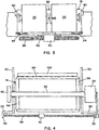
- a printer 10 includes a housing 12 enclosing a drum 14 which is supported for rotation in the direction indicated by the arrow 16 and a carriage 18 supporting a spaced pair of ink jet printheads 20 and 22 which are arranged to eject ink drops selectively Onto a substrate sheet 24 carried by the drum 14.
- the drum 14 has an axial drive shaft 26 which is supported at opposite ends in bearings 28 in two support plates 30 which are rigidly supported on a base plate 32.
- a drive motor 34 is coupled to one end of the drum drive shaft 26 and also to a lead screw 36 which is supported at opposite ends in bearings 38 supported by brackets 39 (Fig. 4) (from the support plates 30.
- both the drum drive shaft 26 and the lead screw 36 are biased toward the right end of the support plate 30, as seen in Fig. 2, by spring washers (not shown.)
- the lead screw 36 passes through a nut 40 affixed to the carriage 18 supporting the printheads 20 and 22 and the pitch of the lead screw 36 is selected so as to drive the carriage parallel to the drum axis by a predetermined distance during each rotation of the drum 14.
- the lead screw 36 is a KERK rolled lead screw designed for high accuracy of the thread pitch throughout its length and has a high stiffness and the nut 40 is a KERK ZBX plastic antibacklash nut.
- the drive shaft 26 is coupled to an encoder 42 which encodes each position on the drum and thus generates a train of electrical pulses at a rate which is dependent on the rate of rotation of the drum 14, such as 1000 pulses per drum rotation.
- the encoder signals are supplied to a multiplier unit 43, which preferably includes a phase-locked loop (PLL) multiplier and generates ink drop ejection actuation signals for the printheads 20 and 22 at an increased rate which is directly related to the encoder output signals and therefore to the speed of rotation of the drum 14, for example, 13,000 pulses per drum rotation and supplies them to a control unit 44 though a line 46.
- PLL phase-locked loop
- the necessary pulse rate for high resolution images is obtained without requiring a high resolution encoder, which is an order of magnitude more expensive than an encoder, such as a Hewlett-Packard HEDS 5540 encoder, producing 1000 pulses per revolution.
- Both the low resolution encoder 42 and the PLL multiplier unit 43 together cost only a small fraction of the cost of a high resolution encoder producing, for example, 13,000 pulses per revolution.
- the encoder may also be used to control the drum speed during acceleration and deceleration as well as during continuous running when the output is supplied directly through a line 47 to the servocontroller (not shown) in the control unit 44 for the drum drive motor 34, while the PLL multiplier 43 supplies high frequency pulses to control the drop ejection rate.
- a cumulative DC pitch error may occur in the manufacture of a lead screw in the manner shown in Fig. 5. This may amount to about one part in 500, i.e., about one millimeter over the length of a drum 50 cm long. For adjacent image segments produced by 40-orifice arrays which are about 1.7 mm, long the positioning error between adjacent drops resulting from DC pitch error is only about 0.003 mm, which is not visually detectable.
- a cyclical or AC lead pitch error i.e., one which occurs cyclically during each revolution of the lead screw, although very small, may seriously affect image quality.
- This type of error is shown in Fig. 6, which indicates a typical error of 0.02 mm peak-to-peak in pitch variation during each rotation of the screw thread which advances the printhead by 1.27 mm.
- the lead screw must be at the same angular position for each drum angle position during every drum rotation. In other words, the lead screw must rotate at the same rate or an integral multiple of the drum rotation but may not rotate at a lower rate.
- Each of the printheads 20 and 22 has the same structure, which is illustrated schematically in Fig. 7 for the printhead 20.
- the printhead 20 has four ink reservoirs 48, 50, 52 and 54.
- Each reservoir supplies a different ink for selective ejection from a corresponding array of 40 orifices in an orifice plate 56 which is mounted at the side of the printhead facing the substrate sheet 24. Since there are 40 orifices in the array supplied by each reservoir, the orifice plate 56 contains a total of 160 orifices 58 in a straight line.
- the printhead 20 includes a conventional piezoelectric drop ejection arrangement for each of the orifices 58 whereby ink supplied from a corresponding reservoir is selectively ejected through the orifice as a drop at the appropriate time in response to a signal received through a line 60 from the control unit 44.
- each of the ink reservoirs 48-54 in the printhead 20 is replenished periodically though a corresponding conduit in a flexible ink supply line 62 from one of series of corresponding remote stationary reservoirs 64, 66, 68 and 70 provided in the housing 10.
- a similar set of stationary reservoirs 72, 74, 76 and 78 is also connected through conduits in a supply line 63 to corresponding reservoirs in the printhead 22 and that printhead likewise receives signals from the line 60 to control the ejection of ink drops from the orifices therein.
- the stationary reservoirs 64-78 are readily accessible to the operator of the system to permit replenishment of the ink as needed.
- the supply lines 62 and 63 may also include a vacuum conduit by which subatomospheric pressure may be supplied to the printheads 20 and 22 for deaeration of the ink as described, for example, in the Hine et. al. Patent No. 4,940,995, the disclosure of which is incorporated herein by reference.
- each ink conduit in the lines 62 and 63 may include a heater wire in order to melt the ink in the conduit during refill of a printhead reservoir from the corresponding stationary reservoir as described, for example, in the Hoisington et. al. Patent No. 4,814,786.
- digital signals representing the image information in terms of color and density of each pixel are supplied through an input line 82 to the control unit 44.
- the control unit converts these signals in a conventional manner to produce selective ink drop ejection actuation signals timed for operation of the piezoelectric actuators in the ink jet heads 20 and 22 at the appropriate times to eject ink drops of appropriate color and density for deposition at predetermined locations on the substrate sheet 24 as the drum 14 is rotated and the printheads 20 and 22 are advanced parallel to the axis of the drum by rotation of the lead screw 36.
- This low density ink may then be used to produce further reduced density images by printing fewer drops, as with the high density ink. Because the ink is low density, it may be possible to get past the minimum point on the Banderly curve without a grainy image. If not, a third, even less dense, ink may be employed, and if this produces a grainy image at same spot separation, then a fourth, lower density ink could be employed.
- the stationary reservoirs 64, 66, 68 and 70 connected to the printhead 20 contain conventional, high-density black, magenta, cyan and yellow inks, respectively, which are, in turn, supplied to the onhead reservoirs, 48, 50, 52 and 54 in the printhead 20 for selective ejection from corresponding groups of 40 orifices 58 in the orifice plate 56 during the printing operation and three of the four stationary reservoirs 72, 74, 76 and 78 connected to the printhead 22 are supplied with low-density black, magenta and cyan inks, respectively.
- the invention takes advantage of the fact that the visual perception of density gradations of yellow ink is substantially less than that of cyan, magenta and black inks in order to enhance the quality of a color image without increasing the total number of inks required or the complexity of the printing system.
- the fourth reservoir connected to the printhead 22, instead of providing low density yellow ink is utilized for a special color, such as red or green, which might otherwise require a combination of the standard subtractive colors, or a specific hue which may be used frequently in the printing operation.
- the fourth reservoir of that set may be supplied with black ink of even lower density than the black ink in the other reservoir in order to enhance the range of available densities.
- the four reservoirs connected to the printhead 20 supply yellow ink and black inks of three different density levels and the four reservoirs connected to the printhead 22 supply cyan and magenta inks at two different density levels. This reduces the drop positioning errors in placing high and low density inks of the same color adjacent to each other.
- each ink drop applied to the substrate 24 must be deposited at precisely the required position and, to accomplish this, any error in the location of the printhead orifices with respect to the required position must be kept below about 0.005mm.
- the printhead 22 must be positioned on the carriage so as to apply ink drops to exactly the same locations on the substrate sheet 24 as those to which drops may be applied from the printhead 20, either in combination with drops from the printhead 20 or in place of drops from printhead 20 depending upon the selective activation signals supplied through the line 60 from the control unit 49.
- the carriage 18 includes, as schematically illustrated in Fig. 3, an angular printhead adjustment 84 for adjusting the sabre angle of each of the printheads 20 and 22 and a lateral spacing adjustment 86 to adjust the axial spacing of the heads with respect to each other.
- the sabre angle is zero and the spacing between the last of the orifices 58 in the printhead 20 and the first of the orifices 58 in the printhead 22 is set at 64 image pixels. If a sabre angle other than zero is used, the control unit 44 should be programmed to time the drop ejection pulses to compensate for differing drop path lengths due to the curvature of the drum surface, taking the substrate motion into account.
- the printheads 20 and 22 may be spaced in the circumferential direction of the drum rather than in the axial direction as shown schematically in Fig 8.
- the physical spacing between orifices in axially spaced printheads must be precisely equal to a unit number of image pixels, the spacing between orifices in angularly spaced printheads need not be equal to a unit number of pixels.
- timing of the pulses from the control unit 44 may be used to compensate for variations in the relative positions of the orifices in the printheads 20 and 22 in the circumferential direction of the drum, regardless of whether the printheads are spaced axially or circumferentially.
- the carriage 18 is supported on a rail 88 which is affixed near opposite ends on the support plates 30 so as to provide a predetermined spacing between the rail 88 and the drum drive shaft bearings 28 in the support plates 30.
- the carriage 18 is slidably supported on the carriage support rail 88 by three bearing pads 90 which engage the carriage support rail surfaces and have dimensions which provide predetermined, precisely controlled spacing between the rail 88 and the orifice plate 56 in each of the printheads 20 and 22, the rail surfaces being spaced at a distance from the drum axis which is kept to within about 0.025 mm of the desired value.
- the support plates 30 are welded to a torsionally stiff, rectangular steel tube 92 about three millimeters thick and having cross-sectional dimensions of about 3.75cm by 7.75cm.
- the drum 14 consists of an aluminum cylinder 94 supported at opposite ends from the drive shaft 26 by thermally insula-tive glass-reinforced plastic end bells 96.
- the outer drum surface is machined by drum rotation to provide the desired drum diameter, which in a preferred embodiment is approximately 16.4 cm, and to assure uniform spacing of the surface 98 of the drum from the axis of the drive shaft 26.
- This machining of the assembled drum minimizes runout of the drum surface 98 to 0.1mm, which is small enough to prevent visual detection of image errors resulting from drum surface runout.
- the spacing between the orifice plates 56 of the printheads mounted on the carriage 18 and the surface of the drum 14 can be maintained within about 0.075mm.
- a drum heater 100 is mounted outside the drum closely adjacent to the drum surface 98 and is controlled by a temperature detector 102 which engages the surface 98 of the drum outside the image area.
- the thickness of the aluminum cylinder 94 is preferably in the range of about 0.25 to 1.25 cm.
- the housing 12 is provided with an internal partition 104, containing entrance and exit openings for the sheets 24, which defines a "hot zone" enclosing most of the printer components other than the control unit 44 and the power supply.
- a thermostatically controlled exhaust fan 106 responsive to a temperature detector 108 mounted on one of the support plates 30, which is representative of the ambient temperature within the hot zone, is arranged to exhaust air from the hot zone whenever the detected temperature exceeds a predetermined value.
- the drum heater 100 has a circumferential dimension equal to about 30-45% of the drum circumference and an axial length approximately equal to that of the drum and the radial spacing of the heater from the drum is about 1-2mm.
- the hot zone within the housing 12 is maintained at a temperature no less than about 10°C below of the desired temperature of the surface 98, for example at about 35°-45°C.
- a supply of substrate material much as sheets of paper 24 is maintained in a supply tray 110 which is received in the lower end of the rear wall of the housing 12.
- Each sheet 24 is selectively removed from the tray 110 as needed by a friction feed device 112 which advances the top sheet from the supply tray through an opening near the bottom of the partition 104 to a pair of feed rolls 114.
- the sheet 24 With the drum 14 in a stationary position, the sheet 24 is fed against the inclined surface of a baffle 116 which directs the sheet against the drum surface until it is received within a set of lead edge grippers 118 which are actuated in a conventional manner by internal cams (not shown) within the drum 14 so as to be raised away from the drum surface until the sheet 24 is properly positioned.
- the grippers 118 are closed to clamp the lead edge of the sheet to the drum surface and the drum is rotated in the direction indicated by the arrow 16 and the sheet is held tightly against the drum by a roll 119 until a set of tail edge grippers 120 is in position to receive and clamp the trailing edge of the sheet 24 against the drum surface.
- the sheet In order to assure good image quality the sheet must be held in intimate contact with the drum surface while the image is printed.
- the lead edge grippers 118 are raised to release the lead edge of the sheet and a set of stripper rolls 121 and sheet strippers 122, shown in Fig. 1, are moved against the drum surface to strip the sheet 24 from the drum and direct it through an opening 123 near the top of the partition 104.
- the stripper rolls 121 which have a diameter of about 2.5 cm. and are urged with a low force of about 180 gm ⁇ cm of roll width, are made of resilient rubber or similar material having a low modulus i.e. a durometer of less than about 35 and preferably less than 25, covered by a sleeve of inert material such as polytetrafluoroethylene.
- the combination of large roll diameter, low modulus, and low substrate engaging force prevents marring of the ink images on the substrate.
- a pair of outfeed drive rolls 124 receive the sheet outside the opening 123 in the partition 104 and convey it to an output tray 126, the trailing edge of the sheet 24 being released by the grippers 120 after the sheet has been captured by the outfeed rolls 124. Since the outfeed rolls 124 are located outside the hot zone, the image on the sheet 24 has cooled sufficiently by the time it reaches them to prevent any disturbance of the image as it passes between them.
- the carriage 18 On startup and periodically during operation of the printer, for example after every 20 or 30 prints have been made, the carriage 18 is automatically driven to the left end of the support rail 88 as seen Fig. 2, where the print-heads 20 and 22 are positioned adjacent to a maintenance station 128.
- the orifice plates 56 are cleaned by wiping with a web of paper as described, for example, in the Spehrley, Jr. et. al. Patent No. 4,928,210, the disclosure of which is incorporated herein by reference.
- any necessary purging of the print-heads is carried out at the maintenance station in the manner described in that patent and in the Hine et. al. Patent No. 4,937,598, the disclosure of which is also incorporated herein by reference.
- the supply lines 62 and 63 may also include an air pressure conduit supplying air at elevated pressure to each printhead.
- the control unit 44 transmits signals to the printheads which cause them to print images using an interlace technique.
- interlace arrangement ink is ejected during each drum rotation from orifices 58 in each bead which are spaced from each other rather than from adjacent orifices.
- Typical ink jet interlace techniques are described, for example, in the Hoisington et. al. Patent No. 5,075,689, the disclosure of which is incorporated herein by reference.
- the orifices which eject ink drops orifice in each color array in the printheads 20 and 22 during any scan are spaced by approximately 0.47mm.
- this may be accomplished in many ways.
- the orifices which are actuated during any given scan of a 40-orifice array may be spaced by eleven image pixels, which provides a resolution in the subscanning axial direction i.e., the direction parallel to the drum axis, of 232.3 dots/cm., or, for an array having 35 to 39 orifices, by thirteen image pixels which provides resolution in that direction of 274.4 dots/cm.
- the spacing between orifices activated during any scan may be twelve image pixels, providing resolution of 253.5 dots/cm. and for a 39-orifice array, the orifices actuated during any scan may be spaced by fourteen image pixels, which provides subscanning direction resolution of 295.7 dots/cm. Certain of these arrangements may be more effective than others in avoiding visual effects of drop positioning errors.
- the encoder 42 In a typical printer arranged according to the invention, in which the encoder 42 generates 1000 pulses per drum rotation and the control unit produces selective actuation pulses at a rate of 13,000 per drum rotation, and in which the drum diameter is 16.4 cm., the resolution is the circumferential direction of the drum is 252.6 dots/cm. With that drum diameter, a substrate sheet having dimensions of about 35.5 cm. by 50 cm. can be accommodated and high-resolution multicolor continuous images about having a size as large as 35 cm. by 49 cm. can be printed. With a drum speed of about 60 rpm, the images can be printed at a rate of about ten per hour.
- the resulting image will have a trapezoidal shape which is very slightly skewed from rectangular, by 1.7 mm in a height of 355 mm, which is not easily noticed. If desired, this can be corrected by appropriate programming of the control unit 44 to preconfigure the image by the same skewed amount in the opposite direction.
- the carriage 18 may be indexed intermittently rather than continuously by a servomotor, which replaces the coupling between the lead screw and the drumdrive motor 34.
- the servomotor is actuated to advance the printhead by a distance in pixels corresponding to the number of orifices in each color array by turning the lead screw preferably one revolution during the interval between the tail edge and the lead edge of the sheet 24 as the drum 14 rotates.
- the servometer can be controlled during printing directly from the encoder output through the line 47 and the carriage 18 can be returned at high speed after completing the printing of an image while the drum is stationary or turning at a low speed to permit loading and loading of the sheets 24 on the drums.
Landscapes
- Engineering & Computer Science (AREA)
- Quality & Reliability (AREA)
- Ink Jet (AREA)
- Particle Formation And Scattering Control In Inkjet Printers (AREA)
Applications Claiming Priority (3)
| Application Number | Priority Date | Filing Date | Title |
|---|---|---|---|
| US432783 | 1995-05-02 | ||
| US08/432,783 US7237872B1 (en) | 1995-05-02 | 1995-05-02 | High resolution multicolor ink jet printer |
| EP96913907A EP0771274A4 (de) | 1995-05-02 | 1996-05-02 | Hochauflösende mehrfarbentintenstrahlvorrichtung |
Related Parent Applications (1)
| Application Number | Title | Priority Date | Filing Date |
|---|---|---|---|
| EP96913907.0 Division | 1996-11-07 |
Publications (2)
| Publication Number | Publication Date |
|---|---|
| EP0949081A1 true EP0949081A1 (de) | 1999-10-13 |
| EP0949081B1 EP0949081B1 (de) | 2002-08-14 |
Family
ID=23717571
Family Applications (2)
| Application Number | Title | Priority Date | Filing Date |
|---|---|---|---|
| EP96913907A Withdrawn EP0771274A4 (de) | 1995-05-02 | 1996-05-02 | Hochauflösende mehrfarbentintenstrahlvorrichtung |
| EP99202139A Expired - Lifetime EP0949081B1 (de) | 1995-05-02 | 1996-05-02 | Hochauflösender Mehrfarbentintenstrahldrucker |
Family Applications Before (1)
| Application Number | Title | Priority Date | Filing Date |
|---|---|---|---|
| EP96913907A Withdrawn EP0771274A4 (de) | 1995-05-02 | 1996-05-02 | Hochauflösende mehrfarbentintenstrahlvorrichtung |
Country Status (5)
| Country | Link |
|---|---|
| US (2) | US7237872B1 (de) |
| EP (2) | EP0771274A4 (de) |
| JP (1) | JP3256546B2 (de) |
| DE (1) | DE69623058T2 (de) |
| WO (1) | WO1996034762A1 (de) |
Cited By (4)
| Publication number | Priority date | Publication date | Assignee | Title |
|---|---|---|---|---|
| GB2379414A (en) * | 2001-09-10 | 2003-03-12 | Seiko Epson Corp | Method of forming a large flexible electronic display on a substrate using an inkjet head(s) disposed about a vacuum roller holding the substrate |
| US6811641B2 (en) * | 2001-12-12 | 2004-11-02 | Eastman Kodak Company | Lamination method to create a pre-press proof with a thermal mark |
| US7021735B2 (en) | 2003-03-28 | 2006-04-04 | Lexmark International, Inc. | Reduction of color plane alignment error in a drum printer |
| US8441474B2 (en) | 2008-06-25 | 2013-05-14 | Aristocrat Technologies Australia Pty Limited | Method and system for setting display resolution |
Families Citing this family (17)
| Publication number | Priority date | Publication date | Assignee | Title |
|---|---|---|---|---|
| US7237872B1 (en) * | 1995-05-02 | 2007-07-03 | Fujifilm Dimatrix, Inc. | High resolution multicolor ink jet printer |
| EP0897806B1 (de) * | 1996-12-18 | 2003-03-26 | Toshiba Tec Kabushiki Kaisha | Tintenstrahldrucker |
| EP1003083B1 (de) | 1998-11-16 | 2001-04-11 | Agfa-Gevaert N.V. | Grossformatdrucker mit einer zentralen Konditioniereinheit zur Kontrolle und Überwachung des Entwicklerzustandes |
| EP1041816B1 (de) * | 1999-03-31 | 2004-05-26 | Agfa-Gevaert | Verbesserter Farbqualitätsdruck, der mehrere Druckstationen für dieselbe Farbe benutzt |
| EP1433308A2 (de) * | 2001-10-04 | 2004-06-30 | E.I. Du Pont De Nemours And Company | Tintenstrahldruck |
| US7627343B2 (en) * | 2003-04-25 | 2009-12-01 | Apple Inc. | Media player system |
| US8001924B2 (en) | 2006-03-31 | 2011-08-23 | Asml Netherlands B.V. | Imprint lithography |
| US8186790B2 (en) * | 2008-03-14 | 2012-05-29 | Purdue Research Foundation | Method for producing ultra-small drops |
| US8553281B2 (en) * | 2008-12-05 | 2013-10-08 | Alpha Technologies Inc. | High density, high intensity ink formulation and method for printing high intensity colors |
| US20100259589A1 (en) * | 2009-04-14 | 2010-10-14 | Jonathan Barry | Inert uv inkjet printing |
| US8567936B2 (en) * | 2010-11-10 | 2013-10-29 | Electronics For Imaging, Inc. | LED roll to roll drum printer systems, structures and methods |
| US8317298B2 (en) | 2010-11-18 | 2012-11-27 | Xerox Corporation | Inkjet ejector arrays aligned to a curved image receiving surface with ink recirculation |
| JP5605199B2 (ja) * | 2010-12-10 | 2014-10-15 | コニカミノルタ株式会社 | インクジェット記録装置及びインクジェット記録方法 |
| JP5673055B2 (ja) * | 2010-12-10 | 2015-02-18 | コニカミノルタ株式会社 | インクジェット記録装置 |
| JP5761202B2 (ja) * | 2010-12-10 | 2015-08-12 | コニカミノルタ株式会社 | インクジェット記録装置 |
| US9527307B2 (en) | 2010-12-15 | 2016-12-27 | Electronics For Imaging, Inc. | Oxygen inhibition for print-head reliability |
| US9487010B2 (en) | 2010-12-15 | 2016-11-08 | Electronics For Imaging, Inc. | InkJet printer with controlled oxygen levels |
Citations (13)
| Publication number | Priority date | Publication date | Assignee | Title |
|---|---|---|---|---|
| US4538160A (en) * | 1982-01-26 | 1985-08-27 | Minolta Camera Kabushiki Kaisha | Ink jet recording apparatus |
| US4672432A (en) | 1983-04-28 | 1987-06-09 | Canon Kabushiki Kaisha | Method for recording a color image using dots of colorants of different densities |
| US4686538A (en) | 1984-10-31 | 1987-08-11 | Canon Kabushiki Kaisha | Tone recording method |
| US4692773A (en) | 1982-07-23 | 1987-09-08 | Canon Kabushiki Kaisha | Image forming method using image forming elements having different concentrations and pitches |
| US4814786A (en) | 1987-04-28 | 1989-03-21 | Spectra, Inc. | Hot melt ink supply system |
| WO1989012215A1 (en) * | 1988-06-03 | 1989-12-14 | Spectra, Inc. | Controlled ink drop spreading in hot melt ink jet printing |
| JPH0247075A (ja) * | 1988-08-08 | 1990-02-16 | Minolta Camera Co Ltd | 記録装置 |
| US4937598A (en) | 1989-03-06 | 1990-06-26 | Spectra, Inc. | Ink supply system for an ink jet head |
| US4940995A (en) | 1988-11-18 | 1990-07-10 | Spectra, Inc. | Removal of dissolved gas from ink in an ink jet system |
| DE4021227A1 (de) * | 1990-07-04 | 1991-06-06 | Siemens Ag | Vorrichtung zum trocknen von aufzeichnungstraegern in tintendruckeinrichtungen |
| US5075689A (en) | 1989-05-31 | 1991-12-24 | Spectra, Inc. | Bidirectional hot melt ink jet printing |
| EP0568272A1 (de) * | 1992-05-01 | 1993-11-03 | Hewlett-Packard Company | Vorheizwalze für einen thermischen Tintenstrahldrucker |
| EP0610096A2 (de) * | 1993-02-05 | 1994-08-10 | Canon Kabushiki Kaisha | Farbstrahlaufzeichnungsgerät |
Family Cites Families (70)
| Publication number | Priority date | Publication date | Assignee | Title |
|---|---|---|---|---|
| US3008372A (en) | 1958-05-26 | 1961-11-14 | Servo Corp Of America | Code-wheel manufacturing apparatus |
| US3438057A (en) | 1966-12-30 | 1969-04-08 | Texas Instruments Inc | Photographic recorder using an array of solid state light emitters |
| GB1201624A (en) | 1967-11-14 | 1970-08-12 | Monotype Corp Ltd | Improvements in or relating to display apparatus |
| US3512158A (en) | 1968-05-02 | 1970-05-12 | Bunker Ramo | Infra-red printer |
| US3952311A (en) | 1972-04-24 | 1976-04-20 | The Laitram Corporation | Electro-optical printing system |
| US4009332A (en) | 1976-06-28 | 1977-02-22 | International Business Machines Corporation | Memory management system for an ink jet copier |
| DE2928746A1 (de) | 1979-07-17 | 1981-02-05 | Bayer Ag | Verfahren zur herstellung von pyridin-4-aldehyd-phenylhydrazonen |
| JPS5644259A (en) | 1979-09-20 | 1981-04-23 | Canon Inc | Copying and recording device |
| JPS57178783A (en) | 1981-04-28 | 1982-11-04 | Canon Inc | Recorder |
| DE3122645A1 (de) | 1981-06-06 | 1982-12-23 | Olympia Werke Ag, 2940 Wilhelmshaven | Horizontalantrieb fuer einen aufzeichnungskopf |
| US4401991A (en) | 1981-10-08 | 1983-08-30 | International Business Machines Corporation | Variable resolution, single array, interlace ink jet printer |
| JPS5872461A (ja) | 1981-10-26 | 1983-04-30 | Fujitsu Ltd | インクジエツト記録装置 |
| JPS5970582A (ja) | 1982-10-15 | 1984-04-21 | Toray Ind Inc | 円筒走査型インクジエツトプリンタ |
| JPS5970583A (ja) * | 1982-10-15 | 1984-04-21 | Toray Ind Inc | インクジエツトプリンタのヘツド移動方法 |
| DE3300447A1 (de) | 1983-01-08 | 1984-07-12 | Philips Patentverwaltung Gmbh, 2000 Hamburg | Rotations-aufzeichnungsverfahren |
| US4525428A (en) * | 1983-01-25 | 1985-06-25 | Mitsubishi Paper Mills, Ltd. | Process for producing multicolor heat-transfer recording paper |
| GB2139450B (en) | 1983-03-08 | 1987-12-16 | Canon Kk | Color picture forming apparatus |
| JPS59215889A (ja) * | 1983-05-24 | 1984-12-05 | Canon Inc | インクジエツト記録方法 |
| US4574291A (en) * | 1984-08-29 | 1986-03-04 | Tektronix, Inc. | Phase locked synchronizer for printer timing control |
| JPS6183046A (ja) * | 1984-09-29 | 1986-04-26 | Minolta Camera Co Ltd | 階調表現可能なインクジエツト記録装置 |
| JPS61108255A (ja) | 1984-10-31 | 1986-05-26 | Canon Inc | 階調記録方法 |
| US4880324A (en) * | 1985-06-24 | 1989-11-14 | Canon Kabushiki Kaisha | Transfer method for heat-sensitive transfer recording |
| JPS62180839A (ja) | 1986-01-31 | 1987-08-08 | Ricoh Co Ltd | ドラム給紙装置 |
| JPS6321167A (ja) | 1986-07-15 | 1988-01-28 | Ricoh Co Ltd | 回転ドラム方式インクジエツト記録装置 |
| JPS63183866A (ja) | 1986-08-07 | 1988-07-29 | Nippon Seimitsu Kogyo Kk | 印刷装置 |
| JPS63205241A (ja) | 1987-02-20 | 1988-08-24 | Fujitsu Ltd | 定着機構付ホツトメルトインクジエツト記録装置 |
| US5140339A (en) | 1987-03-23 | 1992-08-18 | Canon Kabushiki Kaisha | Ink jet recording with equal amounts of mono- and mixed color droplets |
| JP2749814B2 (ja) | 1987-03-23 | 1998-05-13 | キヤノン株式会社 | インクジエツト記録方法 |
| JPS63288769A (ja) | 1987-05-21 | 1988-11-25 | Nec Corp | スペ−シング機構 |
| US4860026A (en) | 1987-06-25 | 1989-08-22 | Canon Kabushiki Kaisha | Halftone image recording method using recording data having a plurality of concentrations for one color |
| JP2640347B2 (ja) | 1987-08-26 | 1997-08-13 | キヤノン株式会社 | インクジェット記録装置 |
| US5337079A (en) | 1987-09-09 | 1994-08-09 | Spectra, Inc. | Post-processing of colored hot melt ink images |
| US4873134A (en) | 1988-08-10 | 1989-10-10 | Spectra, Inc. | Hot melt ink projection transparency |
| US5023111A (en) | 1988-08-10 | 1991-06-11 | Spectra, Inc. | Treatment of hot melt ink images |
| US4751528A (en) | 1987-09-09 | 1988-06-14 | Spectra, Inc. | Platen arrangement for hot melt ink jet apparatus |
| JPH01228859A (ja) | 1988-03-09 | 1989-09-12 | Toshiba Corp | インクジェット式記録装置 |
| JP2717798B2 (ja) | 1988-05-13 | 1998-02-25 | キヤノン株式会社 | インクジェット記録方法 |
| US4971408A (en) | 1988-11-15 | 1990-11-20 | Spectra, Inc. | Remelting of printed hot melt ink images |
| US5105204A (en) | 1988-06-03 | 1992-04-14 | Spectra, Inc. | Subtractive color hot melt ink reflection images on opaque substrates |
| US5114747A (en) | 1988-08-10 | 1992-05-19 | Spectra, Inc. | Treatment of hot melt ink images |
| JP2791066B2 (ja) * | 1988-11-15 | 1998-08-27 | キヤノン株式会社 | 記録装置 |
| JP3133750B2 (ja) | 1989-03-24 | 2001-02-13 | キヤノン株式会社 | インクジェットカートリッジおよびそれを用いるインクジェット記録装置 |
| JPH02286250A (ja) | 1989-04-26 | 1990-11-26 | Seiko Epson Corp | インクジェットプリンタ |
| JP2859296B2 (ja) * | 1989-06-01 | 1999-02-17 | キヤノン株式会社 | 画像再生方法及びその装置 |
| JP2772362B2 (ja) | 1989-07-25 | 1998-07-02 | オルガノ株式会社 | 液体中の溶存炭酸ガス除去装置 |
| US4920355A (en) * | 1989-07-31 | 1990-04-24 | Eastman Kodak Company | Interlace method for scanning print head systems |
| US4978971A (en) | 1989-11-06 | 1990-12-18 | Tektronix, Inc. | Method and apparatus for reformatting print data |
| JPH03288674A (ja) | 1990-04-05 | 1991-12-18 | Canon Inc | 記録装置 |
| JPH04140148A (ja) | 1990-10-01 | 1992-05-14 | Canon Inc | インクジェット記録方法 |
| JP2608806B2 (ja) | 1990-11-29 | 1997-05-14 | シルバー精工株式会社 | インクジェットプリンタにおけるレジストレーション調整装置 |
| JP2704339B2 (ja) | 1991-02-01 | 1998-01-26 | テクトロニクス・インコーポレイテッド | インタレース印刷方法 |
| JPH0516367A (ja) | 1991-07-09 | 1993-01-26 | Canon Inc | 画像記録装置 |
| DE69209438T2 (de) | 1991-11-04 | 1996-10-31 | Hewlett Packard Co | Grossbereich-Drucker/Schreiber mit mehreren Schreibkassetten |
| US5402156A (en) | 1992-06-29 | 1995-03-28 | Xerox Corporation | Slow scan stitching mechanism |
| JP3313777B2 (ja) | 1992-09-24 | 2002-08-12 | キヤノン株式会社 | 記録装置および記録方法 |
| JPH06115079A (ja) | 1992-10-06 | 1994-04-26 | Canon Inc | 記録装置 |
| US5372852A (en) * | 1992-11-25 | 1994-12-13 | Tektronix, Inc. | Indirect printing process for applying selective phase change ink compositions to substrates |
| JP2500583B2 (ja) | 1993-03-17 | 1996-05-29 | 日本電気株式会社 | 画像信号の量子化特性制御方法及び画像信号圧縮符号化装置 |
| US5825377A (en) | 1993-04-28 | 1998-10-20 | Canon Kabushiki Kaisha | Method and apparatus for ink-jet recording with inks having different densities |
| JP3236120B2 (ja) | 1993-04-28 | 2001-12-10 | キヤノン株式会社 | インクジェット記録装置およびインクジェット記録方法 |
| JP3227268B2 (ja) * | 1993-05-26 | 2001-11-12 | キヤノン株式会社 | インクジェット記録装置およびインクジェット記録方法 |
| US5485183A (en) * | 1993-06-30 | 1996-01-16 | Dataproducts Corporation | Interlaced dot-on-dot printing |
| US5568173A (en) * | 1993-09-07 | 1996-10-22 | Agfa-Gevaert, N.V. | Ink jet printing method |
| JP3218851B2 (ja) | 1994-03-29 | 2001-10-15 | ミノルタ株式会社 | 電気−機械変換素子を使用した駆動装置の駆動方法 |
| US5574078A (en) * | 1994-11-10 | 1996-11-12 | Lasermaster Corporation | Thermal compositions |
| US5625397A (en) * | 1994-11-23 | 1997-04-29 | Iris Graphics, Inc. | Dot on dot ink jet printing using inks of differing densities |
| US7237872B1 (en) | 1995-05-02 | 2007-07-03 | Fujifilm Dimatrix, Inc. | High resolution multicolor ink jet printer |
| JP3288674B2 (ja) | 1999-05-10 | 2002-06-04 | 佐伯 芳子 | 低水分含量で高カロリーの栄養バランスに優れた加工食品 |
| JP4140148B2 (ja) | 1999-11-04 | 2008-08-27 | 株式会社三洋物産 | 電動式パチンコ機の操作ハンドル |
| JP4201263B2 (ja) | 2003-10-27 | 2008-12-24 | 日本電信電話株式会社 | 侵入検知システムおよび記録媒体 |
-
1995
- 1995-05-02 US US08/432,783 patent/US7237872B1/en not_active Expired - Lifetime
-
1996
- 1996-05-02 EP EP96913907A patent/EP0771274A4/de not_active Withdrawn
- 1996-05-02 JP JP53350296A patent/JP3256546B2/ja not_active Expired - Lifetime
- 1996-05-02 DE DE69623058T patent/DE69623058T2/de not_active Expired - Lifetime
- 1996-05-02 WO PCT/US1996/006175 patent/WO1996034762A1/en not_active Ceased
- 1996-05-02 EP EP99202139A patent/EP0949081B1/de not_active Expired - Lifetime
-
2007
- 2007-06-20 US US11/765,890 patent/US7690779B2/en not_active Expired - Fee Related
Patent Citations (13)
| Publication number | Priority date | Publication date | Assignee | Title |
|---|---|---|---|---|
| US4538160A (en) * | 1982-01-26 | 1985-08-27 | Minolta Camera Kabushiki Kaisha | Ink jet recording apparatus |
| US4692773A (en) | 1982-07-23 | 1987-09-08 | Canon Kabushiki Kaisha | Image forming method using image forming elements having different concentrations and pitches |
| US4672432A (en) | 1983-04-28 | 1987-06-09 | Canon Kabushiki Kaisha | Method for recording a color image using dots of colorants of different densities |
| US4686538A (en) | 1984-10-31 | 1987-08-11 | Canon Kabushiki Kaisha | Tone recording method |
| US4814786A (en) | 1987-04-28 | 1989-03-21 | Spectra, Inc. | Hot melt ink supply system |
| WO1989012215A1 (en) * | 1988-06-03 | 1989-12-14 | Spectra, Inc. | Controlled ink drop spreading in hot melt ink jet printing |
| JPH0247075A (ja) * | 1988-08-08 | 1990-02-16 | Minolta Camera Co Ltd | 記録装置 |
| US4940995A (en) | 1988-11-18 | 1990-07-10 | Spectra, Inc. | Removal of dissolved gas from ink in an ink jet system |
| US4937598A (en) | 1989-03-06 | 1990-06-26 | Spectra, Inc. | Ink supply system for an ink jet head |
| US5075689A (en) | 1989-05-31 | 1991-12-24 | Spectra, Inc. | Bidirectional hot melt ink jet printing |
| DE4021227A1 (de) * | 1990-07-04 | 1991-06-06 | Siemens Ag | Vorrichtung zum trocknen von aufzeichnungstraegern in tintendruckeinrichtungen |
| EP0568272A1 (de) * | 1992-05-01 | 1993-11-03 | Hewlett-Packard Company | Vorheizwalze für einen thermischen Tintenstrahldrucker |
| EP0610096A2 (de) * | 1993-02-05 | 1994-08-10 | Canon Kabushiki Kaisha | Farbstrahlaufzeichnungsgerät |
Non-Patent Citations (1)
| Title |
|---|
| PATENT ABSTRACTS OF JAPAN vol. 014, no. 209 (M - 0968) 27 April 1990 (1990-04-27) * |
Cited By (5)
| Publication number | Priority date | Publication date | Assignee | Title |
|---|---|---|---|---|
| GB2379414A (en) * | 2001-09-10 | 2003-03-12 | Seiko Epson Corp | Method of forming a large flexible electronic display on a substrate using an inkjet head(s) disposed about a vacuum roller holding the substrate |
| US7108369B2 (en) | 2001-09-10 | 2006-09-19 | Seiko Epson Corporation | Inkjet deposition apparatus and method |
| US6811641B2 (en) * | 2001-12-12 | 2004-11-02 | Eastman Kodak Company | Lamination method to create a pre-press proof with a thermal mark |
| US7021735B2 (en) | 2003-03-28 | 2006-04-04 | Lexmark International, Inc. | Reduction of color plane alignment error in a drum printer |
| US8441474B2 (en) | 2008-06-25 | 2013-05-14 | Aristocrat Technologies Australia Pty Limited | Method and system for setting display resolution |
Also Published As
| Publication number | Publication date |
|---|---|
| US20080018682A1 (en) | 2008-01-24 |
| EP0949081B1 (de) | 2002-08-14 |
| JPH09507806A (ja) | 1997-08-12 |
| US7690779B2 (en) | 2010-04-06 |
| US7237872B1 (en) | 2007-07-03 |
| EP0771274A1 (de) | 1997-05-07 |
| JP3256546B2 (ja) | 2002-02-12 |
| DE69623058T2 (de) | 2002-12-05 |
| WO1996034762A1 (en) | 1996-11-07 |
| EP0771274A4 (de) | 1998-02-11 |
| DE69623058D1 (de) | 2002-09-19 |
Similar Documents
| Publication | Publication Date | Title |
|---|---|---|
| US7690779B2 (en) | High resolution multicolor ink jet printer | |
| EP0938973B1 (de) | Apparat und Verfahren zum automatischen Ausrichten von Druckköpfen | |
| US7959259B2 (en) | Inkjet printing apparatus and driving control method | |
| EP0748693B1 (de) | Thermo-Tintenstrahldruckkopf mit ausgedehnter Druckfähigkeit | |
| JP2003211770A (ja) | カラー画像記録装置 | |
| US8562098B2 (en) | Recording apparatus and recording method | |
| US7478893B2 (en) | Liquid ejection control method and liquid ejection apparatus | |
| US8376498B1 (en) | High productivity spreader/transfix system for duplex media sheets in an inkjet printer | |
| US4495507A (en) | Multicolor transfer heat-sensitive recording apparatus | |
| USRE33496E (en) | Thermal transfer recording apparatus | |
| US6332665B1 (en) | Skewed substrate pixel array printing machine | |
| EP0830944B1 (de) | Tintenstrahldruckvorrichtung mit Trommelkopf | |
| EP0881081B1 (de) | Serielles Thermisches Aufzeichnungsgerät | |
| JP2001158135A (ja) | インクジェットプリントヘッドと感熱式レーザプリントヘッドを用いてカラー像を印刷する方法および装置 | |
| JP3040455B2 (ja) | 画像形成装置 | |
| JP2003305830A (ja) | 記録装置および記録方法 | |
| JPH02187355A (ja) | 画像記録装置 | |
| JPH03199052A (ja) | 複写装置 | |
| US4639742A (en) | Method and apparatus for printing an image | |
| KR0132419B1 (ko) | 비디오 프린터 장치 | |
| JPH06344624A (ja) | 記録装置 | |
| JP2004034472A (ja) | インクジェット記録装置 | |
| JPH03189159A (ja) | インクジェット記録装置 | |
| JPH11192734A (ja) | 画像形成装置および画像形成システム | |
| GB2254048A (en) | Thermal printhead with plural lines of printing elements. |
Legal Events
| Date | Code | Title | Description |
|---|---|---|---|
| PUAI | Public reference made under article 153(3) epc to a published international application that has entered the european phase |
Free format text: ORIGINAL CODE: 0009012 |
|
| 17P | Request for examination filed |
Effective date: 19990701 |
|
| AC | Divisional application: reference to earlier application |
Ref document number: 771274 Country of ref document: EP |
|
| AK | Designated contracting states |
Kind code of ref document: A1 Designated state(s): DE FR GB |
|
| AX | Request for extension of the european patent |
Free format text: AL;LT;LV;SI |
|
| AKX | Designation fees paid |
Free format text: DE FR GB |
|
| GRAG | Despatch of communication of intention to grant |
Free format text: ORIGINAL CODE: EPIDOS AGRA |
|
| 17Q | First examination report despatched |
Effective date: 20011017 |
|
| GRAG | Despatch of communication of intention to grant |
Free format text: ORIGINAL CODE: EPIDOS AGRA |
|
| GRAH | Despatch of communication of intention to grant a patent |
Free format text: ORIGINAL CODE: EPIDOS IGRA |
|
| GRAH | Despatch of communication of intention to grant a patent |
Free format text: ORIGINAL CODE: EPIDOS IGRA |
|
| GRAA | (expected) grant |
Free format text: ORIGINAL CODE: 0009210 |
|
| AC | Divisional application: reference to earlier application |
Ref document number: 771274 Country of ref document: EP |
|
| AK | Designated contracting states |
Kind code of ref document: B1 Designated state(s): DE FR GB |
|
| REG | Reference to a national code |
Ref country code: GB Ref legal event code: FG4D |
|
| REF | Corresponds to: |
Ref document number: 69623058 Country of ref document: DE Date of ref document: 20020919 |
|
| ET | Fr: translation filed | ||
| PLBE | No opposition filed within time limit |
Free format text: ORIGINAL CODE: 0009261 |
|
| STAA | Information on the status of an ep patent application or granted ep patent |
Free format text: STATUS: NO OPPOSITION FILED WITHIN TIME LIMIT |
|
| 26N | No opposition filed |
Effective date: 20030515 |
|
| REG | Reference to a national code |
Ref country code: GB Ref legal event code: 732E |
|
| REG | Reference to a national code |
Ref country code: FR Ref legal event code: TP |
|
| REG | Reference to a national code |
Ref country code: FR Ref legal event code: CD Ref country code: FR Ref legal event code: CA |
|
| REG | Reference to a national code |
Ref country code: FR Ref legal event code: PLFP Year of fee payment: 20 |
|
| PGFP | Annual fee paid to national office [announced via postgrant information from national office to epo] |
Ref country code: GB Payment date: 20150527 Year of fee payment: 20 Ref country code: DE Payment date: 20150528 Year of fee payment: 20 |
|
| PGFP | Annual fee paid to national office [announced via postgrant information from national office to epo] |
Ref country code: FR Payment date: 20150519 Year of fee payment: 20 |
|
| REG | Reference to a national code |
Ref country code: DE Ref legal event code: R071 Ref document number: 69623058 Country of ref document: DE |
|
| REG | Reference to a national code |
Ref country code: GB Ref legal event code: PE20 Expiry date: 20160501 |
|
| PG25 | Lapsed in a contracting state [announced via postgrant information from national office to epo] |
Ref country code: GB Free format text: LAPSE BECAUSE OF EXPIRATION OF PROTECTION Effective date: 20160501 |