EP0949111A1 - Modulares Befestigungssystem mit Nockensteuerung - Google Patents
Modulares Befestigungssystem mit Nockensteuerung Download PDFInfo
- Publication number
- EP0949111A1 EP0949111A1 EP99400816A EP99400816A EP0949111A1 EP 0949111 A1 EP0949111 A1 EP 0949111A1 EP 99400816 A EP99400816 A EP 99400816A EP 99400816 A EP99400816 A EP 99400816A EP 0949111 A1 EP0949111 A1 EP 0949111A1
- Authority
- EP
- European Patent Office
- Prior art keywords
- slide
- foot
- longitudinal
- vertical
- transverse
- Prior art date
- Legal status (The legal status is an assumption and is not a legal conclusion. Google has not performed a legal analysis and makes no representation as to the accuracy of the status listed.)
- Granted
Links
- 238000004873 anchoring Methods 0.000 title 1
- 238000006073 displacement reaction Methods 0.000 claims abstract description 7
- 210000000056 organ Anatomy 0.000 claims description 34
- 210000001520 comb Anatomy 0.000 claims description 20
- 230000000903 blocking effect Effects 0.000 claims description 8
- 230000000295 complement effect Effects 0.000 claims description 6
- 238000000605 extraction Methods 0.000 claims description 6
- 239000000463 material Substances 0.000 claims description 5
- 230000000284 resting effect Effects 0.000 claims 1
- 238000003825 pressing Methods 0.000 description 4
- 239000000284 extract Substances 0.000 description 3
- 208000031968 Cadaver Diseases 0.000 description 2
- 210000004027 cell Anatomy 0.000 description 2
- 238000004519 manufacturing process Methods 0.000 description 2
- 239000002184 metal Substances 0.000 description 2
- 230000035939 shock Effects 0.000 description 2
- 244000236931 Cydonia oblonga Species 0.000 description 1
- 241001080024 Telles Species 0.000 description 1
- 230000001133 acceleration Effects 0.000 description 1
- 238000005242 forging Methods 0.000 description 1
- 238000003754 machining Methods 0.000 description 1
- 238000000034 method Methods 0.000 description 1
- 239000003607 modifier Substances 0.000 description 1
- 238000000465 moulding Methods 0.000 description 1
- XLYOFNOQVPJJNP-UHFFFAOYSA-N water Substances O XLYOFNOQVPJJNP-UHFFFAOYSA-N 0.000 description 1
Images


Classifications
-
- B—PERFORMING OPERATIONS; TRANSPORTING
- B60—VEHICLES IN GENERAL
- B60N—SEATS SPECIALLY ADAPTED FOR VEHICLES; VEHICLE PASSENGER ACCOMMODATION NOT OTHERWISE PROVIDED FOR
- B60N2/00—Seats specially adapted for vehicles; Arrangement or mounting of seats in vehicles
- B60N2/005—Arrangement or mounting of seats in vehicles, e.g. dismountable auxiliary seats
- B60N2/015—Attaching seats directly to vehicle chassis
- B60N2/01508—Attaching seats directly to vehicle chassis using quick release attachments
- B60N2/01516—Attaching seats directly to vehicle chassis using quick release attachments with locking mechanisms
- B60N2/01525—Attaching seats directly to vehicle chassis using quick release attachments with locking mechanisms with locking elements expanding inside or under the vehicle floor or rail
Definitions
- the invention provides a system for adjusting the longitudinal position, and locking in the adjusted position, by under assembly, in particular of a seat, on the floor horizontal of the passenger compartment of a motor vehicle.
- each end of seat leg has two substantially orienting bolts longitudinal, articulated around a pivot with a longitudinal axis vertically movable, for selectively moving upper and lower ends of the bolts so that they selectively cooperate with areas upper and lower respectively of the slide associated, so as to provide guidance functions, longitudinal locking or unlocking by wedging, and vertical locking or jamming extraction or loosening.
- the pivot of articulation of the bolts is animated by a vertical translational movement which it transforms in a rotary movement of the bolts along the axis of the slide.
- This vertical translation movement is obtained by vertical displacement of the pivot, consisting of a ball forming nut, along the thread of a screw linked to a frame of said system, and whose screwing or unscrewing selectively causes the spacing or approximation of the bolts, and by consequence the immobilization of the foot relative to the slide.
- the seat having large vertical dimensions, its fastening system must be designed so that it can resist uneven tearing of the feet. If, for some reason, one foot is torn off, a couple is applied to the other feet and the entire seat attachment is weakened. In the event of an impact, the seat forming the lifting arm, the longitudinal accelerations of the seat and the passenger exert a torque of transverse axis on the seat fixings, which may cause the seat attachments to break in the case where the guide and locking means of the seat lie in the same horizontal plane.
- the invention proposes a new conception of a previously mentioned type adjustment system which overcomes the aforementioned drawbacks.
- the invention proposes a system of the type previously described, characterized in that the vertical displacements of the two slides are controlled by the rotation of a control shaft transverse orientation, carried by the foot, which carries and rotates first and second cams appropriate forms, which cooperate in support of spans respectively in solidarity with the first and second slide.
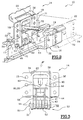
- the system 10 comprises a plate 12 for attachment to an interior fitting element of the vehicle such as a seat, a tablet or any interior design element (not shown).
- the system 10 comprises a foot 14 of the sub-assembly, fixed on the plate 12 by life (not shown) through holes 13 of a longitudinal fixing plate 11 and vertical of the plate 12 and the holes 15 of the foot 14, also shown in Figures 2 and 3.
- the foot 14 is intended to be received, as seen also in FIG. 2, in a slide 16 which is fixed to a vehicle floor (not shown).
- the slide 16 is made from a profile, for example a drawn or drawn bar.
- the foot 14 has a body 18, which can be advantageously made of folded and welded sheet metal, substantially parallelepiped, and formed on the one hand by a housing 20, intended to receive a locking mechanism described later, and on the other hand a cover 22 for closing the foot body 18 after mounting the mechanism in the body 18.
- the cover 22 is shown in Figures 1 and 2 in ghost view.
- the housing 20 and the cover 22 include lower wings 24, symmetrical about a vertical plane median longitudinal P of the slide 16, which extend transversely and horizontally and have on their lower faces 26 of the pads 28, made of material with low coefficient of friction, intended, as seen also in Figure 2, to allow the support of the foot 18 on two upper wings 30 of the slide 16, which extend horizontally and transversely outwards, and in part inwards, from the end edges upper side faces 32 of the slide 16.
- the pads of low material coefficient of friction 28 are carried by the body 18, which reduces their length to the longitudinal dimension of the body 18, thereby significantly lowering the manufacturing costs as opposed to a design where the pads 28 would extend longitudinally over the entire length upper wings 30 of the slide 16.
- the housing 20 of the foot 18 receives in vertical sliding, in a housing parallelepiped 34, a first slide 36 whose longitudinal and transverse dimensions are such that, when the cover 22 closes the housing 20 of the foot 18, the slide 36 is guided in its vertical movements on the one hand by a longitudinal face 38 of the housing 20 and by the cover 22 and, on the other hand by pressing two of its faces vertical transverse 43 on two transverse faces 40 of the housing 20, shown in Figure 3.
- the slide 36 can only move in the vertical direction relative to at foot 18, between two extreme positions defined by a horizontal upper face 39 of the housing 20 and a tab lower horizontal 41 of the housing 20.
- the slide 36 has substantially the shape of a U rectangular upside down, which receives in an inner part and upper between its vertical branches and parallel 44 a support plate 42 welded to the slide 36, shown frontally in Figure 3 and described later in reference to Figure 4A.
- the slide 36 comprises, at lower ends 46 of branches 44 of U, two longitudinal and coaxial bores 48, of longitudinal axis median located in the plane P of the slide 16.
- the holes longitudinal 48 are intended to receive a longitudinal axis 50 on which are threaded five locking members 52 received longitudinally between branches 44 of the U and capable of pivot freely around said axis 50, occupying by example an assembled locked angular position, visible in Figure 2.
- the alignment of the locking members in association with the control means form two combs 53, represented in FIG. 1, comprising respectively two and three organs.
- the combs 53 can each be made in one piece by molding, forging, and / or machining.
- the slide 16 has in one direction longitudinal of the teeth 17 which extend transversely to the interior on interior faces 21 of its upper wings 30, forming along the length of the slide 16 a rack 19, and which are intended to receive the parts upper locking members 52 of the combs 53.
- the first slide 36 receives between its branches 44 a second slide 56, capable of sliding vertically in the first slide by pressing two guide faces 55 transverse verticals between the branches 44 of the first slide 36.
- the first slide 36 and the second slide 56 are made of folded and welded sheet metal or are molded parts, which reduces considerably the manufacturing costs.
- the second slide 56 also has at its lower end two vertical transverse legs 58, advantageously carrying the guide faces 55, which are longitudinally drilled through holes 60 of a rod longitudinal 62, intended to pass through curved lights 64 of the aforementioned bodies 52.
- the transverse tabs 58 are also pierced with oblong holes 66, which open vertically at the ends lower 54 of the legs 58 of the slide 56, and the diameter corresponds to that of the longitudinal axis 50 which receives the locking members 52 of the combs 53, so that the second slide 56 is guided vertically on the one hand by the legs 44 of the first slide 36, and on the other hand by the axis 50 on which the legs 58 are guided in sliding through the oblong holes 66.
- the second slide 56 is resiliently biased towards the bottom relative to the first slide 36 via a spring 67 bearing on the one hand on a plate horizontal transverse 68 located at the upper end of the second slide 56 and, on the other hand, under a plate upper horizontal transverse 70 situated at the end upper of the support plate 42 of the first slide 36.
- the foot body 18 has on the longitudinal face 34 of the housing 20 and on the cover 22 two coaxial bearings 72 of a control shaft 74 which crosses the body 18 and the cover 22 of the foot 14, and which carries two cams 76 and 78 linked in rotation to the shaft 74 to control the movements of the two slides 36 and 56, and which will be described later.
- the control shaft 74 has, at its end located on the side of the cover 22, an operating rod 75 for allow a user to rotate it in the both directions.
- control shaft 74 crosses a vertical oblong hole 80 of the first slide 36 and a vertical oblong hole 82 of the second slide 56, which are combined in the view of FIG. 3.
- the second cam 76 is intended to act on the second slide 56 by pressing under the underside of its transverse plate 68
- first cam 78 is intended to act on the first slide 36 by through the support plate 42 by cooperating with horizontal and transverse bearing surfaces 84 and 86 which are illustrated in Figure 4A.
- the slide 56 is mounted in the slide 36, which slide 36 is mounted in the body 18.
- Figure 2 shows the system 10 in position locking assembly.
- the second slide 56 is received in the parallelepiped housing 34 of the housing 20 between the face longitudinal 38 of the housing 20 and the cover 22 inside the first slide 36 which is itself received in the housing 20.
- the locking members 52 of the combs 53 are carried by the longitudinal axis 50 which is immobilized in its movements transverse through the longitudinal holes 48 of the first slide 36, and is immobilized longitudinally by fastening means 51 such as elastic rings or, in variant (not shown), a screw / nut system.
- the locking members 52 of the combs 53 are by elsewhere crossed by the longitudinal rod 62 which occupies a determined position in the slots 64 of the organs 52, of so the upper parts of the locking members 52 of the combs 53 extend transversely outwards in the slide 16 between the teeth 17 of the rack 19.
- the position of the longitudinal rod 62 in the lights 64 will described later with reference to Figures 4A, 4B, and 4C.
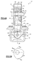
- FIG. 4A represents the system 10 in the locked position.
- the first cam 78 is in an angular position such that its cam surface with the greatest eccentricity, referenced P 78 in FIG. 5A, is turned upwards bearing on the face upper 84 of the support plate 42 of the slide 36 so that the slide 36 abuts upwards under the horizontal upper face 39 of the housing 20.
- the distance between the bearing surfaces upper 84 and lower 86 of the backing plate 42 is equal to the vertical diameter of the cam 78. Consequently the position of the first slide 36 is defined so unequivocal and free of play. The same is true of the position locked organs 52.
- the second cam 76 is in turn in an angular position such that its cam surface with the greatest eccentricity P 76 faces downward and does not act on the transverse plate 68 of the second slide 56, which is consequently brought back by relative to the first slide 36 downwards using the return spring 67.
- the locking members 52 of the combs 53 have in the transverse plane P 'a profile in the form of a drop of water and are threaded on the axis 50 in the vicinity of their lower end of larger dimensions 90.
- the locking members 52 of combs 53 are arranged alternately on the longitudinal axis 50, so that two consecutive organs 52 cooperate with two opposite spaces between two teeth 17 of the rack 19.
- the organs 52 comprise at their other end 92 of the active upper parts 94 which are received between the teeth 17 of the rack 19.
- the teeth 17 of the rack 19, seen in the transverse plane P ' have a substantially profile triangular so as to favor the rapid extraction of locking members 52 of the combs 53 when these will, as will be described later, lead to retreat.
- the teeth 17 of the rack 19 may have a profile in the form of parallelogram allowing better resistance to longitudinal tearing efforts of the foot 14.
- the slide 56 is in its low stop position relative to the slide 36, so that the longitudinal rod 62 is received in abutment with the end 96 of the lights 64 of the organs 52, which end 96 is opposite to the active parts 94 of said organs 52.
- the lights 64 are substantially arcuate circle and are not centered on axis 50. In this way, the distance E between the longitudinal rod 62 and the longitudinal axis 50 is minimal and the support of the longitudinal rod 62 in abutment at bottom of the end 96 of the lights 64 holds the organs 52 in a position of maximum transverse dimensions.
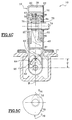
- FIG. 4B illustrates the configuration of the system 10 when a user has carried out a rotation of the control shaft 74, using the lever 75 following an hourly rotation of a quarter turn by considering FIGS. 5A and 5B.
- the portion of greatest eccentricity P 78 of the first cam 78 is in abutment on the lower bearing surface 86 of the support plate 42, so that the first slide 36 occupies a low position in which the active parts 94 of the locking members 52 of the combs 53 are no longer received between the teeth 17, but released below.
- the part of least eccentricity M 78 of the first cam 78 is in abutment on the upper bearing surface 84 of the support plate 42 so that it accompanies the movement of the slider 36 in the foot 18 while preventing the slider 36 to go back into the foot 18.
- the position of the slide 36 relative to the foot 18 is therefore defined vertically unequivocally in the low position.
- the distance between the upper bearing surfaces 84 and lower 86 of the support plate 42 is in the position of adjustment, equal to the vertical diameter of the cam 78.
- the second cam 76 is in an angular position in which it is flush with the transverse plate 68 of the second slide 56 via its part of least eccentricity M 76 , the slider 56 occupying with respect to the slider 36 a lower lower position similar to that described with reference to FIG. 4A.
- the locking members 52 of the combs 53 have maximum transverse dimensions, while being released from the teeth 17 of the rack 19, allowing thus the longitudinal adjustment of the system 10 in the slide 16.
- This position corresponds to an adjustment position longitudinal, for example, when a user wishes to adjust the longitudinal position of a seat or a sub-assembly interior fittings of the vehicle in the passenger compartment of the vehicle.
- the weight of the seat or sub-assembly of the interior layout of the vehicle plates the foot 18 against the upper wings 30 of the slide 16 via pads 28 and foot 18 can therefore only move longitudinally.
- the maximum transverse size of the locking members 52 of the combs 53 guarantees advantageously, in the event that an effort is exerted vertically upwards on foot 18, as in the case a violent shock, that it does not leave the slide 16.
- FIG. 4C represents the system 10 in the position of vertical engagement or disengagement of the foot 18.
- the first cam 78 is in an angular position such that its part with the highest eccentricity P 78 acts on the horizontal lower face 86 in a manner similar to that described with reference to FIG. 4B.
- the part with the highest eccentricity P 78 is therefore supported on the lower face 86 of the support plate 42 of the first slide 36.
- the longitudinal rod 62 has slipped inside lights 64 made in the locking members 52 of the combs 53 to reach a stop position 97, which is the opposite of the previous position 96 in the lights 64.
- the sliding bearing of the longitudinal rod 62 in the lights 64 of the organs 52 during the rotation of the shaft 74 causes transverse inward retraction of the organs 52, and the foot 18 is no longer while pressing on the slide 16.
- the foot 18 can then be removed from the slide 16.
- the ascent of the second slide 56 is perfectly ensured at the inside of the foot 18 through the cooperation between the oblong holes 54 which receive the longitudinal axis 50 integral with the first slide 36, the slides being of more guided on the shaft 74 by the oblong holes 80 and 82.
- the part with the highest eccentricity P 76 of the cam 76 occupies a very small angular portion of the cam 76, which results in an unstable equilibrium of the cam 76 on the plate. transverse 68 of the second slide 56.
- the slope of the profile of the cam 78 is steeper on the right side of the part with the highest eccentricity P 76 of the cam 76.
- control axis 74 can be rotated counterclockwise by a spiral spring linked to the housing 20 and linked in rotation to the axis of control 74 so that its rest position corresponds to the locked position of foot 18 in the slide 16.
- this position corresponds to a use in engagement or in release of the system 10 in the slide 16 linked to the vehicle.
- This position allows by example of removing or adding a subset such as previously described with reference to FIG. 1 so as to be able to use the passenger compartment of the vehicle concerned with a great modularity.
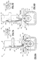
- FIGS. 6A, 6B, 7A, and 7B illustrate a mode of alternative embodiment of system 10 as above described.
- the body 18 comprises a third slide 93 for blocking the control shaft 74 intended to hold the organs of locking 52 of the combs 53 in the retracted position or retraction of clearance when foot 14 is extracted vertically from the slide 16.
- Locking slide 93 is vertically movable between the walls of the housing 20 and the first slide 36 (not shown in Figures 6A, 6B).
- the blocking slide 93 of the control shaft 74 has a transverse tab lower 98 which, when the body 18 is in contact with the slide 16, is received in a housing 100 made transversely in the lower wing 24 of the housing 20.
- the blocking slide 93 of the control shaft 74 has a recess 102 allowing the passage of the control shaft 74.
- a second transverse tab 104 facing inside the slide 16 and located at the lower end of the slide 93 compresses a return spring 96 of the slide 93 against the horizontal lower tab 41 of the housing 20.
- the shaft of control 74 comprises, in the vertical longitudinal plane of the blocking slide 93, a third cam 106.
- the recess 102 has a lug profile intended to cooperate with the cam 106 of the shaft 74 so that when the slide 93 for locking the control shaft 74 is pulled back down into a stop position by the spring 96, a lug 108 belonging to the slide 93 comes in contact with a notch 110 carried by the integral cam 106 of the control shaft 74 to and prevent its rotation in clockwise. In this way, as shown in FIGS.
- control shaft 74 is immobilized in rotation as long as the tab 98 of the slider 94 for blocking the control shaft is not pressed again on the transverse wings 30 of the slide 16, thus preventing any risk of transverse expansion towards the outside of the organs 52 when the foot 14 is not inserted in the slide 16, as shown in Figure 6B.
- FIGS. 6A and 6B also illustrate a mode of variant of the slide 16.
- the rack 19 of the slide 16 is produced by two plates 112, hollowed out at regular intervals, and arranged according to the direction longitudinal of the slide 16 and inclined at a similar angle to that of the teeth 17 described with reference to the figures previous, to cooperate with hook ends 114 located at the ends of the active parts 94 of the organs 52.
- the teeth 17 of the rack consist of the areas of material between two recesses of the plates 112.
Landscapes
- Engineering & Computer Science (AREA)
- Aviation & Aerospace Engineering (AREA)
- Transportation (AREA)
- Mechanical Engineering (AREA)
- Seats For Vehicles (AREA)
- Toys (AREA)
- Orthopedics, Nursing, And Contraception (AREA)
Applications Claiming Priority (2)
| Application Number | Priority Date | Filing Date | Title |
|---|---|---|---|
| FR9804244A FR2777049B1 (fr) | 1998-04-06 | 1998-04-06 | Systeme d'arrimage modulable a commande par cames |
| FR9804244 | 1998-04-06 |
Publications (2)
| Publication Number | Publication Date |
|---|---|
| EP0949111A1 true EP0949111A1 (de) | 1999-10-13 |
| EP0949111B1 EP0949111B1 (de) | 2004-03-17 |
Family
ID=9524896
Family Applications (1)
| Application Number | Title | Priority Date | Filing Date |
|---|---|---|---|
| EP19990400816 Expired - Lifetime EP0949111B1 (de) | 1998-04-06 | 1999-04-02 | Modulares Befestigungssystem mit Nockensteuerung |
Country Status (4)
| Country | Link |
|---|---|
| EP (1) | EP0949111B1 (de) |
| DE (1) | DE69915528T2 (de) |
| ES (1) | ES2213987T3 (de) |
| FR (1) | FR2777049B1 (de) |
Cited By (13)
| Publication number | Priority date | Publication date | Assignee | Title |
|---|---|---|---|---|
| EP1176047A1 (de) * | 2000-07-27 | 2002-01-30 | Grupo Antolin-Ingenieria, S.A. | Vorrichtung zum Führen und Verankern herausnehmbarer Fahrzeugsitze |
| WO2003004304A1 (de) * | 2001-06-29 | 2003-01-16 | Werner Badorrek | Einrichtung zur verstellung und arretierung einer mit einer struktur, z.b. mit einem boden eines verkehrs- oder transportmittels verbindbaren baueinheit |
| FR2829439A1 (fr) * | 2001-09-07 | 2003-03-14 | Faurecia Sieges Automobile | Pietement de siege de vehicule, siege comportant un tel pietement et ensemble d'assise comportant un tel siege |
| FR2834944A1 (fr) * | 2002-01-18 | 2003-07-25 | Peugeot Citroen Automobiles Sa | Systeme de fixation d'un siege automobile |
| FR2835790A1 (fr) * | 2002-02-08 | 2003-08-15 | Antolin Grupo Ing Sa | Dispositif de calage vertical et automatique d'un siege de vehicule |
| FR2856018A1 (fr) * | 2003-06-10 | 2004-12-17 | Faurecia Sieges Automobile | Dispositif de fixation d'un siege sur un plancher de vehicule et siege de vehicule comprenant un tel dispositif de fixation |
| EP1980446A1 (de) * | 2007-04-13 | 2008-10-15 | BOS GmbH & Co. KG | Vorrichtung zum Befestigen von Ladegut in einem Transportmittel |
| GB2501912A (en) * | 2012-05-10 | 2013-11-13 | Koller Engineering Ltd | Vehicle seat anchorage assembly |
| WO2018029410A1 (fr) * | 2016-08-11 | 2018-02-15 | Psa Automobiles Sa | Ensemble coulissant pour habitacle de vehicule automobile a confort d'utilisation ameliore |
| CN109185286A (zh) * | 2018-10-29 | 2019-01-11 | 深圳市格特隆光电股份有限公司 | 一种杠杆式led显示箱体锁固机构 |
| EP3597488A1 (de) | 2018-07-04 | 2020-01-22 | Magna Seating (Germany) GmbH | Arretier- und kontaktierungssystem zum elektrischen verbinden eines bordnetzes eines kraftfahrzeugs mit einem entnehmbaren fahrzeugsitz oder einer sitzanlage |
| CN115095780A (zh) * | 2022-07-18 | 2022-09-23 | 北京精准医械科技有限公司 | 连接机构及支撑装置 |
| CN120517283A (zh) * | 2025-07-24 | 2025-08-22 | 常州卓骏汽车系统有限公司 | 零重力座椅及控制方法 |
Families Citing this family (7)
| Publication number | Priority date | Publication date | Assignee | Title |
|---|---|---|---|---|
| DE102004035480B4 (de) | 2004-07-14 | 2018-03-01 | Volkswagen Ag | Schienenanordnung |
| DE102006061508A1 (de) * | 2006-12-15 | 2008-06-26 | Bos Gmbh & Co. Kg | Vorrichtung zum Fixieren eines Lademittels |
| DE102007037528A1 (de) | 2007-08-09 | 2009-02-12 | Magna Seating (Germany) Gmbh | Sitzbeschlag |
| DE102007038712A1 (de) | 2007-08-14 | 2009-02-19 | Magna Seating (Germany) Gmbh | Befestigungsbeschlag |
| DE102010063615B4 (de) | 2010-08-23 | 2021-07-22 | Adient Luxembourg Holding S.À R.L. | Längsverstellvorrichtung für einen Fahrzeugsitz mit trennbarer Ober- und Unterschiene |
| CN107280726B (zh) * | 2017-07-10 | 2023-06-23 | 天津海迈医用科技有限公司 | 连续调节式压脉带装置 |
| DE102018207170B4 (de) * | 2018-05-08 | 2020-12-17 | Magna Seating (Germany) Gmbh | Kontaktierungssystem zum elektrischen Verbinden eines Bordnetzes eines Kraftfahrzeugs mit einem entnehmbaren Fahrzeugsitz oder einer Sitzanlage |
Citations (3)
| Publication number | Priority date | Publication date | Assignee | Title |
|---|---|---|---|---|
| US5236153A (en) * | 1992-06-25 | 1993-08-17 | Laconte Richard J | Longitudinal floating pivot track fitting |
| DE19520959A1 (de) * | 1995-06-08 | 1996-12-12 | Albert Muehlenberg Apparatebau | Schnellwechselbeschlag |
| DE29803620U1 (de) * | 1998-03-03 | 1998-05-07 | Fairchild Fasteners Europe - Camloc GmbH, 65779 Kelkheim | Sitzbefestigung |
-
1998
- 1998-04-06 FR FR9804244A patent/FR2777049B1/fr not_active Expired - Fee Related
-
1999
- 1999-04-02 ES ES99400816T patent/ES2213987T3/es not_active Expired - Lifetime
- 1999-04-02 DE DE69915528T patent/DE69915528T2/de not_active Expired - Lifetime
- 1999-04-02 EP EP19990400816 patent/EP0949111B1/de not_active Expired - Lifetime
Patent Citations (3)
| Publication number | Priority date | Publication date | Assignee | Title |
|---|---|---|---|---|
| US5236153A (en) * | 1992-06-25 | 1993-08-17 | Laconte Richard J | Longitudinal floating pivot track fitting |
| DE19520959A1 (de) * | 1995-06-08 | 1996-12-12 | Albert Muehlenberg Apparatebau | Schnellwechselbeschlag |
| DE29803620U1 (de) * | 1998-03-03 | 1998-05-07 | Fairchild Fasteners Europe - Camloc GmbH, 65779 Kelkheim | Sitzbefestigung |
Cited By (20)
| Publication number | Priority date | Publication date | Assignee | Title |
|---|---|---|---|---|
| EP1176047A1 (de) * | 2000-07-27 | 2002-01-30 | Grupo Antolin-Ingenieria, S.A. | Vorrichtung zum Führen und Verankern herausnehmbarer Fahrzeugsitze |
| FR2812251A1 (fr) * | 2000-07-27 | 2002-02-01 | Antolin Grupo Ing Sa | Dispositif de guidage et d'ancrage pour siege amovible de vehicule |
| WO2003004304A1 (de) * | 2001-06-29 | 2003-01-16 | Werner Badorrek | Einrichtung zur verstellung und arretierung einer mit einer struktur, z.b. mit einem boden eines verkehrs- oder transportmittels verbindbaren baueinheit |
| FR2829439A1 (fr) * | 2001-09-07 | 2003-03-14 | Faurecia Sieges Automobile | Pietement de siege de vehicule, siege comportant un tel pietement et ensemble d'assise comportant un tel siege |
| US6648394B2 (en) | 2001-09-07 | 2003-11-18 | Faurecia Sieges d′Automobile S.A. | Vehicle seat underframe, seat comprising such an underframe and seat assembly comprising such a seat |
| FR2834944A1 (fr) * | 2002-01-18 | 2003-07-25 | Peugeot Citroen Automobiles Sa | Systeme de fixation d'un siege automobile |
| FR2835790A1 (fr) * | 2002-02-08 | 2003-08-15 | Antolin Grupo Ing Sa | Dispositif de calage vertical et automatique d'un siege de vehicule |
| US6736458B2 (en) | 2002-02-08 | 2004-05-18 | Grupo Antolin-Ingenieria, S.A. | Device for the vertical and automatic wedging of a vehicle seat |
| EP1334865A3 (de) * | 2002-02-08 | 2004-06-09 | Grupo Antolin-Ingenieria, S.A. | Automatisch Vertikalverkeilungseinrichtung eines Fahrzeugsitzes |
| FR2856018A1 (fr) * | 2003-06-10 | 2004-12-17 | Faurecia Sieges Automobile | Dispositif de fixation d'un siege sur un plancher de vehicule et siege de vehicule comprenant un tel dispositif de fixation |
| EP1980446A1 (de) * | 2007-04-13 | 2008-10-15 | BOS GmbH & Co. KG | Vorrichtung zum Befestigen von Ladegut in einem Transportmittel |
| GB2501912A (en) * | 2012-05-10 | 2013-11-13 | Koller Engineering Ltd | Vehicle seat anchorage assembly |
| WO2018029410A1 (fr) * | 2016-08-11 | 2018-02-15 | Psa Automobiles Sa | Ensemble coulissant pour habitacle de vehicule automobile a confort d'utilisation ameliore |
| FR3054984A1 (fr) * | 2016-08-11 | 2018-02-16 | Peugeot Citroen Automobiles Sa | Ensemble coulissant pour habitacle de vehicule automobile a confort d'utilisation ameliore |
| CN109562713A (zh) * | 2016-08-11 | 2019-04-02 | 标致雪铁龙汽车股份有限公司 | 用于机动车辆的乘客舱的使用舒适度改善的滑动组件 |
| CN109562713B (zh) * | 2016-08-11 | 2021-07-06 | 标致雪铁龙汽车股份有限公司 | 用于机动车辆的乘客舱的使用舒适度改善的滑动组件 |
| EP3597488A1 (de) | 2018-07-04 | 2020-01-22 | Magna Seating (Germany) GmbH | Arretier- und kontaktierungssystem zum elektrischen verbinden eines bordnetzes eines kraftfahrzeugs mit einem entnehmbaren fahrzeugsitz oder einer sitzanlage |
| CN109185286A (zh) * | 2018-10-29 | 2019-01-11 | 深圳市格特隆光电股份有限公司 | 一种杠杆式led显示箱体锁固机构 |
| CN115095780A (zh) * | 2022-07-18 | 2022-09-23 | 北京精准医械科技有限公司 | 连接机构及支撑装置 |
| CN120517283A (zh) * | 2025-07-24 | 2025-08-22 | 常州卓骏汽车系统有限公司 | 零重力座椅及控制方法 |
Also Published As
| Publication number | Publication date |
|---|---|
| FR2777049B1 (fr) | 2000-06-02 |
| FR2777049A1 (fr) | 1999-10-08 |
| ES2213987T3 (es) | 2004-09-01 |
| DE69915528T2 (de) | 2005-03-03 |
| EP0949111B1 (de) | 2004-03-17 |
| DE69915528D1 (de) | 2004-04-22 |
Similar Documents
| Publication | Publication Date | Title |
|---|---|---|
| EP0949111B1 (de) | Modulares Befestigungssystem mit Nockensteuerung | |
| EP0947380B1 (de) | Auf dem Schienenboden eingebaute Zahnstangenvorrichtung | |
| EP1334865A2 (de) | Automatisch Vertikalverkeilungseinrichtung eines Fahrzeugsitzes | |
| EP0265316A1 (de) | Verriegelungssystem für eine lineare Schnellverstell- und Blockiereinrichtung eines beweglichen Teiles gegenüber einem festen Teil | |
| FR2963586A1 (fr) | Glissiere pour siege de vehicule automobile a verrouillage lateral sans jeu | |
| CH640421A5 (en) | Ski safety binding | |
| FR2858786A1 (fr) | Siege auto pour enfant, pivotant entre une position face a la route et une position face a une portiere, a retour automatique en position face a la route | |
| EP0800952B1 (de) | Kraftfahrzeugsitz, nach vorn bewegbar, um zu einem Hinterraum Zugang zu haben | |
| EP0949112B1 (de) | Modulares Befestigungssystem im Innenraum eines Kraftfahrzeuges | |
| EP2930130B1 (de) | Keilvorrichtung als wegfahrsperre für fahrzeug | |
| EP0234160A1 (de) | Geradlinige Winde mit Sperrung durch Rollen in beliebigen Stellungen | |
| EP0532378B1 (de) | Rückhaltevorrichtung für einen, auf dem mittleren Rücksitz eines Fahrzeuges sitzenden, Insassen | |
| FR2930485A1 (fr) | Siege automobile pour enfant | |
| EP0747256B1 (de) | Drehbarer Sicherheitsitz | |
| FR2554695A1 (fr) | Mecanisme d'inclinaison pour siege, et notamment pour siege d'automobile | |
| FR2828149A1 (fr) | Dispositif de verrouillage notamment d'un dossier de siege arriere rabattable de vehicule automobile | |
| EP0344033B1 (de) | Verriegelungsvorrichtung für Sitzführungsschiene von Fahrzeugen | |
| EP0922606B1 (de) | Anordnung für einen ausnehmbaren und in Längsrichtung verstellbaren Sitz im Innenraum eines Kraftfahrzeuges | |
| FR2656858A1 (fr) | Structure unitaire deplacable de calage ou de soutien d'un vehicule routier par ses roues. | |
| EP0293282A1 (de) | Lageverstellvorrichtung eines Gurtumlenkbeschlags, insbesondere für einen Kraftfahrzeugsicherheitsgurt | |
| EP1097846A1 (de) | System zur Befestigung von Gegenständen im Inneren eines Kraftfahrzeugs sowie gleitende Ankerelemente hierfür | |
| EP0296940B1 (de) | Verstellvorrichtung für einen Gurtumlenkbeschlag, insbesondere für Kraftfahrzeugsicherheitsgurte | |
| EP0296026B1 (de) | Lageverstellvorrichtung eines Gurtumlenkbeschlags, insbesondere für Sicherheitsgurte von Kraftfahrzeugen | |
| EP0276186A1 (de) | Vorrichtung zur Trägheitsverriegelung für Fahrzeugsitze | |
| FR2989942A1 (fr) | Systeme de verrouillage d'une patte d'ancrage d'un organe amovible, notamment d'un tendelet pour vehicule, et vehicule correspondant |
Legal Events
| Date | Code | Title | Description |
|---|---|---|---|
| PUAI | Public reference made under article 153(3) epc to a published international application that has entered the european phase |
Free format text: ORIGINAL CODE: 0009012 |
|
| AK | Designated contracting states |
Kind code of ref document: A1 Designated state(s): DE ES GB IT |
|
| AX | Request for extension of the european patent |
Free format text: AL;LT;LV;MK;RO;SI |
|
| 17P | Request for examination filed |
Effective date: 20000405 |
|
| AKX | Designation fees paid |
Free format text: DE ES GB IT |
|
| RAP1 | Party data changed (applicant data changed or rights of an application transferred) |
Owner name: RENAULT S.A.S. |
|
| GRAH | Despatch of communication of intention to grant a patent |
Free format text: ORIGINAL CODE: EPIDOS IGRA |
|
| GRAS | Grant fee paid |
Free format text: ORIGINAL CODE: EPIDOSNIGR3 |
|
| GRAA | (expected) grant |
Free format text: ORIGINAL CODE: 0009210 |
|
| AK | Designated contracting states |
Kind code of ref document: B1 Designated state(s): DE ES GB IT |
|
| REG | Reference to a national code |
Ref country code: GB Ref legal event code: FG4D Free format text: NOT ENGLISH |
|
| REF | Corresponds to: |
Ref document number: 69915528 Country of ref document: DE Date of ref document: 20040422 Kind code of ref document: P |
|
| GBT | Gb: translation of ep patent filed (gb section 77(6)(a)/1977) |
Effective date: 20040715 |
|
| REG | Reference to a national code |
Ref country code: ES Ref legal event code: FG2A Ref document number: 2213987 Country of ref document: ES Kind code of ref document: T3 |
|
| PLBE | No opposition filed within time limit |
Free format text: ORIGINAL CODE: 0009261 |
|
| STAA | Information on the status of an ep patent application or granted ep patent |
Free format text: STATUS: NO OPPOSITION FILED WITHIN TIME LIMIT |
|
| 26N | No opposition filed |
Effective date: 20041220 |
|
| PGFP | Annual fee paid to national office [announced via postgrant information from national office to epo] |
Ref country code: DE Payment date: 20120420 Year of fee payment: 14 |
|
| PGFP | Annual fee paid to national office [announced via postgrant information from national office to epo] |
Ref country code: GB Payment date: 20120419 Year of fee payment: 14 |
|
| PGFP | Annual fee paid to national office [announced via postgrant information from national office to epo] |
Ref country code: IT Payment date: 20120424 Year of fee payment: 14 |
|
| PGFP | Annual fee paid to national office [announced via postgrant information from national office to epo] |
Ref country code: ES Payment date: 20120425 Year of fee payment: 14 |
|
| GBPC | Gb: european patent ceased through non-payment of renewal fee |
Effective date: 20130402 |
|
| PG25 | Lapsed in a contracting state [announced via postgrant information from national office to epo] |
Ref country code: DE Free format text: LAPSE BECAUSE OF NON-PAYMENT OF DUE FEES Effective date: 20131101 Ref country code: GB Free format text: LAPSE BECAUSE OF NON-PAYMENT OF DUE FEES Effective date: 20130402 |
|
| REG | Reference to a national code |
Ref country code: DE Ref legal event code: R119 Ref document number: 69915528 Country of ref document: DE Effective date: 20131101 |
|
| PG25 | Lapsed in a contracting state [announced via postgrant information from national office to epo] |
Ref country code: IT Free format text: LAPSE BECAUSE OF NON-PAYMENT OF DUE FEES Effective date: 20130402 |
|
| REG | Reference to a national code |
Ref country code: ES Ref legal event code: FD2A Effective date: 20150710 |
|
| PG25 | Lapsed in a contracting state [announced via postgrant information from national office to epo] |
Ref country code: ES Free format text: LAPSE BECAUSE OF NON-PAYMENT OF DUE FEES Effective date: 20130403 |