EP0949131A2 - Vorrichtung zur Kraftfahrzeug-Laufverhaltens-Steuerung mit mathematischem Reifenmodell - Google Patents
Vorrichtung zur Kraftfahrzeug-Laufverhaltens-Steuerung mit mathematischem Reifenmodell Download PDFInfo
- Publication number
- EP0949131A2 EP0949131A2 EP99106952A EP99106952A EP0949131A2 EP 0949131 A2 EP0949131 A2 EP 0949131A2 EP 99106952 A EP99106952 A EP 99106952A EP 99106952 A EP99106952 A EP 99106952A EP 0949131 A2 EP0949131 A2 EP 0949131A2
- Authority
- EP
- European Patent Office
- Prior art keywords
- calculated
- force
- difference
- slip ratio
- yaw moment
- Prior art date
- Legal status (The legal status is an assumption and is not a legal conclusion. Google has not performed a legal analysis and makes no representation as to the accuracy of the status listed.)
- Granted
Links
- 230000008859 change Effects 0.000 claims description 8
- 238000013459 approach Methods 0.000 abstract description 3
- 125000004122 cyclic group Chemical group 0.000 abstract description 2
- 230000004069 differentiation Effects 0.000 abstract description 2
- 230000006399 behavior Effects 0.000 description 33
- 230000001133 acceleration Effects 0.000 description 13
- 238000004364 calculation method Methods 0.000 description 7
- 238000004458 analytical method Methods 0.000 description 4
- 230000004048 modification Effects 0.000 description 4
- 238000012986 modification Methods 0.000 description 4
- 230000007423 decrease Effects 0.000 description 3
- 230000003068 static effect Effects 0.000 description 3
- 235000015429 Mirabilis expansa Nutrition 0.000 description 2
- 244000294411 Mirabilis expansa Species 0.000 description 2
- 238000010276 construction Methods 0.000 description 2
- 230000005484 gravity Effects 0.000 description 2
- 235000013536 miso Nutrition 0.000 description 2
- 238000012545 processing Methods 0.000 description 2
- 230000007306 turnover Effects 0.000 description 2
- 230000001143 conditioned effect Effects 0.000 description 1
- 238000007796 conventional method Methods 0.000 description 1
- 230000003247 decreasing effect Effects 0.000 description 1
- 230000000994 depressogenic effect Effects 0.000 description 1
- 238000009826 distribution Methods 0.000 description 1
- 230000006870 function Effects 0.000 description 1
- 238000010348 incorporation Methods 0.000 description 1
- 238000000034 method Methods 0.000 description 1
- 230000008569 process Effects 0.000 description 1
- 238000004088 simulation Methods 0.000 description 1
- 238000009987 spinning Methods 0.000 description 1
- 230000000087 stabilizing effect Effects 0.000 description 1
- 239000000725 suspension Substances 0.000 description 1
- 230000001052 transient effect Effects 0.000 description 1
- 230000001960 triggered effect Effects 0.000 description 1
- 230000028838 turning behavior Effects 0.000 description 1
- 238000009827 uniform distribution Methods 0.000 description 1
Images

Classifications
-
- B—PERFORMING OPERATIONS; TRANSPORTING
- B60—VEHICLES IN GENERAL
- B60T—VEHICLE BRAKE CONTROL SYSTEMS OR PARTS THEREOF; BRAKE CONTROL SYSTEMS OR PARTS THEREOF, IN GENERAL; ARRANGEMENT OF BRAKING ELEMENTS ON VEHICLES IN GENERAL; PORTABLE DEVICES FOR PREVENTING UNWANTED MOVEMENT OF VEHICLES; VEHICLE MODIFICATIONS TO FACILITATE COOLING OF BRAKES
- B60T8/00—Arrangements for adjusting wheel-braking force to meet varying vehicular or ground-surface conditions, e.g. limiting or varying distribution of braking force
- B60T8/17—Using electrical or electronic regulation means to control braking
- B60T8/1755—Brake regulation specially adapted to control the stability of the vehicle, e.g. taking into account yaw rate or transverse acceleration in a curve
-
- B—PERFORMING OPERATIONS; TRANSPORTING
- B60—VEHICLES IN GENERAL
- B60W—CONJOINT CONTROL OF VEHICLE SUB-UNITS OF DIFFERENT TYPE OR DIFFERENT FUNCTION; CONTROL SYSTEMS SPECIALLY ADAPTED FOR HYBRID VEHICLES; ROAD VEHICLE DRIVE CONTROL SYSTEMS FOR PURPOSES NOT RELATED TO THE CONTROL OF A PARTICULAR SUB-UNIT
- B60W10/00—Conjoint control of vehicle sub-units of different type or different function
- B60W10/18—Conjoint control of vehicle sub-units of different type or different function including control of braking systems
- B60W10/184—Conjoint control of vehicle sub-units of different type or different function including control of braking systems with wheel brakes
-
- B—PERFORMING OPERATIONS; TRANSPORTING
- B60—VEHICLES IN GENERAL
- B60T—VEHICLE BRAKE CONTROL SYSTEMS OR PARTS THEREOF; BRAKE CONTROL SYSTEMS OR PARTS THEREOF, IN GENERAL; ARRANGEMENT OF BRAKING ELEMENTS ON VEHICLES IN GENERAL; PORTABLE DEVICES FOR PREVENTING UNWANTED MOVEMENT OF VEHICLES; VEHICLE MODIFICATIONS TO FACILITATE COOLING OF BRAKES
- B60T2270/00—Further aspects of brake control systems not otherwise provided for
- B60T2270/86—Optimizing braking by using ESP vehicle or tyre model
-
- B—PERFORMING OPERATIONS; TRANSPORTING
- B60—VEHICLES IN GENERAL
- B60W—CONJOINT CONTROL OF VEHICLE SUB-UNITS OF DIFFERENT TYPE OR DIFFERENT FUNCTION; CONTROL SYSTEMS SPECIALLY ADAPTED FOR HYBRID VEHICLES; ROAD VEHICLE DRIVE CONTROL SYSTEMS FOR PURPOSES NOT RELATED TO THE CONTROL OF A PARTICULAR SUB-UNIT
- B60W50/00—Details of control systems for road vehicle drive control not related to the control of a particular sub-unit, e.g. process diagnostic or vehicle driver interfaces
- B60W2050/0001—Details of the control system
- B60W2050/0019—Control system elements or transfer functions
- B60W2050/0028—Mathematical models, e.g. for simulation
-
- B—PERFORMING OPERATIONS; TRANSPORTING
- B60—VEHICLES IN GENERAL
- B60W—CONJOINT CONTROL OF VEHICLE SUB-UNITS OF DIFFERENT TYPE OR DIFFERENT FUNCTION; CONTROL SYSTEMS SPECIALLY ADAPTED FOR HYBRID VEHICLES; ROAD VEHICLE DRIVE CONTROL SYSTEMS FOR PURPOSES NOT RELATED TO THE CONTROL OF A PARTICULAR SUB-UNIT
- B60W2520/00—Input parameters relating to overall vehicle dynamics
- B60W2520/10—Longitudinal speed
-
- B—PERFORMING OPERATIONS; TRANSPORTING
- B60—VEHICLES IN GENERAL
- B60W—CONJOINT CONTROL OF VEHICLE SUB-UNITS OF DIFFERENT TYPE OR DIFFERENT FUNCTION; CONTROL SYSTEMS SPECIALLY ADAPTED FOR HYBRID VEHICLES; ROAD VEHICLE DRIVE CONTROL SYSTEMS FOR PURPOSES NOT RELATED TO THE CONTROL OF A PARTICULAR SUB-UNIT
- B60W2520/00—Input parameters relating to overall vehicle dynamics
- B60W2520/12—Lateral speed
- B60W2520/125—Lateral acceleration
-
- B—PERFORMING OPERATIONS; TRANSPORTING
- B60—VEHICLES IN GENERAL
- B60W—CONJOINT CONTROL OF VEHICLE SUB-UNITS OF DIFFERENT TYPE OR DIFFERENT FUNCTION; CONTROL SYSTEMS SPECIALLY ADAPTED FOR HYBRID VEHICLES; ROAD VEHICLE DRIVE CONTROL SYSTEMS FOR PURPOSES NOT RELATED TO THE CONTROL OF A PARTICULAR SUB-UNIT
- B60W2520/00—Input parameters relating to overall vehicle dynamics
- B60W2520/14—Yaw
-
- B—PERFORMING OPERATIONS; TRANSPORTING
- B60—VEHICLES IN GENERAL
- B60W—CONJOINT CONTROL OF VEHICLE SUB-UNITS OF DIFFERENT TYPE OR DIFFERENT FUNCTION; CONTROL SYSTEMS SPECIALLY ADAPTED FOR HYBRID VEHICLES; ROAD VEHICLE DRIVE CONTROL SYSTEMS FOR PURPOSES NOT RELATED TO THE CONTROL OF A PARTICULAR SUB-UNIT
- B60W2530/00—Input parameters relating to vehicle conditions or values, not covered by groups B60W2510/00 or B60W2520/00
- B60W2530/20—Tyre data
Definitions
- the present invention relates to a device for controlling a running behavior of vehicles, and more particularly, to a device for conducting such a control of a four wheeled vehicle based upon a mathematical tire model simulating the performance of longitudinal and lateral forces vs. slip ratio of the tire of each wheel.
- the tires of the wheels of vehicles such as automobiles generally exhibit a performance such as exemplarily shown in the map of Fig. 5 with respect to the relationship between the longitudinal or lateral force and the slip ratio.
- a performance such as exemplarily shown in the map of Fig. 5 with respect to the relationship between the longitudinal or lateral force and the slip ratio.
- the actual performance of each particular tire differs from the shown performance in the shape of the curves as well as in the magnitude of the scales according to its tread pattern and respective operational conditions such as a road surface condition, etc.
- Ftxi - ⁇ i 2 Ks 1-Si Si - ⁇ Wi cos ⁇ i (1 - 3 ⁇ i 2 + 2 ⁇ i 3 )
- Ftyi - ⁇ i 2 Kb tan ⁇ i 1-Si - ⁇ Wi sin ⁇ i (1 - 3 ⁇ i 2 + 2 ⁇ i 3 ) when ⁇ i ⁇ 0, or
- Ftxi and Ftyi are the longitudinal and lateral components of a force Ft
- Fig. 9 shows an example of the yaw moment applied to the vehicle body of a four wheeled vehicle by a braking of each of the four wheels when the vehicle is running out of a straight course.
- a device for controlling a running behavior of a vehicle based upon a force-slip performance of a tire the vehicle having a vehicle body, a pair of front wheels and a pair of rear wheels, and brake means for selectively applying a controlled braking force to at least either the front pair or the rear pair of the wheels bearing the tires, comprising:
- the control operation is continually effective even when the vehicle is running in such an operation range where the running behavior of the vehicle is so stabilized that some conventional running stability control devices adapted to be triggered by a certain parameter trespassing a threshold value do not yet operate.
- the above-mentioned device may further be modified such that it further comprises:
- the above-mentioned device may further be modified such that it further comprises:
- the above-mentioned device may further be modified such that the ninth means are modified to calculate the differences in the slip ratio so that a sum of the weighted sum calculated by the ninth means, the weighted sum calculated by the eleventh means and the weighted sum calculated by the twelfth means is minimized.
- the above-mentioned device may further be modified such that the third means modify the second longitudinal force, the second lateral force and the second yaw moment of the vehicle body calculated by the second means with the longitudinal force, the lateral force and the yaw moment corresponding to the output of the outside running behavior controller, so as to obtain the nominal longitudinal force, the nominal lateral force and the nominal yaw moment, respectively, by adding the longitudinal force, the lateral force and the yaw moment corresponding to the output of the outside running behavior controller to the second longitudinal force, the second lateral force and the second yaw moment , respectively.
- the third means may substantially cancel the lateral force corresponding to the output of the outside running behavior controller in obtaining the nominal lateral force.
- the device may further be modified such that the ninth means apply a variable weighting factor on each of the difference in the slip ratio of each of the at least the front pair of the wheels calculated thereby before outputting the calculated slip ratio difference such that a slip ratio difference applied with a larger weighting factor affects less in the running behavior control than a slip ratio difference applied with a smaller weighting factor, the weighting factor being varied such that, when the nominal yaw moment calculated by the third means is directed to assist a turn of the vehicle, the weighting factor on the slip ratio difference of one of the pair of front wheels serving at the inside of a turn is made larger.
- the device may further be modified such that the tenth means are adapted to cancel a braking of the rear wheels by overriding the difference of the slip ratio calculated by the ninth means when the yaw rate of the vehicle has changed its direction from a first direction conforming to a turning of the vehicle to a second direction opposite to the first direction during a turn running of the vehicle.
- FIG. 1 showing diagrammatically a vehicle in which an embodiment of the vehicle running behavior control device according to the present invention is incorporated.
- the vehicle has a vehicle body 12, and front right wheel 10FR, front left wheel 10FL, rear right wheel 10RR and rear left wheel 10RL supporting the vehicle body 12 via respective suspension means not shown in the figure.
- the front right and front left wheels 10FR and 10FL are steered by a rack-and-pinion type power steering means 16 according to rotations of a steering wheel 14 by a driver via a pair of tie rods 18R and 18L, respectively.
- a brake system generally designated by 20 includes a hydraulic circuit means 22, a brake pedal 26 adapted to be depressed by the driver, a master cylinder 28 for supplying a master cylinder pressure to the hydraulic circuit means 22 according to the depression of the brake pedal by the driver, and wheel cylinders 24FR, 24FL, 24RR and 24RL each adapted to apply a braking force to each corresponding one of the front right, front left, rear right and rear left wheels according to a supply of a hydraulic pressure thereto from the hydraulic circuit means 22.
- the hydraulic circuit means 22 are electrically controlled by electric control means 30 incorporating a microcomputer which may be of an ordinary type including a central processor unit, a read only memory, a random access memory, input and output port means and a common bus interconnecting these elements.
- electric control means 30 incorporating a microcomputer which may be of an ordinary type including a central processor unit, a read only memory, a random access memory, input and output port means and a common bus interconnecting these elements.
- the electric control means 30 are supplied with a signal indicating steering angle ⁇ inputted to the lack-and-pinion type power steering means 16 from the steering wheel 14 according to a rotation thereof by the driver from a steering angle sensor 34, a signal indicating yaw rate ⁇ of the vehicle body from a yaw rate sensor 36, a signal indicating longitudinal acceleration Gx of the vehicle body from a longitudinal acceleration sensor 38, a signal indicating lateral acceleration Gy of the vehicle body from a lateral acceleration sensor 40, a signal indicating vehicle speed V from a vehicle speed sensor 42, signals indicating vehicle wheel speeds Vwi of the front right, front left, rear right and rear left wheels from wheel speed sensors 32FR, 32FL, 32RR and 32RL, respectively, and signals indicating static loads Wsi of the front right, front left, rear right and rear left wheels from static load sensors 44fr, 44fl, 44rr and 44rl, respectively, and conduct control calculations according to the programs stored in the read only memory based upon the parameters supplied by the signals in the manner described in detail
- the vehicle running behavior control device of the present invention will be described hereinbelow in the form of its control operation of an embodiment thereof by referring to the flowchart of Fig. 2 showing the main routine of the control operation.
- the control according to the main routine is started by a closure of an ignition switch not shown in the figure and cyclically repeated therethrough during the operation of the vehicle.
- the operation of the embodiment device of the present invention is generally described so as to selectively apply a controlled braking force to both of the front pair and the real pair of the wheels, the device according to the present invention may be so constructed as to selectively apply a controlled braking force to only the front pair or the rear pair of the wheels.
- slip ratios Si of the respective wheels which are parameters to be controlled according to the present invention, are reset to zero for each initial starting.
- step 100 the signals described with respect to Fig. 1 are read in.
- step 150 slip angles ⁇ i, i.e. ⁇ r and ⁇ f of the rear and front wheels (as a pair, for convenience), friction coefficient ⁇ between the tire and the road surface and vertical load Wi on each of the wheels are calculated as follows:
- the value of the slip angle ⁇ r of the rear wheels thus calculated is modified to be within an appropriate range such as - ⁇ rc ⁇ ⁇ r ⁇ ⁇ rc, provided that the rear wheels are non-steered wheels.
- vertical load Wi on each of the wheels is calculated based upon Wsi detected by the static vertical load sensors 44i, with a modification of a shift of load between the right and left wheels due to the lateral acceleration Gy and a shift of load between the front and rear wheels due to the longitudinal acceleration Gx.
- step 200 the longitudinal force Ftxi and the lateral force Ftyi of each of the four wheels are calculated according to the above-mentioned equations 1 and 2 or 3 and 4 with incorporation of the equations 5-9, such that the equations 1 and 2 are used when ⁇ i calculated according to the equation 9 is positive (or zero, for convenience), while the equations 3 and 4 are used when ⁇ i is negative.
- partial differentials of Ftxi and Ftyi against Si are calculated for a later use such as: ⁇ Ftxi ⁇ Si and ⁇ Ftyi ⁇ Si
- step 250 shares Fxi by respective wheels of the longitudinal force, shares Fyi by respective wheels of the lateral force and shares Mi by respective wheels of the yaw moment to act at the vehicle body due to the longitudinal forces Ftxi and the lateral forces Ftyi of the four wheels are calculated based upon a mathematical tire model such as defined by equations 1-9 as follows:
- a rate of change of each of Fxi, Fyi and Mi due to a change of a corresponding Si, i.e. partial differential of each of Fxi, Fyi and Mi against Si is calculated based upon the tire model as follows:
- the front wheels of a four wheeled vehicle are applied with a braking by a brake-based behavior control device, it is only a front wheel serving at the outside of a turn that is applied with a controlled braking when the behavior control is a spin suppress control, while it is only a front wheel serving at the inside of a turn that is applied with a controlled braking when the behavior control is a turn assist control. In any event, it is always only one of the front wheels at a time that is applied with a behavior control braking.
- step 300 Fxi, Fyi and Mi are integrated to provide longitudinal force Fx, lateral force Fy and yaw moment M of the vehicle body calculated as a function of the slip ratios Si as follows:
- step 350 longitudinal force Ftxiso and lateral force Ftyiso of each of the four wheels are calculated as a reference tire model conditioned by zero slip, then shares Fxiso by the respective wheels of the longitudinal force, shares Fyiso by the respective wheels of the lateral force and shares Miso by the respective wheels of the yaw moment to act at the vehicle body due to the longitudinal forces Ftxiso and the lateral forces Ftyiso of the four wheels are calculated, and then Fxiso, Fyiso and Miso are integrated to provide longitudinal force Fxso, lateral force Fyso and yaw moment Mso of the vehicle body according to the same tire model operating at zero slip, as follows:
- the longitudinal force Fxso, the lateral force Fyso and the yaw moment Mso of the vehicle body will be herein called a zero slip longitudinal force, a zero slip lateral force and a zero slip yaw moment.
- a nominal longitudinal force Fxt, a nominal lateral force Fyt and a nominal yaw moment Mn are calculated based upon Fxso, Fyso and Mso and a running behavior control input from an outside running behavior controller.
- the running behavior controller herein referred to as the outside controller is already known in various types, including those for controlling various turning behaviors of the vehicles while suppressing a driftout or a spin of the vehicles. It is assumed that the device of the present invention operates under an input from such an outside running stability controller, the input being generally a combination of a longitudinal force Fxm, a lateral force Fym and a yaw moment Mm applied to vehicle body.
- the longitudinal force Fxm may be considered as a force for decelerating the vehicle for the purpose of decreasing the centrifugal force against a drifting out, while the yaw moment Mm may be considered as a yaw moment generated by a balance between the braking force applied to the leftside wheel or wheels and the braking force applied to the rightside wheel or wheels.
- no lateral force will need be considered as a component of such an input, particularly in connection with the present invention which operates based upon a selective braking of the wheels. Therefore, Fym may be constantly set to zero.
- Such a longitudinal force Fxm may be generated by an outside controller to control a driftout, for example, as follows:
- the parameter Dv is finalized to Dv when Dv is positive while the vehicle is making a left turn, or Dv is negative while the vehicle is making a right turn.
- the parameter Dv is made zero when Dv is negative while the vehicle is making a left turn, or Dv is positive while the vehicle is making a right turn.
- the vehicle By the longitudinal force Fxm being applied to, the vehicle is decelerated so that a driftout is suppressed.
- Mm Kml ( ⁇ - ⁇ t) + Km2 (d ⁇ /dt - d ⁇ t/dt)
- step 450 differences of the nominal Fxt, Fyt and Mn from the actual Fx, Fy and M are calculated as follow:
- the control conducted by the device according to the present invention is to approach the thus calculated [ ⁇ Fx, ⁇ Fy, ⁇ M] to [dFx, dFy, dM] based upon the differentiation of the mathematical tire model by the slip ratio at each of the wheels through a cyclic convergent calculation of the difference in the slip ratio.
- L E T Wf E + ⁇ S T Wds ⁇ S + (S + ⁇ S) T Ws(S + ⁇ S)
- the first term on the right side is a sum of weighted squares of the differences ⁇ Fx - dFx, ⁇ Fy - dFy and ⁇ M - dM.
- the second term on the right side of equation 43 is provided to restrict the width of change of ⁇ S, so that the calculations do not diverge.
- the third term on the right side of equation 43 is provided to restrict the absolute value of the slip ratio S, so that a uniform distribution of the slip ratio to the respective wheels is ensured.
- ⁇ Sfr and ⁇ Sfl of ⁇ Si are processed for a modification of the weighting factor Wdsfr or Wdsfl of the front right wheel or the front left wheel such as shown by a flowchart of Fig. 3.
- the purpose of the processing according to the flowchart of Fig. 3 is as follows:
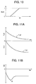
- the turn assist yaw moment generated around the front right wheel first increases along with increase of the braking force, but soon the lateral tire grip force available at the front right wheel starts to decrease due to the limited radius of the friction circle, so that the front right wheel starts to slip toward outside of the turn, thereby canceling the turn assist yaw moment first generated. Therefore, the yaw moment Mfr available for the vehicle body according to Sfr first increases but soon reaches a peak point P and then decreases as shown in Fig. 11B.
- step 552 the factors Wdsfr and Wdsfl are normally set to 1 for convenience.
- step 554 it is judged if the slip angle ⁇ f of the front wheels is positive. (It is the general practice that the slip angle of a wheel is made positive when it is oriented leftward from the direction of rotation thereof, and negative for the direction opposite thereto.)
- the control proceeds to step 556, and it is judged if the nominal yaw moment Mn is negative. Therefore, the yes of the judgment of step 556 means that the vehicle is making a right turn, while the control exerts a clockwise yaw moment to the vehicle body. Under such a condition, if the front right wheel is braked much, there would occur that the yaw moment Mfr is controlled around the peak point P of Fig.
- the weighting factor Wdsfr for ⁇ Sfr is set to 5, i.e. five times as much as compared with those for the other wheels, so that the value of ⁇ Sfr is suppressed low to be apart from the peak point P.
- step 554 when the answer of step 554 is no, and the answer of step 560 is yes, the weighting factor Wdsfl is set to 5.
- step 600 the slip ratios Si are modified by corresponding ⁇ Si calculated.
- step 650 the slip ratio Si is modified for a precaution of a spin which might be induced by the controlled braking of the rear wheels.
- a vehicle is controlled by the running behavior control device of the present invention with one or both of the rear wheels being braked at a controlled slip ratio Srr and/or Srl to assist a turn running of the vehicle, it can occur that the turning of the vehicle overshoots.
- Srr and/or Srl controlled slip ratio
- step 652 it is judged if the nominal yaw moment Mn is negative and the slip ratio ⁇ r is positive and further the yaw rate ⁇ is positive.
- Mn ⁇ 0, ⁇ r > 0 and ⁇ ⁇ 0 it is detected that the conditions turned over from the second stage to the third stage.
- step 654 it is detected that the same turnover occurred during a left turn of the vehicle.
- step 652 When the above turnover was detected in step 652 during a right turn or in step 654 during a left turn, the control proceeds to step 656, and the slip ratios Srr and Srl are immediately returned to zero.
- step 700 the hydraulic circuit 22 is operated according to a control signal bearing the instructions with regard to the slip ratios Si to be realized at the respective wheels.
- the calculations through the main routine of Fig. 2 are repeated at a cycle time such as tens of microseconds as long as the vehicle is operated with the ignition switch being turned on, while the calculations continually converging to each different state according to continual variations of the running conditions of the vehicle, realizing the condition that the braking for the running behavior control is executed at a minimum necessity to follow the tire model which executes no braking.
Landscapes
- Engineering & Computer Science (AREA)
- Transportation (AREA)
- Mechanical Engineering (AREA)
- Chemical & Material Sciences (AREA)
- Combustion & Propulsion (AREA)
- Regulating Braking Force (AREA)
- Hydraulic Control Valves For Brake Systems (AREA)
- Control Of Driving Devices And Active Controlling Of Vehicle (AREA)
Applications Claiming Priority (4)
| Application Number | Priority Date | Filing Date | Title |
|---|---|---|---|
| JP11412698 | 1998-04-09 | ||
| JP11412698 | 1998-04-09 | ||
| JP33265298 | 1998-11-24 | ||
| JP33265298A JP3458734B2 (ja) | 1998-04-09 | 1998-11-24 | 車輌の運動制御装置 |
Publications (3)
| Publication Number | Publication Date |
|---|---|
| EP0949131A2 true EP0949131A2 (de) | 1999-10-13 |
| EP0949131A3 EP0949131A3 (de) | 2000-11-22 |
| EP0949131B1 EP0949131B1 (de) | 2006-11-29 |
Family
ID=26452959
Family Applications (1)
| Application Number | Title | Priority Date | Filing Date |
|---|---|---|---|
| EP99106952A Expired - Lifetime EP0949131B1 (de) | 1998-04-09 | 1999-04-08 | Vorrichtung zur Regelung des Fahrverhaltens eines Kraftfahrzeugs unter Verwendung eines mathematischen Reifenmodells |
Country Status (6)
| Country | Link |
|---|---|
| US (1) | US6308126B2 (de) |
| EP (1) | EP0949131B1 (de) |
| JP (1) | JP3458734B2 (de) |
| CA (1) | CA2266793C (de) |
| DE (1) | DE69934161T2 (de) |
| ES (1) | ES2274594T3 (de) |
Cited By (4)
| Publication number | Priority date | Publication date | Assignee | Title |
|---|---|---|---|---|
| EP1207090A3 (de) * | 2000-11-20 | 2003-01-02 | Toyota Jidosha Kabushiki Kaisha | Vorrichtung und Verfahren zur Regelung der Fahrzeugbewegung |
| EP1396372A2 (de) | 2002-09-04 | 2004-03-10 | Fuji Jukogyo Kabushiki Kaisha | Vorrichtung und Verfahren zur Leistungsregelung in Kurven |
| WO2006100541A1 (en) | 2005-03-24 | 2006-09-28 | Haldex Brake Products Ab | Tire slip model |
| WO2007116279A1 (en) * | 2006-03-31 | 2007-10-18 | Toyota Jidosha Kabushiki Kaisha | Vehicle dynamics control system and method of controlling vehicle dynamics |
Families Citing this family (44)
| Publication number | Priority date | Publication date | Assignee | Title |
|---|---|---|---|---|
| JP2000344077A (ja) | 1999-06-08 | 2000-12-12 | Toyota Motor Corp | 車両の挙動制御装置 |
| DE10116353B4 (de) * | 2000-04-03 | 2006-03-30 | Aisin Seiki K.K., Kariya | Bremskraftverteilungssteuervorrichtung |
| JP2001287632A (ja) * | 2000-04-05 | 2001-10-16 | Toyota Central Res & Dev Lab Inc | 制動力制御装置 |
| JP3960740B2 (ja) | 2000-07-31 | 2007-08-15 | トヨタ自動車株式会社 | 車両の制動制御装置 |
| JP3458839B2 (ja) * | 2000-11-20 | 2003-10-20 | トヨタ自動車株式会社 | 路面の最大摩擦係数推定装置 |
| DE10160049B4 (de) * | 2000-12-30 | 2006-04-27 | Robert Bosch Gmbh | System und Vefahren zur Überwachung des Fahrverhaltens eines Kraftfahrzeugs |
| US8175886B2 (en) | 2001-03-29 | 2012-05-08 | Intellisist, Inc. | Determination of signal-processing approach based on signal destination characteristics |
| US6885735B2 (en) | 2001-03-29 | 2005-04-26 | Intellisist, Llc | System and method for transmitting voice input from a remote location over a wireless data channel |
| US6591168B2 (en) * | 2001-08-31 | 2003-07-08 | Intellisist, Inc. | System and method for adaptable mobile user interface |
| USRE46109E1 (en) | 2001-03-29 | 2016-08-16 | Lg Electronics Inc. | Vehicle navigation system and method |
| US7236777B2 (en) | 2002-05-16 | 2007-06-26 | Intellisist, Inc. | System and method for dynamically configuring wireless network geographic coverage or service levels |
| US6549842B1 (en) * | 2001-10-31 | 2003-04-15 | Delphi Technologies, Inc. | Method and apparatus for determining an individual wheel surface coefficient of adhesion |
| JP4165380B2 (ja) * | 2003-01-31 | 2008-10-15 | 株式会社豊田中央研究所 | 車両制御方法及び車両制御装置 |
| JP3876244B2 (ja) * | 2003-09-19 | 2007-01-31 | 横浜ゴム株式会社 | タイヤのパラメータ値導出方法、タイヤのコーナリング特性算出方法、タイヤの設計方法、車両の運動解析方法およびプログラム |
| JP4268019B2 (ja) | 2003-11-14 | 2009-05-27 | 株式会社豊田中央研究所 | 車体運動実現方法及び装置 |
| US6904351B1 (en) * | 2004-03-17 | 2005-06-07 | Delphi Technologies, Inc. | Operating a vehicle control system |
| JP4029856B2 (ja) * | 2004-03-26 | 2008-01-09 | トヨタ自動車株式会社 | 車輌の挙動制御装置 |
| JP4638185B2 (ja) * | 2004-08-04 | 2011-02-23 | 富士重工業株式会社 | 車両の挙動制御装置 |
| US20060108869A1 (en) * | 2004-11-19 | 2006-05-25 | Continental Teves, Inc. | Electronic stability system-strategy to improve the stability performance in cold temperatures |
| US7966113B2 (en) * | 2005-08-25 | 2011-06-21 | Robert Bosch Gmbh | Vehicle stability control system |
| DE102005046612B4 (de) * | 2005-09-29 | 2019-05-16 | Zf Friedrichshafen Ag | Verfahren zur Realisierung von Fahrdynamikfunktionen unter Verwendung eines echtzeitfähigen Reifenmodells |
| JP4140626B2 (ja) * | 2005-10-07 | 2008-08-27 | トヨタ自動車株式会社 | 車輪接地荷重の変化率に応じて制駆動力制御態様を変更する車輌 |
| US7641014B2 (en) * | 2006-01-31 | 2010-01-05 | Robert Bosch Gmbh | Traction control system and method |
| JP4872386B2 (ja) * | 2006-03-08 | 2012-02-08 | 株式会社アドヴィックス | 車両の運動制御装置 |
| JP4781882B2 (ja) * | 2006-03-31 | 2011-09-28 | 株式会社豊田中央研究所 | 車両運動制御装置及び制御方法 |
| JP5090664B2 (ja) * | 2006-05-11 | 2012-12-05 | 本田技研工業株式会社 | 4輪駆動車の駆動力制御方法 |
| DE102006052624A1 (de) * | 2006-11-08 | 2008-05-15 | Bayerische Motoren Werke Ag | Verfahren zum Ermitteln der von einem Fahrzeugreifen übertragenen Seitenkräfte oder Längskräfte mit einem sogenannten Reifenmodell |
| US20080123284A1 (en) * | 2006-11-29 | 2008-05-29 | Dell Products, Lp | Server rack door mounted display assembly |
| JP4680977B2 (ja) * | 2007-12-18 | 2011-05-11 | 本田技研工業株式会社 | 車両の挙動制御装置 |
| RU2561478C1 (ru) * | 2011-07-20 | 2015-08-27 | Тойота Дзидося Кабусики Кайся | Система управления транспортного средства |
| WO2014187509A1 (en) * | 2013-05-22 | 2014-11-27 | Aktiebolaget Skf | Slip control system for vehicles and a vehicle provided with a slip control system |
| WO2016022331A1 (en) | 2014-08-06 | 2016-02-11 | Bridgestone Americas Tire Operations, Llc | Method of modeling tire performance |
| JP6416574B2 (ja) * | 2014-09-29 | 2018-10-31 | 日立オートモティブシステムズ株式会社 | 車両の制御方法、車両制御システム、車両制御装置、および制御プログラム |
| US9260148B1 (en) * | 2014-11-24 | 2016-02-16 | Wen-Sung Lee | Light unit for bicycle/motorbike |
| CN104590254B (zh) * | 2015-01-15 | 2017-05-17 | 盐城工学院 | 一种汽车转弯防侧翻方法及系统 |
| CN105857304B (zh) * | 2016-05-23 | 2018-11-23 | 武汉理工大学 | 基于四轮驱动汽车力矩分配控制系统 |
| CN106183892B (zh) * | 2016-10-09 | 2018-08-10 | 重庆理工大学 | 电动轮驱动汽车的试验样车及驱动稳定性控制方法 |
| JP6705778B2 (ja) | 2017-07-19 | 2020-06-03 | トヨタ自動車株式会社 | 車両用挙動制御装置 |
| JP6748619B2 (ja) * | 2017-09-20 | 2020-09-02 | 日立オートモティブシステムズ株式会社 | 車両制御装置、車両制御方法および車両制御システム |
| DE102018200180A1 (de) * | 2018-01-08 | 2019-07-11 | Robert Bosch Gmbh | Verfahren zur Ermittlung des Reibwerts zwischen einem Fahrzeugrad und der Fahrbahn |
| CN111114528A (zh) * | 2019-12-11 | 2020-05-08 | 中国航空工业集团公司洛阳电光设备研究所 | 一种应用在独立悬挂式四转四驱智能车的多轴转向驱动方法 |
| EP4001030B1 (de) * | 2020-11-16 | 2024-12-11 | Volvo Truck Corporation | Verfahren zur regelung des radschlupfes eines fahrzeugs |
| US12195046B2 (en) * | 2021-06-30 | 2025-01-14 | Waymo Llc | Handling maneuver limits for autonomous driving systems |
| CN118466469B (zh) * | 2024-07-10 | 2024-09-27 | 中汽智联技术有限公司 | 一种基于dsi3协议的域控制器泊车功能测试系统 |
Family Cites Families (22)
| Publication number | Priority date | Publication date | Assignee | Title |
|---|---|---|---|---|
| DE4026626A1 (de) * | 1990-08-23 | 1992-02-27 | Bosch Gmbh Robert | Verfahren zur regelung der fahrzeugdynamik |
| DE4030704C2 (de) | 1990-09-28 | 2000-01-13 | Bosch Gmbh Robert | Verfahren zur Verbesserung der Beherrschbarkeit von Kraftfahrzeugen beim Bremsen |
| DE4030653A1 (de) * | 1990-09-28 | 1992-04-02 | Bosch Gmbh Robert | Verfahren zum bestimmen der schraeglaufwinkel und/oder der seitenfuehrungskraefte eines gebremsten fahrzeuges |
| US5668724A (en) * | 1990-09-28 | 1997-09-16 | Robert Bosch Gmbh | Method for improving the controllabilty of motor vehicles |
| JP2985287B2 (ja) * | 1990-11-28 | 1999-11-29 | トヨタ自動車株式会社 | 車両制御装置 |
| JP2663712B2 (ja) * | 1990-11-28 | 1997-10-15 | トヨタ自動車株式会社 | 車両制御装置 |
| US5251137A (en) * | 1991-07-10 | 1993-10-05 | General Motors Corporation | Vehicle handling control method for antilock braking |
| US5802491A (en) * | 1992-09-10 | 1998-09-01 | Robert Bosch Gmbh | Motor vehicle control system and method |
| DE4243717A1 (de) * | 1992-12-23 | 1994-06-30 | Bosch Gmbh Robert | Verfahren zur Regelung der Fahrzeugstabilität |
| JP3161206B2 (ja) * | 1994-02-10 | 2001-04-25 | トヨタ自動車株式会社 | 車両の旋回挙動制御装置 |
| JP3047762B2 (ja) * | 1995-01-30 | 2000-06-05 | トヨタ自動車株式会社 | 車両状態推定装置 |
| JP3189610B2 (ja) * | 1995-02-20 | 2001-07-16 | トヨタ自動車株式会社 | 車両挙動制御装置 |
| JP3303605B2 (ja) * | 1995-05-17 | 2002-07-22 | トヨタ自動車株式会社 | 車輌の挙動制御装置 |
| JP3225790B2 (ja) * | 1995-06-09 | 2001-11-05 | トヨタ自動車株式会社 | 車両挙動制御装置 |
| JP3158978B2 (ja) * | 1995-08-08 | 2001-04-23 | トヨタ自動車株式会社 | 車両の挙動制御装置 |
| JP3060923B2 (ja) * | 1995-11-24 | 2000-07-10 | トヨタ自動車株式会社 | 車両状態推定装置 |
| US5899952A (en) | 1995-12-27 | 1999-05-04 | Toyota Jidosha Kabushiki Kaisha | Device for estimating slip angle of vehicle body through interrelation thereof with yaw rate |
| JP3267137B2 (ja) * | 1996-01-16 | 2002-03-18 | トヨタ自動車株式会社 | 車輌の挙動制御装置 |
| JP3470504B2 (ja) | 1996-05-10 | 2003-11-25 | トヨタ自動車株式会社 | 自動変速機の変速制御装置 |
| JP3553735B2 (ja) * | 1996-06-13 | 2004-08-11 | 正人 安部 | 車両挙動制御方法及びその装置 |
| DE59706597D1 (de) * | 1996-09-13 | 2002-04-18 | Volkswagen Ag | Verfahren und Vorrichtung zur Regelung des querdynamischen Verhaltens eines Kraftfahrzeugs |
| DE19650691C2 (de) * | 1996-12-07 | 1998-10-29 | Deutsch Zentr Luft & Raumfahrt | Verfahren zur Lenkunterstützung eines Fahrers eines Straßenfahrzeugs |
-
1998
- 1998-11-24 JP JP33265298A patent/JP3458734B2/ja not_active Expired - Lifetime
-
1999
- 1999-03-31 US US09/282,416 patent/US6308126B2/en not_active Expired - Lifetime
- 1999-04-08 CA CA002266793A patent/CA2266793C/en not_active Expired - Lifetime
- 1999-04-08 EP EP99106952A patent/EP0949131B1/de not_active Expired - Lifetime
- 1999-04-08 DE DE69934161T patent/DE69934161T2/de not_active Expired - Lifetime
- 1999-04-08 ES ES99106952T patent/ES2274594T3/es not_active Expired - Lifetime
Non-Patent Citations (1)
| Title |
|---|
| None |
Cited By (7)
| Publication number | Priority date | Publication date | Assignee | Title |
|---|---|---|---|---|
| EP1207090A3 (de) * | 2000-11-20 | 2003-01-02 | Toyota Jidosha Kabushiki Kaisha | Vorrichtung und Verfahren zur Regelung der Fahrzeugbewegung |
| US6659570B2 (en) | 2000-11-20 | 2003-12-09 | Toyota Jidosha Kabushiki Kaisha | Vehicle motion control device and method |
| KR100489149B1 (ko) * | 2000-11-20 | 2005-05-17 | 도요타지도샤가부시키가이샤 | 차량 운동 제어 장치 및 방법 |
| EP1396372A2 (de) | 2002-09-04 | 2004-03-10 | Fuji Jukogyo Kabushiki Kaisha | Vorrichtung und Verfahren zur Leistungsregelung in Kurven |
| EP1396372A3 (de) * | 2002-09-04 | 2008-03-26 | Fuji Jukogyo Kabushiki Kaisha | Vorrichtung und Verfahren zur Leistungsregelung in Kurven |
| WO2006100541A1 (en) | 2005-03-24 | 2006-09-28 | Haldex Brake Products Ab | Tire slip model |
| WO2007116279A1 (en) * | 2006-03-31 | 2007-10-18 | Toyota Jidosha Kabushiki Kaisha | Vehicle dynamics control system and method of controlling vehicle dynamics |
Also Published As
| Publication number | Publication date |
|---|---|
| JPH11348753A (ja) | 1999-12-21 |
| EP0949131A3 (de) | 2000-11-22 |
| DE69934161T2 (de) | 2007-10-25 |
| DE69934161D1 (de) | 2007-01-11 |
| JP3458734B2 (ja) | 2003-10-20 |
| US20010007965A1 (en) | 2001-07-12 |
| CA2266793A1 (en) | 1999-10-09 |
| US6308126B2 (en) | 2001-10-23 |
| ES2274594T3 (es) | 2007-05-16 |
| EP0949131B1 (de) | 2006-11-29 |
| CA2266793C (en) | 2001-12-04 |
Similar Documents
| Publication | Publication Date | Title |
|---|---|---|
| EP0949131B1 (de) | Vorrichtung zur Regelung des Fahrverhaltens eines Kraftfahrzeugs unter Verwendung eines mathematischen Reifenmodells | |
| US6266601B1 (en) | Device for controlling running behavior of vehicle by mathematical tire model with compensation for brake malfunction | |
| US6473682B2 (en) | Apparatus and method for estimating maximum road friction coefficient | |
| US6178368B1 (en) | Roll control device of vehicles with tracing of turning course | |
| US6564140B2 (en) | Vehicle dynamics control system and vehicle having the vehicle dynamics control system | |
| US6539298B2 (en) | Driving control device and methods for vehicle | |
| JP3546830B2 (ja) | 車輌のロール挙動制御装置 | |
| US6904351B1 (en) | Operating a vehicle control system | |
| WO2020043198A1 (zh) | 一种车辆控制方法及设备 | |
| JP2753793B2 (ja) | 車両における車輪前後力制御方法 | |
| JP2000177556A (ja) | 車輌の運動制御装置 | |
| US20030074122A1 (en) | Dynamic side to side brake proportioning | |
| JP2002211378A (ja) | 車輌の制駆動力制御装置 | |
| CN101189149A (zh) | 车辆制动/驱动力控制设备 | |
| CN106143210B (zh) | 四轮驱动车辆的驱动力控制装置 | |
| CN105774458A (zh) | 用于控制悬架系统的方法 | |
| JP3161206B2 (ja) | 車両の旋回挙動制御装置 | |
| JP2000190832A (ja) | 車輌の運動制御装置 | |
| JP3702779B2 (ja) | 車両の挙動制御装置 | |
| Dreyer et al. | Control strategies for active chassis systems with respect to road friction | |
| JP2004025996A (ja) | 車輌の運動制御装置 | |
| JP2002173012A (ja) | 車輌の挙動制御装置 | |
| US20050029862A1 (en) | Vehicle motion control apparatus | |
| JP3447969B2 (ja) | 車輌の運動制御装置 | |
| JP2000190835A (ja) | 車輌の制動制御装置 |
Legal Events
| Date | Code | Title | Description |
|---|---|---|---|
| PUAI | Public reference made under article 153(3) epc to a published international application that has entered the european phase |
Free format text: ORIGINAL CODE: 0009012 |
|
| 17P | Request for examination filed |
Effective date: 19990408 |
|
| AK | Designated contracting states |
Kind code of ref document: A2 Designated state(s): DE ES IT |
|
| AX | Request for extension of the european patent |
Free format text: AL;LT;LV;MK;RO;SI |
|
| PUAL | Search report despatched |
Free format text: ORIGINAL CODE: 0009013 |
|
| AK | Designated contracting states |
Kind code of ref document: A3 Designated state(s): AT BE CH CY DE DK ES FI FR GB GR IE IT LI LU MC NL PT SE |
|
| AX | Request for extension of the european patent |
Free format text: AL;LT;LV;MK;RO;SI |
|
| AKX | Designation fees paid |
Free format text: DE ES IT |
|
| GRAP | Despatch of communication of intention to grant a patent |
Free format text: ORIGINAL CODE: EPIDOSNIGR1 |
|
| RIN1 | Information on inventor provided before grant (corrected) |
Inventor name: TSUBOI, TOSHIHIRO,C/O TOYOTA JIDOSHA K.K. Inventor name: YOKOYAMA, TATSUAKI,C/O TOYOTA JIDOSHA K.K. |
|
| GRAS | Grant fee paid |
Free format text: ORIGINAL CODE: EPIDOSNIGR3 |
|
| GRAA | (expected) grant |
Free format text: ORIGINAL CODE: 0009210 |
|
| AK | Designated contracting states |
Kind code of ref document: B1 Designated state(s): DE ES IT |
|
| REF | Corresponds to: |
Ref document number: 69934161 Country of ref document: DE Date of ref document: 20070111 Kind code of ref document: P |
|
| REG | Reference to a national code |
Ref country code: ES Ref legal event code: FG2A Ref document number: 2274594 Country of ref document: ES Kind code of ref document: T3 |
|
| PLBE | No opposition filed within time limit |
Free format text: ORIGINAL CODE: 0009261 |
|
| STAA | Information on the status of an ep patent application or granted ep patent |
Free format text: STATUS: NO OPPOSITION FILED WITHIN TIME LIMIT |
|
| 26N | No opposition filed |
Effective date: 20070830 |
|
| REG | Reference to a national code |
Ref country code: DE Ref legal event code: R084 Ref document number: 69934161 Country of ref document: DE Effective date: 20130125 |
|
| PGFP | Annual fee paid to national office [announced via postgrant information from national office to epo] |
Ref country code: ES Payment date: 20180507 Year of fee payment: 20 Ref country code: DE Payment date: 20180327 Year of fee payment: 20 |
|
| PGFP | Annual fee paid to national office [announced via postgrant information from national office to epo] |
Ref country code: IT Payment date: 20180420 Year of fee payment: 20 |
|
| REG | Reference to a national code |
Ref country code: DE Ref legal event code: R071 Ref document number: 69934161 Country of ref document: DE |
|
| REG | Reference to a national code |
Ref country code: ES Ref legal event code: FD2A Effective date: 20210129 |
|
| PG25 | Lapsed in a contracting state [announced via postgrant information from national office to epo] |
Ref country code: ES Free format text: LAPSE BECAUSE OF EXPIRATION OF PROTECTION Effective date: 20190409 |