EP0949197A2 - Methode und Vorrichtung zur Herstellung von hochkonzentriertem Ozongas - Google Patents
Methode und Vorrichtung zur Herstellung von hochkonzentriertem Ozongas Download PDFInfo
- Publication number
- EP0949197A2 EP0949197A2 EP99302544A EP99302544A EP0949197A2 EP 0949197 A2 EP0949197 A2 EP 0949197A2 EP 99302544 A EP99302544 A EP 99302544A EP 99302544 A EP99302544 A EP 99302544A EP 0949197 A2 EP0949197 A2 EP 0949197A2
- Authority
- EP
- European Patent Office
- Prior art keywords
- adsorbing
- ozone
- gas
- generating apparatus
- layers
- Prior art date
- Legal status (The legal status is an assumption and is not a legal conclusion. Google has not performed a legal analysis and makes no representation as to the accuracy of the status listed.)
- Granted
Links
Images





Classifications
-
- C—CHEMISTRY; METALLURGY
- C01—INORGANIC CHEMISTRY
- C01B—NON-METALLIC ELEMENTS; COMPOUNDS THEREOF; METALLOIDS OR COMPOUNDS THEREOF NOT COVERED BY SUBCLASS C01C
- C01B13/00—Oxygen; Ozone; Oxides or hydroxides in general
- C01B13/14—Methods for preparing oxides or hydroxides in general
- C01B13/16—Purification
-
- B—PERFORMING OPERATIONS; TRANSPORTING
- B01—PHYSICAL OR CHEMICAL PROCESSES OR APPARATUS IN GENERAL
- B01D—SEPARATION
- B01D53/00—Separation of gases or vapours; Recovering vapours of volatile solvents from gases; Chemical or biological purification of waste gases, e.g. engine exhaust gases, smoke, fumes, flue gases, aerosols
- B01D53/02—Separation of gases or vapours; Recovering vapours of volatile solvents from gases; Chemical or biological purification of waste gases, e.g. engine exhaust gases, smoke, fumes, flue gases, aerosols by adsorption, e.g. preparative gas chromatography
- B01D53/06—Separation of gases or vapours; Recovering vapours of volatile solvents from gases; Chemical or biological purification of waste gases, e.g. engine exhaust gases, smoke, fumes, flue gases, aerosols by adsorption, e.g. preparative gas chromatography with moving adsorbents, e.g. rotating beds
-
- B—PERFORMING OPERATIONS; TRANSPORTING
- B01—PHYSICAL OR CHEMICAL PROCESSES OR APPARATUS IN GENERAL
- B01D—SEPARATION
- B01D53/00—Separation of gases or vapours; Recovering vapours of volatile solvents from gases; Chemical or biological purification of waste gases, e.g. engine exhaust gases, smoke, fumes, flue gases, aerosols
- B01D53/02—Separation of gases or vapours; Recovering vapours of volatile solvents from gases; Chemical or biological purification of waste gases, e.g. engine exhaust gases, smoke, fumes, flue gases, aerosols by adsorption, e.g. preparative gas chromatography
- B01D53/04—Separation of gases or vapours; Recovering vapours of volatile solvents from gases; Chemical or biological purification of waste gases, e.g. engine exhaust gases, smoke, fumes, flue gases, aerosols by adsorption, e.g. preparative gas chromatography with stationary adsorbents
- B01D53/0407—Constructional details of adsorbing systems
-
- B—PERFORMING OPERATIONS; TRANSPORTING
- B01—PHYSICAL OR CHEMICAL PROCESSES OR APPARATUS IN GENERAL
- B01D—SEPARATION
- B01D53/00—Separation of gases or vapours; Recovering vapours of volatile solvents from gases; Chemical or biological purification of waste gases, e.g. engine exhaust gases, smoke, fumes, flue gases, aerosols
- B01D53/02—Separation of gases or vapours; Recovering vapours of volatile solvents from gases; Chemical or biological purification of waste gases, e.g. engine exhaust gases, smoke, fumes, flue gases, aerosols by adsorption, e.g. preparative gas chromatography
- B01D53/04—Separation of gases or vapours; Recovering vapours of volatile solvents from gases; Chemical or biological purification of waste gases, e.g. engine exhaust gases, smoke, fumes, flue gases, aerosols by adsorption, e.g. preparative gas chromatography with stationary adsorbents
- B01D53/0462—Temperature swing adsorption
-
- B—PERFORMING OPERATIONS; TRANSPORTING
- B01—PHYSICAL OR CHEMICAL PROCESSES OR APPARATUS IN GENERAL
- B01D—SEPARATION
- B01D53/00—Separation of gases or vapours; Recovering vapours of volatile solvents from gases; Chemical or biological purification of waste gases, e.g. engine exhaust gases, smoke, fumes, flue gases, aerosols
- B01D53/02—Separation of gases or vapours; Recovering vapours of volatile solvents from gases; Chemical or biological purification of waste gases, e.g. engine exhaust gases, smoke, fumes, flue gases, aerosols by adsorption, e.g. preparative gas chromatography
- B01D53/04—Separation of gases or vapours; Recovering vapours of volatile solvents from gases; Chemical or biological purification of waste gases, e.g. engine exhaust gases, smoke, fumes, flue gases, aerosols by adsorption, e.g. preparative gas chromatography with stationary adsorbents
- B01D53/047—Pressure swing adsorption
-
- C—CHEMISTRY; METALLURGY
- C01—INORGANIC CHEMISTRY
- C01B—NON-METALLIC ELEMENTS; COMPOUNDS THEREOF; METALLOIDS OR COMPOUNDS THEREOF NOT COVERED BY SUBCLASS C01C
- C01B13/00—Oxygen; Ozone; Oxides or hydroxides in general
- C01B13/10—Preparation of ozone
-
- B—PERFORMING OPERATIONS; TRANSPORTING
- B01—PHYSICAL OR CHEMICAL PROCESSES OR APPARATUS IN GENERAL
- B01D—SEPARATION
- B01D2253/00—Adsorbents used in seperation treatment of gases and vapours
- B01D2253/10—Inorganic adsorbents
- B01D2253/106—Silica or silicates
-
- B—PERFORMING OPERATIONS; TRANSPORTING
- B01—PHYSICAL OR CHEMICAL PROCESSES OR APPARATUS IN GENERAL
- B01D—SEPARATION
- B01D2253/00—Adsorbents used in seperation treatment of gases and vapours
- B01D2253/10—Inorganic adsorbents
- B01D2253/106—Silica or silicates
- B01D2253/108—Zeolites
-
- B—PERFORMING OPERATIONS; TRANSPORTING
- B01—PHYSICAL OR CHEMICAL PROCESSES OR APPARATUS IN GENERAL
- B01D—SEPARATION
- B01D2256/00—Main component in the product gas stream after treatment
- B01D2256/14—Ozone
-
- B—PERFORMING OPERATIONS; TRANSPORTING
- B01—PHYSICAL OR CHEMICAL PROCESSES OR APPARATUS IN GENERAL
- B01D—SEPARATION
- B01D2257/00—Components to be removed
- B01D2257/10—Single element gases other than halogens
- B01D2257/104—Oxygen
-
- B—PERFORMING OPERATIONS; TRANSPORTING
- B01—PHYSICAL OR CHEMICAL PROCESSES OR APPARATUS IN GENERAL
- B01D—SEPARATION
- B01D2259/00—Type of treatment
- B01D2259/40—Further details for adsorption processes and devices
- B01D2259/40011—Methods relating to the process cycle in pressure or temperature swing adsorption
- B01D2259/40043—Purging
- B01D2259/4005—Nature of purge gas
- B01D2259/40056—Gases other than recycled product or process gas
-
- B—PERFORMING OPERATIONS; TRANSPORTING
- B01—PHYSICAL OR CHEMICAL PROCESSES OR APPARATUS IN GENERAL
- B01D—SEPARATION
- B01D2259/00—Type of treatment
- B01D2259/40—Further details for adsorption processes and devices
- B01D2259/402—Further details for adsorption processes and devices using two beds
-
- B—PERFORMING OPERATIONS; TRANSPORTING
- B01—PHYSICAL OR CHEMICAL PROCESSES OR APPARATUS IN GENERAL
- B01D—SEPARATION
- B01D53/00—Separation of gases or vapours; Recovering vapours of volatile solvents from gases; Chemical or biological purification of waste gases, e.g. engine exhaust gases, smoke, fumes, flue gases, aerosols
- B01D53/02—Separation of gases or vapours; Recovering vapours of volatile solvents from gases; Chemical or biological purification of waste gases, e.g. engine exhaust gases, smoke, fumes, flue gases, aerosols by adsorption, e.g. preparative gas chromatography
Definitions
- the present invention relates to a manufacturing method of high concentration ozone gas and an apparatus thereof using a pressure swing adsorption apparatus (PSA apparatus) having plural adsorbing layers filled with a specific high silica ozone adsorbent large in the difference of ozone adsorbing amount between adsorption pressure and desorption pressure, that is, the ozone adsorbing capability.
- PSA apparatus pressure swing adsorption apparatus
- the invention also relates to a manufacturing method of high concentration ozone gas and an apparatus thereof for concentrating ozone by a temperature swing adsorption system for changing over an ozone adsorbing process at a relatively low temperature and an ozone recovery process at a relatively high temperature, by using a specific ozone adsorbent having a high ozone adsorbing capability even in the presence of water.
- Ozone is produced by using silent discharge apparatus or water electrolytic apparatus, but the ozone gas obtained from these apparatuses are low in concentration, and it is usually used after concentrating by an ozone adsorbing apparatus or the like.
- This liquid oxygen 31 is fed into an ozone generating apparatus 32, and the gas containing the ozone is cooled to about -60° C by a heat exchanger 33 and a refrigerating machine 34, it is further fed into an ozone adsorbing tower 35 filled with silica gel to adsorb ozone, the gas containing oxygen flowing out from the adsorbing tower 35 is fed into the heat exchanger 33 to cool the gas containing the ozone, and it is returned to the material side of the ozone generating apparatus 32.
- the adsorbing tower 35 having adsorbed the ozone is transferred to the desorbing process, and the air 37 dried by a dryer 36 is heated by a heat exchanger 38, and is fed into the ozone adsorbing tower 35 to be heated, purged and desorbed, and a concentrated ozone gas 37 is recovered, while the desorbed concentrated ozone gas 39 is fed into the heat exchanger 38, and the dried air is heated. Consequently, the regenerated adsorbing tower 35 by desorbing the ozone is transferred from the desorbing process to the adsorbing process.
- the silica gel is known as ozone adsorbent, but since it is extremely large in the moisture adsorbing capability as compared with ozone, if moisture is present in the gas contacting with the adsorbent (the gas to be treated, purge gas, and the like), the moisture is preferentially adsorbed by the silica gel, and it is hard to desorb the once adsorbed moisture, and the moisture is accumulated, and hence it is difficult to maintain a specific ozone adsorbing capability. As a result, an extremely large amount of silica gel is needed for maintaining a specific gas treating capacity, and the adsorbing apparatus itself is increased in its size. Besides, when adsorption and desorption of moisture are repeated, the silica gel is powdered and may be lowered in the adsorbing capability.
- the ozone adsorbing amount is larger as the temperature is lower, but it is hard to cool lower than -60° C unless a particular refrigerating machine is used, and a large amount of adsorbent is usually required for increasing the treated gas amount, and the apparatus becomes larger in size, which causes to increase the manufacturing cost and running cost of the apparatus.
- the invention of a first group succeeded in solving the above problems by employing the following constitution.
- the invention of the first group can efficiently concentrate the ozone even in the presence of moisture, and thereby the manufacturing apparatus of high concentration ozone gas is reduced in size, and the manufacturing cost and running cost of the apparatus are substantially reduced.
- the silent discharge ozone generating apparatus of high pressure or water electrolytic ozone generating apparatus of high pressure matching with the pressure swing adsorbing apparatus is enhanced, and moreover by feeding the concentrated oxygen gas in the adsorbing process into the hydrogen electrode of the water electrolytic ozone generating apparatus, the oxygen depolarizing action is promoted, and the power to be applied can be decreased.
- the invention of the second group can efficiently concentrate the oxygen even in the presence of moisture, and thereby the manufacturing apparatus of high concentration ozone gas is reduced in size, and the manufacturing cost and running cost of the apparatus are substantially reduced. Moreover, by feeding the concentrated oxygen gas flowing out from the adsorbing process into the hydrogen electrode of the water electrolytic ozone generating apparatus, the oxygen depolarizing action is promoted, and the power to be applied can be decreased. Besides, by returning the concentrated oxygen gas flowing out from the adsorbing process to the oxygen material side of the silent discharge ozone generating apparatus, the concentrated oxygen can be utilized effectively.
- high silica ozone adsorbents in particular, high silica pentasyl zeolite, dealuminized fogersite such as ultra-stable Y type zeolite (USY), and mesoporous silicate such as MCM-41, FSM-16, low temperature acidic synthetic mesoporous silicate having tetra ethoxy silane as silica source and low temperature acidic synthetic mesoporous silicate having low molecular silicic acid as silica source, have an excellent ozone adsorbing capability even in the presence of moisture, and attempted to apply them in the pressure swing adsorbing apparatus for concentrating ozone and succeeded in manufacturing high concentration ozone gas efficiently, thereby enabling to reduce the size of the manufacturing apparatus of high concentration ozone gas, and substantially reduce the manufacturing cost and running cost of the apparatus.
- high silica ozone adsorbents in particular, high silica pentasyl zeolite, dealumin
- the high silica pentasyl zeolite used in the invention has an excellent ozone adsorbing capability, and it can be obtained by hydrothermal synthesis at 150 to 180° C, by using sodium silicate or fumed silica as silica source, and tetrapropyl ammonium bromide as organic template.
- the high silica pentasyl zeolite of the present invention is preferred to have the SiO 2 /Al 2 O 3 ratio of 70 or more, preferably 100 or more.
- the dealuminized fogersite used in the present invention has an excellent ozone adsorbing capability even in the presence of moisture, and by treating Na-Y type zeolite having the SiO 2 /Al 2 O 3 ratio of about 5 in ammonia water, it can be manufactured by removing the majority of Al of the zeolite skeleton.
- the dealuminized fogersite of the present invention is preferred to have the SiO 2 /Al 2 O 3 ratio of 20 or more, preferably 50 or more.
- the mesoporous silicate used in the present invention is a porous substance of silica compound having meso pores of 10 to 1000 ⁇ , and has an excellent ozone adsorbing capability even in the presence of moisture.
- the mesoporous silicate of the present invention can be manufactured in various methods, and its SiO 2 /Al 2 O 3 ratio is preferred to be 20 or more, preferably 50 or more.
- the mesoporous silicate itself has been known as mentioned below, it was first discovered by the present inventors that it has such ozone adsorbing capability as mentioned above.
- MCM-41 was developed by Mobil, which is a mesoporous silicate with the specific surface area of about 1600 m 2 /g and SiO 2 /Al 2 O 3 ratio of about 1000, obtained by hydrothermal synthesis at temperature of 140°C and pH 13.5, by using water glass or sodium silicate as silica source, and cationic surface active agent (with 8 or more carbon atoms) as organic template.
- FSM-16 is a mesoporous silicate with the SiO 2 /Al 2 O 3 ratio of about 1000 obtained by intercalation of cationic surface active agent in Kanemite developed by Kuroda, Inada, et al., and has a structure similar to that of MCM-41.
- Low temperature mesoporous silicate (1) is obtained by a method proposed by Stucky et al., and is synthesized at pH 1 or less at room temperature, using tetraethoxy silane (TEOS) as silica source and cationic surface active agent as organic template.
- Low temperature mesoporous silicate (2) is obtained by a method developed by the present inventors, and is synthesized at pH 1 or less at room temperature, using condensation-polymerized silica-free silicic acid as silica source and cationic surface active agent as organic template.
- These low temperature mesoporous silicates may be manufactured in a wide range, depending on the manufacturing conditions, ranging from the SiO 2 /Al 2 O 3 ratio of 10 to a substantially SiO2 only compound.
- the invention of a first group provides a method and apparatus for manufacturing high concentration ozone gas characterized by manufacturing gas containing ozone by an ozone generating apparatus such as silent discharge apparatus or water electrolytic apparatus, using plural adsorbing layers filled with specific high silica ozone adsorbent, adsorbing ozone by feeding the gas containing ozone into the adsorbing layers in an adsorbing process at a relatively high pressure, while desorbing ozone by setting the adsorbing layers in a desorbing process at a relatively low pressure, feeding purge gas in the desorbing process if necessary, and employing a pressure swing adsorbing system for alternately changing over the adsorbing layers between the adsorbing process at a relatively high pressure and the desorbing process at a relatively low pressure in a short time, thereby concentrating the ozone.
- the gas containing ozone flowing out from the silent discharge apparatus can be recovered at high pressure, and the load of the compressor for feeding to the pressure swing adsorbing apparatus can be reduced.
- the oxygen material gas to be supplied into the silent discharge ozone generating apparatus the high pressure oxygen concentrated gas manufactured in the pressure swing adsorbing apparatus for concentrating oxygen can be used, which is effective for efficiency and performance of the entire apparatus.
- the adsorbing tower transferred to the desorbing process of the pressure swing adsorbing apparatus for concentrating ozone recovers ozone concentrated gas by setting to a relatively low desorbing pressure by using, for example, a decompression pump, but it is also possible to promote desorption by purging by feeding part of the high pressure oxygen concentrated gas flowing out from the desorbing process into the adsorbing layers in the desorbing process through a reducing valve.
- a heat exchanger or a heater may be attached to the downstream side of the reducing valve to heat the oxygen concentrated gas to a temperature suited to purging.
- Fig. 1 is a conceptual diagram of a manufacturing apparatus of high concentration ozone combining a water electrolytic ozone generating apparatus 1 of high pressure, and a two-tower type pressure swing adsorbing apparatus for concentrating ozone.
- Adsorbing towers 6 and 7 are filled with ozone adsorbent of one or two or more kinds of adsorbent selected from the group consisting of high silica pentasyl zeolite, dealuminized fogersite, and mesoporous silicate.
- the water electrolytic ozone generating apparatus 1 consists of an ozone electrode chamber 3 such as PbO 2 , and a hydrogen electrode chamber 4 such as Pt, with an ion exchange film 2 placed between them, and by connecting a direct-current power source 5, electrons are supplied, and ozone is generated in the ozone electrode chamber 3 while hydrogen is generated in the hydrogen electrode chamber 4.
- Fig. 1 shows the state of holding the adsorbing tower 6 in an adsorbing process and the adsorbing tower 7 in a desorbing process, by opening changeover valves 10, 13, 17, 21, and closing changeover valves 11, 14, 16, 20, and by opening and closing the changeover valves reversely, the process can be changed over from absorption to desorption, and from desorption to adsorption.
- the gas containing ozone from the ozone generating apparatus 1 is pressurized to an adsorbing pressure by a compressor 9 provided on a lead pipe 8, and is supplied into the adsorbing tower 6 in the adsorbing process to adsorb ozone on the adsorbent, and the oxygen concentrated gas flowing out from the adsorbing tower 6 is supplied into the hydrogen electrode chamber 4 of the water electrolytic ozone generating apparatus 1 through a lead pipe 12, and the power consumption of the ozone generating apparatus is saved by the oxygen depolarizing action.
- the ozone recovering system is held at a desorbing pressure, and by opening the changeover valve 17 of a lead pipe 15, ozone is recovered by decompressed desorption from the adsorbing tower 7 in the desorbing process.
- Part of the high pressure oxygen concentrated gas flowing out from the adsorbing tower 6 in the desorbing process is reduced to a desorbing pressure by a reducing valve 19 provided in a lead pipe 18 for feeding purge gas branched off from the lead pipe 12, and supplied into the adsorbing tower 7 in the desorbing process to purge by back wash, so that the desorption may be promoted.
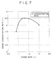
- the purge rate is preferably in a range of 1 to 2, more preferably in a range of 1.2 to 1.5 (see Fig. 7).
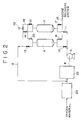
- Fig. 2 is a conceptual diagram of a manufacturing apparatus of high concentration ozone using a silent discharge ozone generating apparatus 22 of high pressure, instead of the water electrolytic ozone generating apparatus of high pressure in the manufacturing apparatus of high concentration ozone in Fig. 1, and the structure of the pressure swing adsorbing apparatus is same as in the apparatus in Fig. 1, and the reference numerals of the apparatus are hence matched.
- a pressure swing adsorbing apparatus 23 for concentration oxygen is attached before the silent discharge ozone generating apparatus 22.
- This pressure swing adsorbing apparatus 23 for concentrating oxygen is not essential, but is effective for enhancing the efficiency and performance of the entire apparatus.
- the adsorption cycle of the pressure swing adsorbing apparatus for concentrating ozone is same as in the case of Fig. 1, but part of the high pressure oxygen concentrated gas flowing out from the adsorbing tower 6 in the adsorbing process is, if necessary, returned to the lead pipe for feeding oxygen material of the silent discharge ozone generating apparatus 22 through the lead pipe 12, so that the oxygen concentrated gas can be used effectively. Furthermore, by using the silent discharge ozone generating apparatus of high pressure, the load of the compressor 9 for feeding gas containing ozone to the pressure swing adsorbing apparatus can be reduced, and it is effective for enhancing the efficiency and performance of the entire apparatus.
- the invention of a second group provides a method and apparatus for manufacturing high concentration ozone gas, characterized by using two or more adsorbing layers filled with ozone adsorbent, employing a temperature swing adsorbing system for transferring the adsorbing layers from an adsorbing process at a relatively low temperature to a desorbing process at a relatively high temperature, and further returning to the adsorbing process, precooling gas containing ozone from an ozone generating apparatus and feeding into the adsorbing layers in the adsorbing process, discharging oxygen concentrated gas at a relatively low temperature from the adsorbing layers, passing purge gas at a relatively high temperature into the adsorbing layers in the desorbing process in an opposite direction of the gas flow in the adsorbing process, and recovering the concentrated ozone gas continuously, in which the ozone adsorbent is a specific high silica ozone adsorbent excellent in ozone adsorbing capability
- the cooling energy effectively by cooling the gas containing ozone from the ozone generating apparatus by oxygen concentrated gas at a relatively low temperature flowing out from the adsorption process of the temperature swing adsorbing apparatus for concentrating ozone.
- a silent discharge apparatus as the ozone generating apparatus, it is preferred to utilize the oxygen effectively by returning the oxygen concentrated gas at a relatively low temperature flowing out from the adsorbing process of the temperature swing adsorbing apparatus for concentrating ozone to the oxygen material side of the silent discharge ozone generating apparatus.
- Fig. 8 is a conceptual diagram of a manufacturing apparatus of high concentration ozone combining a water electrolytic ozone generating apparatus 101, and a two-tower type temperature swing adsorbing apparatus for concentrating ozone.
- Adsorbing towers 108 and 109 are filled with ozone adsorbent of one or two or more kinds of adsorbent selected from the group consisting of high silica pentasyl zeolite, dealuminized fogersite, and mesoporous silicate.
- the ozone adsorbent may be used also by forming in a honeycomb structure.
- the water electrolytic ozone generating apparatus 101 consists of an ozone electrode chamber 103 such as PbO 2 , and a hydrogen electrode chamber 104 such as Pt, with an ion exchange film 102 placed between them, and by connecting a direct-current power source 105, electrons are supplied, and ozone is generated in the ozone electrode chamber 103 while hydrogen is generated in the hydrogen electrode chamber 104.
- the adsorbing tower 108 is set in an adsorbing process and the adsorbing tower 109 in a desorbing process, and by opening and closing the changeover valves reversely after the processes, the adsorbing tower 108 is transferred from absorption process to desorption process, and the adsorbing tower 109, from desorption process to adsorption process.
- a heat exchanger 112 and a cooler 111 are attached to a lead pipe 110 for feeding gas containing ozone for connecting the ozone electrode chamber 103 and adsorbing tower 108 of the water electrolytic ozone generating apparatus 101, and the gas containing ozone is cooled to an adsorbing temperature, and is supplied into the adsorbing tower 108 in the adsorbing process to adsorb ozone, and the oxygen concentrated gas at a relatively low temperature flowing out from the adsorbing tower 108 is sent into the heat exchanger 112 through a lead pipe 115 to precool the gas containing ozone.
- Reference numeral 106 is a lead pipe for feeding water
- 107 is a lead pipe for discharging hydrogen from the hydrogen electrode chamber.
- Reference numeral 105 is a direct-current power source.
- part of the oxygen concentrated gas at a relatively low temperature flowing out from the adsorbing tower 108 is supplied into the adsorbing tower 109 in the desorbing process to heat, purge and desorb the ozone through a lead pipe 118 and, if necessary, a reducing valve 119 and a heater 120, and high concentration ozone gas is recovered from a lead pipe 123.
- the purge rate is preferably in a range of 1 to 2.
- the purge gas instead of the oxygen concentrated gas, nitrogen, dry air, argon , helium or the like may be used, and supplied from outside.
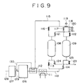
- Fig. 9 is a conceptual diagram of a manufacturing apparatus of high concentration ozone using a silent discharge ozone generating apparatus 126, instead of the water electrolytic ozone generating apparatus in the manufacturing apparatus of high concentration ozone in Fig. 8.
- the parts common to the apparatus in Fig. 8 are identified with same reference numerals.
- a temperature swing adsorbing apparatus 127 for concentration oxygen is attached before the silent discharge ozone generating apparatus 126, but this adsorbing apparatus is not essential. However, considering matching of the entire apparatus, it is preferred to employ it.
- the apparatus in Fig. 9 is a conceptual diagram of a manufacturing apparatus of high concentration ozone using a silent discharge ozone generating apparatus 126, instead of the water electrolytic ozone generating apparatus in the manufacturing apparatus of high concentration ozone in Fig. 8.
- the parts common to the apparatus in Fig. 8 are identified with same reference numerals.
- a temperature swing adsorbing apparatus 127 for concentration oxygen is attached before the silent discharge
- oxygen material for example, air is supplied into the temperature swing adsorbing apparatus 127 for concentrating oxygen through a lead pipe 128, and the concentrated oxygen gas is discharged from a lead pipe 129, and is supplied into the silent discharge ozone generating apparatus 126.
- the adsorption cycle of the temperature swing adsorbing apparatus for concentrating ozone is same as in the case of Fig. 8, but part of the oxygen concentrated gas flowing out from the adsorbing tower in the adsorbing process is preferred to be returned to the oxygen material side of the silent discharge ozone generating apparatus 126 through a lead pipe 130 by way of the heat exchanger 112 for precooling the gas containing ozone, so that the oxygen can be utilized effectively.
- Fig. 10 is a conceptual diagram of a manufacturing apparatus of high concentration ozone combining a water electrolytic ozone generating apparatus 101 and a merry-go-round type temperature swing adsorbing apparatus for concentrating ozone consisting of adsorbing layers 131 to 134.
- the adsorbing layers 131 and 132 are in an adsorbing process, the adsorbing layer 133 in a desorbing process, and the adsorbing layer 134 in a cooling process following the desorbing process.
- the adsorbing layers may be further divided depending on the necessity, and plural adsorbing layers may be used according to the cycle time of each process.
- the merry-go-round of the adsorbing layers is rotated in the arrow direction, and the processes can be transferred sequentially without using changeover valve.
- the gas containing ozone generated in the ozone electrode chamber 103 of the water electrolytic ozone generating apparatus 101 is cooled to an adsorbing temperature by the heat exchanger 112 and cooler 111 of the lead pipe 110, and is supplied into the adsorbing layers 131 and 132 in the adsorbing process to adsorb ozone, and the oxygen concentrated gas at a relatively low temperature flowing out from these adsorbing layers is supplied into the heat exchanger through lead pipes 137, 138, 139, and 140, and further into the hydrogen electrode chamber 104 of the water electrolytic ozone generating apparatus 101, thereby depolarizing the oxygen.
- Part of oxygen concentrated gas at a relatively low temperature flowing out from the adsorbing layers 131 and 132 in the adsorbing process is supplied into the adsorbing layer 134 in the cooling process through a lead pipe 141 branched off from the lead pipe 139, and cools the adsorbing layer 134 after finishing the desorbing process.
- a heater 143 is attached to a lead pipe 142, and after heating to a desorbing temperature, it is supplied into the adsorbing layer 133 in the desorbing process to heat, purge and desorb.
- the purge gas is supplied from a lead pipe 144, and after heating to a desorbing temperature by a heater 145, it is similarly supplied into the adsorbing layer 133, and the desorbed high concentration ozone gas is sent into the recovery system through a lead pipe 146.
- Fig. 11 is similar to the manufacturing apparatus of high concentration ozone in Fig. 10, using a silent discharge ozone generating apparatus 126, instead of the water electrolytic ozone generating apparatus, and the parts common to the apparatus in Fig. 10 are identified with same reference numerals.
- a silent discharge ozone generating apparatus 126 instead of the water electrolytic ozone generating apparatus, and the parts common to the apparatus in Fig. 10 are identified with same reference numerals.
- the apparatus in Fig. 11 is similar to the manufacturing apparatus of high concentration ozone in Fig. 10, using a silent discharge ozone generating apparatus 126, instead of the water electrolytic ozone generating apparatus, and the parts common to the apparatus in Fig. 10 are identified with same reference numerals.
- the apparatus in Fig. 11 is similar to the manufacturing apparatus of high concentration ozone in Fig. 10, using a silent discharge ozone generating apparatus 126, instead of the water electrolytic ozone generating apparatus, and the parts common to the apparatus in Fig
- a temperature swing adsorbing apparatus 127 for concentrating oxygen is attached before the silent discharge ozone generating apparatus 126, and oxygen material, for example, air is supplied into the temperature swing adsorbing apparatus 127 for concentrating oxygen through a lead pipe 128 to concentrate the oxygen, and is supplied into the silent discharge ozone generating apparatus 126 through a lead pipe 129, but in the invention, the temperature swing adsorbing apparatus 127 for concentrating oxygen is not essential.
- the adsorbing operation of the merry-go-round type temperature swing adsorbing apparatus for concentrating ozone is same as in the apparatus in Fig. 10.
- the oxygen concentrated gas at a relatively low temperature flowing out from the adsorbing layers 131 and 132 in the adsorbing process precools, same as in the apparatus shown in Fig. 10, the gas containing ozone by the heat exchanger 112, and is returned to the oxygen material side of the silent discharge ozone generating apparatus 126 through a lead pipe 130, so that the concentrated oxygen gas can be utilized effectively.
- the adsorbing towers of the manufacturing apparatus of high concentration ozone in Fig. 1 were filled with the ozone adsorbents according to the present invention, that is, high silica pentasyl zeolite, dealuminized fogersite, and mesoporous silicate, and a conventional ozone adsorbent, silica gel, and the ozone concentration rate were measured, and the ozone adsorbing capabilities were compared.
- the ozone adsorbents according to the present invention that is, high silica pentasyl zeolite, dealuminized fogersite, and mesoporous silicate
- a conventional ozone adsorbent, silica gel, and the ozone concentration rate were measured, and the ozone adsorbing capabilities were compared.
- the adsorbing towers were filled with 5 kg each of the high silica pentasyl zeolite with the SiO 2 /Al 2 O 3 ratio of 100, dealuminized fogersite with the SiO 2 /Al 2 O 3 ratio of 70, mesoporous silicate with the SiO 2 /Al 2 O 3 ratio of 1000, and commercial silica gel.
- ozone gas (ozone concentration 10%) composed of 10 vol.% of O 3 , 87 vol.% of O 2 , and 3 vol.% of H 2 O was generated, and pressurized to 1.1 atm by a compressor, and supplied into the adsorbing tower in the adsorbing process at a gas flow rate of 15 m 3 N/h, and ozone was adsorbed.
- the adsorbing tower in the desorbing process was decompressed by 0.1 atm by a decompression pump, and the ozone was desorbed and recovered without purging.
- the adsorbing temperature was set at -60° C, -30° C and 25° C, and the ozone concentration was experimented.
- the temperature of the adsorbing tower was not particularly controlled.
- the changeover time of the adsorbing process and desorbing process, that is, the cycle time was set at 3 minutes.
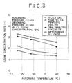
- the ozone concentration of the obtained ozone concentrated gas was measured, and compared with the ozone concentration of the gas produced in the water electrolytic ozone generating apparatus, and the ozone concentration rate was determined, and the adsorbing temperature and the ozone concentration rate are comparatively shown in Fig. 3.
- Fig. 3 As clear from this diagram, as compared with the silica gel, it is known that the dealuminized fogersite and mesoporous silicate show a very large ozone adsorbing capability. Incidentally, the small ozone adsorbing capability of silica gel seems to be due to the effect of moisture in the gas containing ozone.
- the adsorbing temperature is preferred to be set at -60° C or higher, and also considering the use of recovered ozone gas, the adsorbing temperature is preferred to be set at room temperature of 25° C or less.
- the treating capacity of gas containing ozone was investigated (m 3 N/h/1 ton of adsorbent).
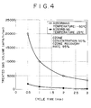
- the adsorbing temperature was set at -60° C and 25° C, the adsorbing pressure was changed to 1.05 atm, and the desorbing pressure to 0.05 atm, and the ozone concentration was experimented same as in Example 1 in all other conditions. Results are shown in Fig. 4.
- the ozone concentration of the gas containing ozone from the water electrolytic ozone generating apparatus was 10 vol.%, but the ozone concentration of the gas recovered in the desorbing process was 50 vol.% (ozone concentration rate 5), and the ozone recovery rate was 95%.
- the treating capacity is larger as the adsorbing temperature is lower and the cycle time is shorter, and a specified treating capacity is obtained by a relatively small amount of adsorbent, and hence it is easy to reduce the size of the adsorbing tower, but a larger cooling energy is required.
- the treating capacity is smaller, but less cooling energy is needed. Near the room temperature, moreover, the effect of cycle time is smaller.
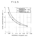
- Example 2 Using the mesoporous silicate same as in Example 2, and changing the desorbing pressure from 0.04 atm to 0.3 atom, the ozone concentration rate was investigated, and the dependence of desorbing pressure was studied.
- the ozone concentration was experimented same as in Example 1, except that the adsorbing temperature was set at -60° C and 25° C and that the adsorbing pressure was fixed at 1.05 atm. Results are shown in Fig. 5.
- the ozone concentration rate elevated almost proportionally as the adsorbing pressure climbed up, and between the adsorbing temperature of -60° C and 25° C, the former was higher in the ozone concentration rate by about 0.5 times.
- the preferred adsorbing pressure was set in a range of 1.05 to 5 atm.
- the ozone concentration rate was investigated and the dependence of purge rate was studied, by fixing the adsorbing pressure at 1.05 atm and the desorbing pressure at 0.05 atm, setting the adsorbing temperature at 25° C, not particularly controlling the temperature of the adsorbing tower in the desorbing process, feeding part of oxygen concentrated gas flowing out from the adsorbing tower in the adsorbing process as purge gas into the adsorbing tower in the desorbing process through a reducing valve, adjusting the reducing valve and changing the purge rate in a range of 0.9 to 2. Results are shown in Fig. 7.
- the ozone concentration rate can be heightened, but as the purge gas volume is increased, the ozone concentration in the recovered gas declines.
- the adsorbing towers of the manufacturing apparatus of high concentration ozone in Fig. 8 were filled with the ozone adsorbents of the present invention, that is, high silica pentasyl zeolite, dealuminized fogersite, and mesoporous silicate, and a conventional ozone adsorbent, silica gel, and the ozone concentration rate were measured, and the ozone adsorbing capabilities were compared.
- the adsorbing towers were filled with 5 kg each of the high silica pentasyl zeolite with the SiO 2 /Al 2 O 3 ratio of 100, dealuminized fogersite with the SiO 2 /Al 2 O 3 ratio of 70, mesoporous silicate with the SiO 2 /Al 2 O 3 ratio of 1000, and commercial silica gel.
- gas containing 10 vol.% of O 3 , 87 vol.% of O 2 , and 3 vol.% of H 2 O (ozone concentration 10%) was generated, and precooled by heat exchange with the oxygen concentrated gas at a relatively low temperature flowing out from the adsorbing tower in the adsorbing process, and then cooled to an adsorbing temperature by a cooler, and supplied into the adsorbing tower in the adsorbing process at a gas flow rate of 15 m 3 N/h, and ozone was adsorbed.
- part of oxygen concentrated gas flowing out from the adsorbing tower in the adsorbing process was heated to a desorbing temperature of 25° C, purge gas was passed in opposite direction of the gas flow in the adsorbing process, and the ozone was heated, purged, desorbed, and recovered.
- the adsorbing temperature was set at -30° C, -50° C and -100° C, and the ozone concentration was experimented.
- the changeover time of the adsorbing process and desorbing process, that is, the cycle time was set at 30 minutes, and the purge rate was set at about 1.5 by using a regulating valve.
- the adsorbing pressure and desorbing pressure were not particularly adjusted, and were about 1.05 atm.
- the ozone concentration of the obtained ozone concentrated gas was measured, and compared with the ozone concentration of the gas produced in the water electrolytic ozone generating apparatus, and the ozone concentration rate was determined, and the adsorbing temperature and the ozone concentration rate are comparatively shown in Fig. 12.
- the dealuminized fogersite and mesoporous silicate show a very large ozone adsorbing capability.
- the small ozone adsorbing capability of silica gel seems to be due to the effect of moisture in the gas containing ozone.
- the adsorbing temperature may be selected in a range of -100 to -30° C, but considering the capacity of cooler for general use, the adsorbing temperature is preferred to be set at -60° C or higher temperature.
- the treating amount of gas containing ozone was investigated (m 3 N/h/1 ton of adsorbent).
- the ozone concentration was experimented same as in Example 6 except that the adsorbing temperature was set at -60° C and -30° C. Results are shown in Fig. 13.
- the ozone concentration of the gas containing ozone from the water electrolytic ozone generating apparatus was 10 vol.%, but the ozone concentration of the gas recovered in the desorbing process was 50 vol.% (ozone concentration rate 5), and the ozone recovery rate was 95%.
- the treating amount is larger as the adsorbing temperature is lower and the cycle time is shorter, and a specified treating amount is obtained by a relatively small amount of adsorbent, and hence it is easy to reduce the size of the adsorbing tower, but a larger cooling energy is required.
- Example 14 Using the mesoporous silicate same as in Example 7, and changing the desorbing temperature from 0° C to 75° C, the ozone concentration rate was investigated, and the dependence of desorbing temperature was studied. In this experiment, too, using the same apparatus in Fig. 8 as in Example 6, the ozone concentration was experimented same as in Example 6, except that the adsorbing temperature was set at -60° C and -30° C. Results are shown in Fig. 14.
Landscapes
- Chemical & Material Sciences (AREA)
- Engineering & Computer Science (AREA)
- Analytical Chemistry (AREA)
- General Chemical & Material Sciences (AREA)
- Oil, Petroleum & Natural Gas (AREA)
- Chemical Kinetics & Catalysis (AREA)
- Organic Chemistry (AREA)
- Inorganic Chemistry (AREA)
- Oxygen, Ozone, And Oxides In General (AREA)
- Separation Of Gases By Adsorption (AREA)
- Solid-Sorbent Or Filter-Aiding Compositions (AREA)
Applications Claiming Priority (4)
| Application Number | Priority Date | Filing Date | Title |
|---|---|---|---|
| JP9014198 | 1998-04-02 | ||
| JP09014198A JP3697056B2 (ja) | 1998-04-02 | 1998-04-02 | 高濃度オゾンガスの製造方法及びその装置 |
| JP09181398A JP3697058B2 (ja) | 1998-04-03 | 1998-04-03 | 高濃度オゾンガスの製造方法及びその装置 |
| JP9181398 | 1998-04-03 |
Publications (3)
| Publication Number | Publication Date |
|---|---|
| EP0949197A2 true EP0949197A2 (de) | 1999-10-13 |
| EP0949197A3 EP0949197A3 (de) | 2001-03-07 |
| EP0949197B1 EP0949197B1 (de) | 2006-11-15 |
Family
ID=26431647
Family Applications (1)
| Application Number | Title | Priority Date | Filing Date |
|---|---|---|---|
| EP99302544A Expired - Lifetime EP0949197B1 (de) | 1998-04-02 | 1999-03-31 | Methode und Vorrichtung zur Herstellung von hochkonzentriertem Ozongas |
Country Status (8)
| Country | Link |
|---|---|
| US (2) | US6254763B1 (de) |
| EP (1) | EP0949197B1 (de) |
| KR (1) | KR100307344B1 (de) |
| AT (1) | ATE345314T1 (de) |
| AU (1) | AU750512B2 (de) |
| CA (1) | CA2267938C (de) |
| DE (1) | DE69933965D1 (de) |
| NO (1) | NO329817B1 (de) |
Cited By (2)
| Publication number | Priority date | Publication date | Assignee | Title |
|---|---|---|---|---|
| EP1101732A1 (de) * | 1998-05-22 | 2001-05-23 | Iwatani Sangyo Kabushiki Kaisha( Iwatani International Corporation) | Verfahren und Vorrichtung zur kontinuierlichen Erzeugung von hochkonzentriertem Ozongas |
| CN111111581A (zh) * | 2019-12-19 | 2020-05-08 | 中国科学院电工研究所 | 一种等离子体燃料重整装置 |
Families Citing this family (28)
| Publication number | Priority date | Publication date | Assignee | Title |
|---|---|---|---|---|
| JP2001248794A (ja) * | 2000-03-02 | 2001-09-14 | Kansai Electric Power Co Inc:The | オゾン貯蔵方法および装置 |
| US6916359B2 (en) * | 2002-04-25 | 2005-07-12 | The Boc Group, Inc. | Ozone production processes |
| US7392657B2 (en) * | 2004-06-09 | 2008-07-01 | American Air Liquide, Inc. | Methods of dissolving ozone in a cryogen |
| CN100427645C (zh) * | 2005-09-21 | 2008-10-22 | 石坚 | 两侧等压式气水混合方法及其装置 |
| WO2008062534A1 (en) * | 2006-11-24 | 2008-05-29 | Iwatani Corporation | Method of concentrating ozone gas and apparatus therefor |
| CN101878182B (zh) | 2007-11-30 | 2013-01-09 | 三菱电机株式会社 | 臭氧浓缩装置 |
| KR101185708B1 (ko) * | 2007-11-30 | 2012-09-24 | 도시바 미쓰비시덴키 산교시스템 가부시키가이샤 | 고농도 오존 가스 생성 장치 및 고농도 오존 가스 생성 방법 |
| US7819947B2 (en) * | 2008-02-12 | 2010-10-26 | Air Products And Chemical, Inc. | Ozone production by pressure swing adsorption using a protective adsorbed component |
| JP2009286683A (ja) * | 2008-06-02 | 2009-12-10 | Kyuchaku Gijutsu Kogyo Kk | 吸着剤を利用したオゾンの製造・貯蔵方法 |
| US8337674B2 (en) * | 2009-01-23 | 2012-12-25 | Air Products And Chemicals, Inc. | Ozone production by pressure swing adsorption using a noble gas additive |
| US8157892B2 (en) | 2010-05-17 | 2012-04-17 | Enverid Systems, Inc. | Method and system for improved-efficiency air-conditioning |
| US8951360B2 (en) | 2010-12-14 | 2015-02-10 | Whirlpool Corporation | Ozone generation module |
| CN104379234B (zh) | 2012-05-22 | 2018-02-27 | 恩沃德系统公司 | 对室内空气的洗涤的吸附剂的高效利用 |
| CN104470618B (zh) | 2012-07-18 | 2018-07-24 | 恩沃德系统公司 | 用于室内空气洗涤的再生吸附剂 |
| US9399187B2 (en) | 2012-09-24 | 2016-07-26 | Enverid Systems, Inc. | Air handling system with integrated air treatment |
| CN104797323B (zh) | 2012-11-15 | 2017-11-14 | 恩沃德系统公司 | 适用于减少室内空气中的有害气体的方法和系统 |
| DE102013206496B4 (de) | 2013-04-12 | 2022-06-02 | Robert Bosch Gmbh | Elektrolysevorrichtung und deren Verwendung |
| CN105745004B (zh) * | 2013-09-17 | 2018-05-29 | 恩弗里德系统公司 | 用于有效加热室内空气洗涤器中的吸着剂的系统和方法 |
| US20180147526A1 (en) | 2015-05-11 | 2018-05-31 | Enverid Systems, Inc. | Method and system for reduction of unwanted gases in indoor air |
| WO2017035254A1 (en) | 2015-08-24 | 2017-03-02 | Enverid Systems, Inc. | Scrubber for hvac system |
| GB2545759A (en) | 2015-12-21 | 2017-06-28 | Linde Ag | Methods for producing ozone |
| US11207633B2 (en) | 2016-04-19 | 2021-12-28 | Enverid Systems, Inc. | Systems and methods for closed-loop heating and regeneration of sorbents |
| CN109952140A (zh) | 2016-11-10 | 2019-06-28 | 恩弗里德系统公司 | 低噪声、天花板安装的室内空气洗涤器 |
| EP3950580A4 (de) * | 2019-03-29 | 2022-04-06 | Mitsubishi Electric Corporation | Vorrichtung und verfahren zur ozonzufuhr |
| BR112022006121A2 (pt) * | 2019-09-30 | 2022-06-21 | Greenlifetech Corp | Sistemas para remover oxigênio de um recipiente e método para remover oxigênio de um recipiente |
| CN110624285B (zh) * | 2019-09-30 | 2020-11-24 | 上海复洁环保科技股份有限公司 | 压滤机的臭气收集系统及其工作方法 |
| CN112495137B (zh) * | 2020-11-12 | 2022-04-19 | 杭州汉德空分设备有限公司 | 一种变压吸附制氧设备 |
| CN115745780A (zh) * | 2022-10-21 | 2023-03-07 | 新疆国林新材料有限公司 | 一种微通道反应器臭氧氧化法制备晶体乙醛酸的方法 |
Family Cites Families (7)
| Publication number | Priority date | Publication date | Assignee | Title |
|---|---|---|---|---|
| JPS6048444B2 (ja) * | 1981-06-05 | 1985-10-28 | 三菱電機株式会社 | 間欠オゾン供給装置 |
| JP3201781B2 (ja) * | 1991-06-17 | 2001-08-27 | ペルメレック電極株式会社 | オゾン製造方法 |
| JP3980091B2 (ja) * | 1996-03-01 | 2007-09-19 | 三菱電機株式会社 | オゾン貯蔵装置 |
| US5827358A (en) * | 1996-11-08 | 1998-10-27 | Impact Mst, Incorporation | Rapid cycle pressure swing adsorption oxygen concentration method and apparatus |
| US5846298A (en) * | 1997-05-09 | 1998-12-08 | Air Products And Chemicals, Inc. | Ozone recovery by zeolite adsorbents |
| GB9712165D0 (en) * | 1997-06-11 | 1997-08-13 | Air Prod & Chem | Processes and apparatus for producing a gaseous product |
| JP3692237B2 (ja) * | 1998-04-03 | 2005-09-07 | 三菱重工業株式会社 | オゾンの貯蔵方法及びその装置 |
-
1999
- 1999-03-30 NO NO19991562A patent/NO329817B1/no not_active IP Right Cessation
- 1999-03-30 KR KR1019990010939A patent/KR100307344B1/ko not_active Expired - Fee Related
- 1999-03-31 EP EP99302544A patent/EP0949197B1/de not_active Expired - Lifetime
- 1999-03-31 DE DE69933965T patent/DE69933965D1/de not_active Expired - Lifetime
- 1999-03-31 AT AT99302544T patent/ATE345314T1/de not_active IP Right Cessation
- 1999-04-01 CA CA002267938A patent/CA2267938C/en not_active Expired - Fee Related
- 1999-04-01 US US09/283,461 patent/US6254763B1/en not_active Expired - Fee Related
- 1999-04-06 AU AU23576/99A patent/AU750512B2/en not_active Ceased
-
2001
- 2001-04-20 US US09/838,984 patent/US6555072B2/en not_active Expired - Fee Related
Cited By (2)
| Publication number | Priority date | Publication date | Assignee | Title |
|---|---|---|---|---|
| EP1101732A1 (de) * | 1998-05-22 | 2001-05-23 | Iwatani Sangyo Kabushiki Kaisha( Iwatani International Corporation) | Verfahren und Vorrichtung zur kontinuierlichen Erzeugung von hochkonzentriertem Ozongas |
| CN111111581A (zh) * | 2019-12-19 | 2020-05-08 | 中国科学院电工研究所 | 一种等离子体燃料重整装置 |
Also Published As
| Publication number | Publication date |
|---|---|
| US6555072B2 (en) | 2003-04-29 |
| AU750512B2 (en) | 2002-07-18 |
| EP0949197A3 (de) | 2001-03-07 |
| NO991562D0 (no) | 1999-03-30 |
| NO329817B1 (no) | 2010-12-27 |
| NO991562L (no) | 1999-10-04 |
| AU2357699A (en) | 1999-10-14 |
| CA2267938A1 (en) | 1999-10-02 |
| US20010042691A1 (en) | 2001-11-22 |
| ATE345314T1 (de) | 2006-12-15 |
| CA2267938C (en) | 2003-02-18 |
| KR100307344B1 (ko) | 2001-09-24 |
| US6254763B1 (en) | 2001-07-03 |
| DE69933965D1 (de) | 2006-12-28 |
| EP0949197B1 (de) | 2006-11-15 |
| KR19990082786A (ko) | 1999-11-25 |
Similar Documents
| Publication | Publication Date | Title |
|---|---|---|
| EP0949197B1 (de) | Methode und Vorrichtung zur Herstellung von hochkonzentriertem Ozongas | |
| US6293998B1 (en) | Apparatus for use in pressure and temperature swing adsorption processes | |
| US4971606A (en) | Closed-loop thermal regeneration of adsorbents containing reactive adsorbates | |
| US6214199B1 (en) | Ozone storage/recovery method | |
| JPH07108368B2 (ja) | 混合ガス中の水分除去方法 | |
| KR100334565B1 (ko) | 오존 흡착제, 오존 흡착용 성형체 및 그 제조 방법 | |
| KR100351621B1 (ko) | 압력순환식 흡착공정을 이용한 다목적 산소 제조장치 및제조방법 | |
| US20120097029A1 (en) | Water recovery using thermally linked sorbent beds | |
| JPH0592120A (ja) | 酸素富化方法 | |
| JP2014014760A (ja) | 揮発性有機化合物の濃縮回収方法及び装置 | |
| JPH11292514A (ja) | 高濃度オゾンガスの製造方法及びその装置 | |
| JPH11292513A (ja) | 高濃度オゾンガスの製造方法及びその装置 | |
| JPH0378126B2 (de) | ||
| JPH03135410A (ja) | 揮発性有機物の圧力スイング式分離回収方法 | |
| JPH0530762B2 (de) | ||
| JP2002079031A (ja) | 高濃度酸素製造用の圧力変動吸着装置 | |
| JP2013017930A (ja) | 吸着剤を利用した水分除去、冷熱の回収を行う、低温液化voc回収方法におけるvoc回収率の向上方法 | |
| JPH0429712A (ja) | ガス濃縮装置 | |
| JPH05192528A (ja) | 混合気体からの酸素と窒素の分離方法 | |
| JPH0455965B2 (de) | ||
| JPS59177131A (ja) | N↓2吸着剤及びそれによるo↓2,n↓2分離法 | |
| JPS6161850B2 (de) | ||
| JPH0413027A (ja) | 蓄熱方法 | |
| JPH06178932A (ja) | 窒素吸着剤及び酸素と窒素の分離方法 | |
| HK1249743A1 (en) | Heat pumps utilizing ionic liquid desiccant |
Legal Events
| Date | Code | Title | Description |
|---|---|---|---|
| PUAI | Public reference made under article 153(3) epc to a published international application that has entered the european phase |
Free format text: ORIGINAL CODE: 0009012 |
|
| 17P | Request for examination filed |
Effective date: 19990430 |
|
| AK | Designated contracting states |
Kind code of ref document: A2 Designated state(s): AT DE FI FR GB IT SE |
|
| AX | Request for extension of the european patent |
Free format text: AL;LT;LV;MK;RO;SI |
|
| PUAL | Search report despatched |
Free format text: ORIGINAL CODE: 0009013 |
|
| AK | Designated contracting states |
Kind code of ref document: A3 Designated state(s): AT BE CH CY DE DK ES FI FR GB GR IE IT LI LU MC NL PT SE |
|
| AX | Request for extension of the european patent |
Free format text: AL;LT;LV;MK;RO;SI |
|
| RIC1 | Information provided on ipc code assigned before grant |
Free format text: 7C 01B 13/10 A, 7B 01D 53/047 B, 7B 01D 53/04 B |
|
| AKX | Designation fees paid |
Free format text: AT DE FI FR GB IT SE |
|
| 17Q | First examination report despatched |
Effective date: 20031008 |
|
| GRAP | Despatch of communication of intention to grant a patent |
Free format text: ORIGINAL CODE: EPIDOSNIGR1 |
|
| RTI1 | Title (correction) |
Free format text: METHOD AND APPARATUS FOR MANUFACTURING HIGH CONCENTRATION OZONE GAS |
|
| GRAS | Grant fee paid |
Free format text: ORIGINAL CODE: EPIDOSNIGR3 |
|
| GRAA | (expected) grant |
Free format text: ORIGINAL CODE: 0009210 |
|
| AK | Designated contracting states |
Kind code of ref document: B1 Designated state(s): AT DE FI FR GB IT SE |
|
| PG25 | Lapsed in a contracting state [announced via postgrant information from national office to epo] |
Ref country code: IT Free format text: LAPSE BECAUSE OF FAILURE TO SUBMIT A TRANSLATION OF THE DESCRIPTION OR TO PAY THE FEE WITHIN THE PRESCRIBED TIME-LIMIT;WARNING: LAPSES OF ITALIAN PATENTS WITH EFFECTIVE DATE BEFORE 2007 MAY HAVE OCCURRED AT ANY TIME BEFORE 2007. THE CORRECT EFFECTIVE DATE MAY BE DIFFERENT FROM THE ONE RECORDED. Effective date: 20061115 Ref country code: AT Free format text: LAPSE BECAUSE OF FAILURE TO SUBMIT A TRANSLATION OF THE DESCRIPTION OR TO PAY THE FEE WITHIN THE PRESCRIBED TIME-LIMIT Effective date: 20061115 |
|
| REG | Reference to a national code |
Ref country code: GB Ref legal event code: FG4D |
|
| REF | Corresponds to: |
Ref document number: 69933965 Country of ref document: DE Date of ref document: 20061228 Kind code of ref document: P |
|
| REG | Reference to a national code |
Ref country code: SE Ref legal event code: TRGR |
|
| PG25 | Lapsed in a contracting state [announced via postgrant information from national office to epo] |
Ref country code: DE Free format text: LAPSE BECAUSE OF FAILURE TO SUBMIT A TRANSLATION OF THE DESCRIPTION OR TO PAY THE FEE WITHIN THE PRESCRIBED TIME-LIMIT Effective date: 20070216 |
|
| EN | Fr: translation not filed | ||
| EN | Fr: translation not filed | ||
| PLBE | No opposition filed within time limit |
Free format text: ORIGINAL CODE: 0009261 |
|
| STAA | Information on the status of an ep patent application or granted ep patent |
Free format text: STATUS: NO OPPOSITION FILED WITHIN TIME LIMIT |
|
| 26N | No opposition filed |
Effective date: 20070817 |
|
| GBPC | Gb: european patent ceased through non-payment of renewal fee |
Effective date: 20070331 |
|
| PG25 | Lapsed in a contracting state [announced via postgrant information from national office to epo] |
Ref country code: GB Free format text: LAPSE BECAUSE OF NON-PAYMENT OF DUE FEES Effective date: 20070331 Ref country code: FR Free format text: LAPSE BECAUSE OF FAILURE TO SUBMIT A TRANSLATION OF THE DESCRIPTION OR TO PAY THE FEE WITHIN THE PRESCRIBED TIME-LIMIT Effective date: 20070629 |
|
| PG25 | Lapsed in a contracting state [announced via postgrant information from national office to epo] |
Ref country code: FR Free format text: LAPSE BECAUSE OF FAILURE TO SUBMIT A TRANSLATION OF THE DESCRIPTION OR TO PAY THE FEE WITHIN THE PRESCRIBED TIME-LIMIT Effective date: 20061115 |
|
| PGFP | Annual fee paid to national office [announced via postgrant information from national office to epo] |
Ref country code: SE Payment date: 20110311 Year of fee payment: 13 Ref country code: FI Payment date: 20110310 Year of fee payment: 13 |
|
| PG25 | Lapsed in a contracting state [announced via postgrant information from national office to epo] |
Ref country code: FI Free format text: LAPSE BECAUSE OF NON-PAYMENT OF DUE FEES Effective date: 20120331 |
|
| REG | Reference to a national code |
Ref country code: SE Ref legal event code: EUG |
|
| PG25 | Lapsed in a contracting state [announced via postgrant information from national office to epo] |
Ref country code: SE Free format text: LAPSE BECAUSE OF NON-PAYMENT OF DUE FEES Effective date: 20120401 |