EP0949471B1 - Unité de séparation de l'air à deux modes de fonctionnement - Google Patents
Unité de séparation de l'air à deux modes de fonctionnement Download PDFInfo
- Publication number
- EP0949471B1 EP0949471B1 EP19990106715 EP99106715A EP0949471B1 EP 0949471 B1 EP0949471 B1 EP 0949471B1 EP 19990106715 EP19990106715 EP 19990106715 EP 99106715 A EP99106715 A EP 99106715A EP 0949471 B1 EP0949471 B1 EP 0949471B1
- Authority
- EP
- European Patent Office
- Prior art keywords
- air
- liquid
- pressure
- refrigeration
- rectification
- Prior art date
- Legal status (The legal status is an assumption and is not a legal conclusion. Google has not performed a legal analysis and makes no representation as to the accuracy of the status listed.)
- Expired - Lifetime
Links
- 238000000926 separation method Methods 0.000 title description 5
- 239000007788 liquid Substances 0.000 claims abstract description 44
- MYMOFIZGZYHOMD-UHFFFAOYSA-N Dioxygen Chemical compound O=O MYMOFIZGZYHOMD-UHFFFAOYSA-N 0.000 claims abstract description 36
- 238000000034 method Methods 0.000 claims abstract description 32
- IJGRMHOSHXDMSA-UHFFFAOYSA-N Atomic nitrogen Chemical compound N#N IJGRMHOSHXDMSA-UHFFFAOYSA-N 0.000 claims abstract description 28
- 239000007789 gas Substances 0.000 claims abstract description 24
- 238000001816 cooling Methods 0.000 claims abstract description 20
- 229910052757 nitrogen Inorganic materials 0.000 claims abstract description 14
- 239000000047 product Substances 0.000 claims description 32
- 238000005057 refrigeration Methods 0.000 claims description 32
- 238000004519 manufacturing process Methods 0.000 claims description 14
- 238000003860 storage Methods 0.000 claims description 13
- 238000007906 compression Methods 0.000 claims description 12
- 239000012263 liquid product Substances 0.000 claims description 11
- QVGXLLKOCUKJST-UHFFFAOYSA-N atomic oxygen Chemical compound [O] QVGXLLKOCUKJST-UHFFFAOYSA-N 0.000 claims description 10
- 230000006835 compression Effects 0.000 claims description 10
- 239000001301 oxygen Substances 0.000 claims description 10
- 229910052760 oxygen Inorganic materials 0.000 claims description 10
- 238000001704 evaporation Methods 0.000 claims description 8
- 238000004140 cleaning Methods 0.000 claims description 4
- 238000010438 heat treatment Methods 0.000 claims description 3
- 238000005194 fractionation Methods 0.000 claims 2
- 238000009434 installation Methods 0.000 claims 1
- QVGXLLKOCUKJST-OUBTZVSYSA-N oxygen-17 atom Chemical compound [17O] QVGXLLKOCUKJST-OUBTZVSYSA-N 0.000 description 6
- 238000005406 washing Methods 0.000 description 6
- 230000008020 evaporation Effects 0.000 description 5
- XKRFYHLGVUSROY-UHFFFAOYSA-N Argon Chemical compound [Ar] XKRFYHLGVUSROY-UHFFFAOYSA-N 0.000 description 4
- CURLTUGMZLYLDI-UHFFFAOYSA-N Carbon dioxide Chemical compound O=C=O CURLTUGMZLYLDI-UHFFFAOYSA-N 0.000 description 4
- 239000002808 molecular sieve Substances 0.000 description 4
- URGAHOPLAPQHLN-UHFFFAOYSA-N sodium aluminosilicate Chemical compound [Na+].[Al+3].[O-][Si]([O-])=O.[O-][Si]([O-])=O URGAHOPLAPQHLN-UHFFFAOYSA-N 0.000 description 4
- XLYOFNOQVPJJNP-UHFFFAOYSA-N water Substances O XLYOFNOQVPJJNP-UHFFFAOYSA-N 0.000 description 4
- 239000003990 capacitor Substances 0.000 description 3
- 238000009833 condensation Methods 0.000 description 3
- 230000005494 condensation Effects 0.000 description 3
- 230000005611 electricity Effects 0.000 description 3
- 229910000831 Steel Inorganic materials 0.000 description 2
- 229910052786 argon Inorganic materials 0.000 description 2
- 229910002092 carbon dioxide Inorganic materials 0.000 description 2
- 239000001569 carbon dioxide Substances 0.000 description 2
- 230000002349 favourable effect Effects 0.000 description 2
- 239000007791 liquid phase Substances 0.000 description 2
- 238000012261 overproduction Methods 0.000 description 2
- 230000008929 regeneration Effects 0.000 description 2
- 238000011069 regeneration method Methods 0.000 description 2
- 239000010959 steel Substances 0.000 description 2
- 238000004781 supercooling Methods 0.000 description 2
- 230000008878 coupling Effects 0.000 description 1
- 238000010168 coupling process Methods 0.000 description 1
- 238000005859 coupling reaction Methods 0.000 description 1
- 230000001419 dependent effect Effects 0.000 description 1
- QVGXLLKOCUKJST-BJUDXGSMSA-N oxygen-15 atom Chemical compound [15O] QVGXLLKOCUKJST-BJUDXGSMSA-N 0.000 description 1
- 239000012071 phase Substances 0.000 description 1
- 238000009834 vaporization Methods 0.000 description 1
- 230000008016 vaporization Effects 0.000 description 1
Images
Classifications
-
- F—MECHANICAL ENGINEERING; LIGHTING; HEATING; WEAPONS; BLASTING
- F25—REFRIGERATION OR COOLING; COMBINED HEATING AND REFRIGERATION SYSTEMS; HEAT PUMP SYSTEMS; MANUFACTURE OR STORAGE OF ICE; LIQUEFACTION SOLIDIFICATION OF GASES
- F25J—LIQUEFACTION, SOLIDIFICATION OR SEPARATION OF GASES OR GASEOUS OR LIQUEFIED GASEOUS MIXTURES BY PRESSURE AND COLD TREATMENT OR BY BRINGING THEM INTO THE SUPERCRITICAL STATE
- F25J3/00—Processes or apparatus for separating the constituents of gaseous or liquefied gaseous mixtures involving the use of liquefaction or solidification
- F25J3/02—Processes or apparatus for separating the constituents of gaseous or liquefied gaseous mixtures involving the use of liquefaction or solidification by rectification, i.e. by continuous interchange of heat and material between a vapour stream and a liquid stream
- F25J3/04—Processes or apparatus for separating the constituents of gaseous or liquefied gaseous mixtures involving the use of liquefaction or solidification by rectification, i.e. by continuous interchange of heat and material between a vapour stream and a liquid stream for air
- F25J3/04763—Start-up or control of the process; Details of the apparatus used
- F25J3/04866—Construction and layout of air fractionation equipments, e.g. valves, machines
- F25J3/04951—Arrangements of multiple air fractionation units or multiple equipments fulfilling the same process step, e.g. multiple trains in a network
- F25J3/04957—Arrangements of multiple air fractionation units or multiple equipments fulfilling the same process step, e.g. multiple trains in a network and inter-connecting equipments upstream of the fractionation unit (s), i.e. at the "front-end"
-
- F—MECHANICAL ENGINEERING; LIGHTING; HEATING; WEAPONS; BLASTING
- F25—REFRIGERATION OR COOLING; COMBINED HEATING AND REFRIGERATION SYSTEMS; HEAT PUMP SYSTEMS; MANUFACTURE OR STORAGE OF ICE; LIQUEFACTION SOLIDIFICATION OF GASES
- F25J—LIQUEFACTION, SOLIDIFICATION OR SEPARATION OF GASES OR GASEOUS OR LIQUEFIED GASEOUS MIXTURES BY PRESSURE AND COLD TREATMENT OR BY BRINGING THEM INTO THE SUPERCRITICAL STATE
- F25J3/00—Processes or apparatus for separating the constituents of gaseous or liquefied gaseous mixtures involving the use of liquefaction or solidification
- F25J3/02—Processes or apparatus for separating the constituents of gaseous or liquefied gaseous mixtures involving the use of liquefaction or solidification by rectification, i.e. by continuous interchange of heat and material between a vapour stream and a liquid stream
- F25J3/04—Processes or apparatus for separating the constituents of gaseous or liquefied gaseous mixtures involving the use of liquefaction or solidification by rectification, i.e. by continuous interchange of heat and material between a vapour stream and a liquid stream for air
- F25J3/04006—Providing pressurised feed air or process streams within or from the air fractionation unit
- F25J3/04012—Providing pressurised feed air or process streams within or from the air fractionation unit by compression of warm gaseous streams; details of intake or interstage cooling
- F25J3/04018—Providing pressurised feed air or process streams within or from the air fractionation unit by compression of warm gaseous streams; details of intake or interstage cooling of main feed air
-
- F—MECHANICAL ENGINEERING; LIGHTING; HEATING; WEAPONS; BLASTING
- F25—REFRIGERATION OR COOLING; COMBINED HEATING AND REFRIGERATION SYSTEMS; HEAT PUMP SYSTEMS; MANUFACTURE OR STORAGE OF ICE; LIQUEFACTION SOLIDIFICATION OF GASES
- F25J—LIQUEFACTION, SOLIDIFICATION OR SEPARATION OF GASES OR GASEOUS OR LIQUEFIED GASEOUS MIXTURES BY PRESSURE AND COLD TREATMENT OR BY BRINGING THEM INTO THE SUPERCRITICAL STATE
- F25J3/00—Processes or apparatus for separating the constituents of gaseous or liquefied gaseous mixtures involving the use of liquefaction or solidification
- F25J3/02—Processes or apparatus for separating the constituents of gaseous or liquefied gaseous mixtures involving the use of liquefaction or solidification by rectification, i.e. by continuous interchange of heat and material between a vapour stream and a liquid stream
- F25J3/04—Processes or apparatus for separating the constituents of gaseous or liquefied gaseous mixtures involving the use of liquefaction or solidification by rectification, i.e. by continuous interchange of heat and material between a vapour stream and a liquid stream for air
- F25J3/04006—Providing pressurised feed air or process streams within or from the air fractionation unit
- F25J3/04012—Providing pressurised feed air or process streams within or from the air fractionation unit by compression of warm gaseous streams; details of intake or interstage cooling
- F25J3/04024—Providing pressurised feed air or process streams within or from the air fractionation unit by compression of warm gaseous streams; details of intake or interstage cooling of purified feed air, so-called boosted air
-
- F—MECHANICAL ENGINEERING; LIGHTING; HEATING; WEAPONS; BLASTING
- F25—REFRIGERATION OR COOLING; COMBINED HEATING AND REFRIGERATION SYSTEMS; HEAT PUMP SYSTEMS; MANUFACTURE OR STORAGE OF ICE; LIQUEFACTION SOLIDIFICATION OF GASES
- F25J—LIQUEFACTION, SOLIDIFICATION OR SEPARATION OF GASES OR GASEOUS OR LIQUEFIED GASEOUS MIXTURES BY PRESSURE AND COLD TREATMENT OR BY BRINGING THEM INTO THE SUPERCRITICAL STATE
- F25J3/00—Processes or apparatus for separating the constituents of gaseous or liquefied gaseous mixtures involving the use of liquefaction or solidification
- F25J3/02—Processes or apparatus for separating the constituents of gaseous or liquefied gaseous mixtures involving the use of liquefaction or solidification by rectification, i.e. by continuous interchange of heat and material between a vapour stream and a liquid stream
- F25J3/04—Processes or apparatus for separating the constituents of gaseous or liquefied gaseous mixtures involving the use of liquefaction or solidification by rectification, i.e. by continuous interchange of heat and material between a vapour stream and a liquid stream for air
- F25J3/04006—Providing pressurised feed air or process streams within or from the air fractionation unit
- F25J3/04078—Providing pressurised feed air or process streams within or from the air fractionation unit providing pressurized products by liquid compression and vaporisation with cold recovery, i.e. so-called internal compression
- F25J3/04084—Providing pressurised feed air or process streams within or from the air fractionation unit providing pressurized products by liquid compression and vaporisation with cold recovery, i.e. so-called internal compression of nitrogen
-
- F—MECHANICAL ENGINEERING; LIGHTING; HEATING; WEAPONS; BLASTING
- F25—REFRIGERATION OR COOLING; COMBINED HEATING AND REFRIGERATION SYSTEMS; HEAT PUMP SYSTEMS; MANUFACTURE OR STORAGE OF ICE; LIQUEFACTION SOLIDIFICATION OF GASES
- F25J—LIQUEFACTION, SOLIDIFICATION OR SEPARATION OF GASES OR GASEOUS OR LIQUEFIED GASEOUS MIXTURES BY PRESSURE AND COLD TREATMENT OR BY BRINGING THEM INTO THE SUPERCRITICAL STATE
- F25J3/00—Processes or apparatus for separating the constituents of gaseous or liquefied gaseous mixtures involving the use of liquefaction or solidification
- F25J3/02—Processes or apparatus for separating the constituents of gaseous or liquefied gaseous mixtures involving the use of liquefaction or solidification by rectification, i.e. by continuous interchange of heat and material between a vapour stream and a liquid stream
- F25J3/04—Processes or apparatus for separating the constituents of gaseous or liquefied gaseous mixtures involving the use of liquefaction or solidification by rectification, i.e. by continuous interchange of heat and material between a vapour stream and a liquid stream for air
- F25J3/04006—Providing pressurised feed air or process streams within or from the air fractionation unit
- F25J3/04078—Providing pressurised feed air or process streams within or from the air fractionation unit providing pressurized products by liquid compression and vaporisation with cold recovery, i.e. so-called internal compression
- F25J3/0409—Providing pressurised feed air or process streams within or from the air fractionation unit providing pressurized products by liquid compression and vaporisation with cold recovery, i.e. so-called internal compression of oxygen
-
- F—MECHANICAL ENGINEERING; LIGHTING; HEATING; WEAPONS; BLASTING
- F25—REFRIGERATION OR COOLING; COMBINED HEATING AND REFRIGERATION SYSTEMS; HEAT PUMP SYSTEMS; MANUFACTURE OR STORAGE OF ICE; LIQUEFACTION SOLIDIFICATION OF GASES
- F25J—LIQUEFACTION, SOLIDIFICATION OR SEPARATION OF GASES OR GASEOUS OR LIQUEFIED GASEOUS MIXTURES BY PRESSURE AND COLD TREATMENT OR BY BRINGING THEM INTO THE SUPERCRITICAL STATE
- F25J3/00—Processes or apparatus for separating the constituents of gaseous or liquefied gaseous mixtures involving the use of liquefaction or solidification
- F25J3/02—Processes or apparatus for separating the constituents of gaseous or liquefied gaseous mixtures involving the use of liquefaction or solidification by rectification, i.e. by continuous interchange of heat and material between a vapour stream and a liquid stream
- F25J3/04—Processes or apparatus for separating the constituents of gaseous or liquefied gaseous mixtures involving the use of liquefaction or solidification by rectification, i.e. by continuous interchange of heat and material between a vapour stream and a liquid stream for air
- F25J3/04006—Providing pressurised feed air or process streams within or from the air fractionation unit
- F25J3/04109—Arrangements of compressors and /or their drivers
- F25J3/04145—Mechanically coupling of different compressors of the air fractionation process to the same driver(s)
-
- F—MECHANICAL ENGINEERING; LIGHTING; HEATING; WEAPONS; BLASTING
- F25—REFRIGERATION OR COOLING; COMBINED HEATING AND REFRIGERATION SYSTEMS; HEAT PUMP SYSTEMS; MANUFACTURE OR STORAGE OF ICE; LIQUEFACTION SOLIDIFICATION OF GASES
- F25J—LIQUEFACTION, SOLIDIFICATION OR SEPARATION OF GASES OR GASEOUS OR LIQUEFIED GASEOUS MIXTURES BY PRESSURE AND COLD TREATMENT OR BY BRINGING THEM INTO THE SUPERCRITICAL STATE
- F25J3/00—Processes or apparatus for separating the constituents of gaseous or liquefied gaseous mixtures involving the use of liquefaction or solidification
- F25J3/02—Processes or apparatus for separating the constituents of gaseous or liquefied gaseous mixtures involving the use of liquefaction or solidification by rectification, i.e. by continuous interchange of heat and material between a vapour stream and a liquid stream
- F25J3/04—Processes or apparatus for separating the constituents of gaseous or liquefied gaseous mixtures involving the use of liquefaction or solidification by rectification, i.e. by continuous interchange of heat and material between a vapour stream and a liquid stream for air
- F25J3/04248—Generation of cold for compensating heat leaks or liquid production, e.g. by Joule-Thompson expansion
- F25J3/04284—Generation of cold for compensating heat leaks or liquid production, e.g. by Joule-Thompson expansion using internal refrigeration by open-loop gas work expansion, e.g. of intermediate or oxygen enriched (waste-)streams
- F25J3/0429—Generation of cold for compensating heat leaks or liquid production, e.g. by Joule-Thompson expansion using internal refrigeration by open-loop gas work expansion, e.g. of intermediate or oxygen enriched (waste-)streams of feed air, e.g. used as waste or product air or expanded into an auxiliary column
- F25J3/04296—Claude expansion, i.e. expanded into the main or high pressure column
-
- F—MECHANICAL ENGINEERING; LIGHTING; HEATING; WEAPONS; BLASTING
- F25—REFRIGERATION OR COOLING; COMBINED HEATING AND REFRIGERATION SYSTEMS; HEAT PUMP SYSTEMS; MANUFACTURE OR STORAGE OF ICE; LIQUEFACTION SOLIDIFICATION OF GASES
- F25J—LIQUEFACTION, SOLIDIFICATION OR SEPARATION OF GASES OR GASEOUS OR LIQUEFIED GASEOUS MIXTURES BY PRESSURE AND COLD TREATMENT OR BY BRINGING THEM INTO THE SUPERCRITICAL STATE
- F25J3/00—Processes or apparatus for separating the constituents of gaseous or liquefied gaseous mixtures involving the use of liquefaction or solidification
- F25J3/02—Processes or apparatus for separating the constituents of gaseous or liquefied gaseous mixtures involving the use of liquefaction or solidification by rectification, i.e. by continuous interchange of heat and material between a vapour stream and a liquid stream
- F25J3/04—Processes or apparatus for separating the constituents of gaseous or liquefied gaseous mixtures involving the use of liquefaction or solidification by rectification, i.e. by continuous interchange of heat and material between a vapour stream and a liquid stream for air
- F25J3/04248—Generation of cold for compensating heat leaks or liquid production, e.g. by Joule-Thompson expansion
- F25J3/04333—Generation of cold for compensating heat leaks or liquid production, e.g. by Joule-Thompson expansion using quasi-closed loop internal vapor compression refrigeration cycles, e.g. of intermediate or oxygen enriched (waste-)streams
- F25J3/04339—Generation of cold for compensating heat leaks or liquid production, e.g. by Joule-Thompson expansion using quasi-closed loop internal vapor compression refrigeration cycles, e.g. of intermediate or oxygen enriched (waste-)streams of air
- F25J3/04345—Generation of cold for compensating heat leaks or liquid production, e.g. by Joule-Thompson expansion using quasi-closed loop internal vapor compression refrigeration cycles, e.g. of intermediate or oxygen enriched (waste-)streams of air and comprising a gas work expansion loop
-
- F—MECHANICAL ENGINEERING; LIGHTING; HEATING; WEAPONS; BLASTING
- F25—REFRIGERATION OR COOLING; COMBINED HEATING AND REFRIGERATION SYSTEMS; HEAT PUMP SYSTEMS; MANUFACTURE OR STORAGE OF ICE; LIQUEFACTION SOLIDIFICATION OF GASES
- F25J—LIQUEFACTION, SOLIDIFICATION OR SEPARATION OF GASES OR GASEOUS OR LIQUEFIED GASEOUS MIXTURES BY PRESSURE AND COLD TREATMENT OR BY BRINGING THEM INTO THE SUPERCRITICAL STATE
- F25J3/00—Processes or apparatus for separating the constituents of gaseous or liquefied gaseous mixtures involving the use of liquefaction or solidification
- F25J3/02—Processes or apparatus for separating the constituents of gaseous or liquefied gaseous mixtures involving the use of liquefaction or solidification by rectification, i.e. by continuous interchange of heat and material between a vapour stream and a liquid stream
- F25J3/04—Processes or apparatus for separating the constituents of gaseous or liquefied gaseous mixtures involving the use of liquefaction or solidification by rectification, i.e. by continuous interchange of heat and material between a vapour stream and a liquid stream for air
- F25J3/04406—Processes or apparatus for separating the constituents of gaseous or liquefied gaseous mixtures involving the use of liquefaction or solidification by rectification, i.e. by continuous interchange of heat and material between a vapour stream and a liquid stream for air using a dual pressure main column system
- F25J3/04418—Processes or apparatus for separating the constituents of gaseous or liquefied gaseous mixtures involving the use of liquefaction or solidification by rectification, i.e. by continuous interchange of heat and material between a vapour stream and a liquid stream for air using a dual pressure main column system with thermally overlapping high and low pressure columns
-
- F—MECHANICAL ENGINEERING; LIGHTING; HEATING; WEAPONS; BLASTING
- F25—REFRIGERATION OR COOLING; COMBINED HEATING AND REFRIGERATION SYSTEMS; HEAT PUMP SYSTEMS; MANUFACTURE OR STORAGE OF ICE; LIQUEFACTION SOLIDIFICATION OF GASES
- F25J—LIQUEFACTION, SOLIDIFICATION OR SEPARATION OF GASES OR GASEOUS OR LIQUEFIED GASEOUS MIXTURES BY PRESSURE AND COLD TREATMENT OR BY BRINGING THEM INTO THE SUPERCRITICAL STATE
- F25J3/00—Processes or apparatus for separating the constituents of gaseous or liquefied gaseous mixtures involving the use of liquefaction or solidification
- F25J3/02—Processes or apparatus for separating the constituents of gaseous or liquefied gaseous mixtures involving the use of liquefaction or solidification by rectification, i.e. by continuous interchange of heat and material between a vapour stream and a liquid stream
- F25J3/04—Processes or apparatus for separating the constituents of gaseous or liquefied gaseous mixtures involving the use of liquefaction or solidification by rectification, i.e. by continuous interchange of heat and material between a vapour stream and a liquid stream for air
- F25J3/04436—Processes or apparatus for separating the constituents of gaseous or liquefied gaseous mixtures involving the use of liquefaction or solidification by rectification, i.e. by continuous interchange of heat and material between a vapour stream and a liquid stream for air using at least a triple pressure main column system
- F25J3/04448—Processes or apparatus for separating the constituents of gaseous or liquefied gaseous mixtures involving the use of liquefaction or solidification by rectification, i.e. by continuous interchange of heat and material between a vapour stream and a liquid stream for air using at least a triple pressure main column system in a double column flowsheet with an intermediate pressure column
-
- F—MECHANICAL ENGINEERING; LIGHTING; HEATING; WEAPONS; BLASTING
- F25—REFRIGERATION OR COOLING; COMBINED HEATING AND REFRIGERATION SYSTEMS; HEAT PUMP SYSTEMS; MANUFACTURE OR STORAGE OF ICE; LIQUEFACTION SOLIDIFICATION OF GASES
- F25J—LIQUEFACTION, SOLIDIFICATION OR SEPARATION OF GASES OR GASEOUS OR LIQUEFIED GASEOUS MIXTURES BY PRESSURE AND COLD TREATMENT OR BY BRINGING THEM INTO THE SUPERCRITICAL STATE
- F25J3/00—Processes or apparatus for separating the constituents of gaseous or liquefied gaseous mixtures involving the use of liquefaction or solidification
- F25J3/02—Processes or apparatus for separating the constituents of gaseous or liquefied gaseous mixtures involving the use of liquefaction or solidification by rectification, i.e. by continuous interchange of heat and material between a vapour stream and a liquid stream
- F25J3/04—Processes or apparatus for separating the constituents of gaseous or liquefied gaseous mixtures involving the use of liquefaction or solidification by rectification, i.e. by continuous interchange of heat and material between a vapour stream and a liquid stream for air
- F25J3/04472—Processes or apparatus for separating the constituents of gaseous or liquefied gaseous mixtures involving the use of liquefaction or solidification by rectification, i.e. by continuous interchange of heat and material between a vapour stream and a liquid stream for air using the cold from cryogenic liquids produced within the air fractionation unit and stored in internal or intermediate storages
- F25J3/04496—Processes or apparatus for separating the constituents of gaseous or liquefied gaseous mixtures involving the use of liquefaction or solidification by rectification, i.e. by continuous interchange of heat and material between a vapour stream and a liquid stream for air using the cold from cryogenic liquids produced within the air fractionation unit and stored in internal or intermediate storages for compensating variable air feed or variable product demand by alternating between periods of liquid storage and liquid assist
- F25J3/04503—Processes or apparatus for separating the constituents of gaseous or liquefied gaseous mixtures involving the use of liquefaction or solidification by rectification, i.e. by continuous interchange of heat and material between a vapour stream and a liquid stream for air using the cold from cryogenic liquids produced within the air fractionation unit and stored in internal or intermediate storages for compensating variable air feed or variable product demand by alternating between periods of liquid storage and liquid assist by exchanging "cold" between at least two different cryogenic liquids, e.g. independently from the main heat exchange line of the air fractionation and/or by using external alternating storage systems
- F25J3/04509—Processes or apparatus for separating the constituents of gaseous or liquefied gaseous mixtures involving the use of liquefaction or solidification by rectification, i.e. by continuous interchange of heat and material between a vapour stream and a liquid stream for air using the cold from cryogenic liquids produced within the air fractionation unit and stored in internal or intermediate storages for compensating variable air feed or variable product demand by alternating between periods of liquid storage and liquid assist by exchanging "cold" between at least two different cryogenic liquids, e.g. independently from the main heat exchange line of the air fractionation and/or by using external alternating storage systems within the cold part of the air fractionation, i.e. exchanging "cold" within the fractionation and/or main heat exchange line
-
- F—MECHANICAL ENGINEERING; LIGHTING; HEATING; WEAPONS; BLASTING
- F25—REFRIGERATION OR COOLING; COMBINED HEATING AND REFRIGERATION SYSTEMS; HEAT PUMP SYSTEMS; MANUFACTURE OR STORAGE OF ICE; LIQUEFACTION SOLIDIFICATION OF GASES
- F25J—LIQUEFACTION, SOLIDIFICATION OR SEPARATION OF GASES OR GASEOUS OR LIQUEFIED GASEOUS MIXTURES BY PRESSURE AND COLD TREATMENT OR BY BRINGING THEM INTO THE SUPERCRITICAL STATE
- F25J3/00—Processes or apparatus for separating the constituents of gaseous or liquefied gaseous mixtures involving the use of liquefaction or solidification
- F25J3/02—Processes or apparatus for separating the constituents of gaseous or liquefied gaseous mixtures involving the use of liquefaction or solidification by rectification, i.e. by continuous interchange of heat and material between a vapour stream and a liquid stream
- F25J3/04—Processes or apparatus for separating the constituents of gaseous or liquefied gaseous mixtures involving the use of liquefaction or solidification by rectification, i.e. by continuous interchange of heat and material between a vapour stream and a liquid stream for air
- F25J3/04763—Start-up or control of the process; Details of the apparatus used
- F25J3/04769—Operation, control and regulation of the process; Instrumentation within the process
- F25J3/04781—Pressure changing devices, e.g. for compression, expansion, liquid pumping
-
- F—MECHANICAL ENGINEERING; LIGHTING; HEATING; WEAPONS; BLASTING
- F25—REFRIGERATION OR COOLING; COMBINED HEATING AND REFRIGERATION SYSTEMS; HEAT PUMP SYSTEMS; MANUFACTURE OR STORAGE OF ICE; LIQUEFACTION SOLIDIFICATION OF GASES
- F25J—LIQUEFACTION, SOLIDIFICATION OR SEPARATION OF GASES OR GASEOUS OR LIQUEFIED GASEOUS MIXTURES BY PRESSURE AND COLD TREATMENT OR BY BRINGING THEM INTO THE SUPERCRITICAL STATE
- F25J3/00—Processes or apparatus for separating the constituents of gaseous or liquefied gaseous mixtures involving the use of liquefaction or solidification
- F25J3/02—Processes or apparatus for separating the constituents of gaseous or liquefied gaseous mixtures involving the use of liquefaction or solidification by rectification, i.e. by continuous interchange of heat and material between a vapour stream and a liquid stream
- F25J3/04—Processes or apparatus for separating the constituents of gaseous or liquefied gaseous mixtures involving the use of liquefaction or solidification by rectification, i.e. by continuous interchange of heat and material between a vapour stream and a liquid stream for air
- F25J3/04763—Start-up or control of the process; Details of the apparatus used
- F25J3/04866—Construction and layout of air fractionation equipments, e.g. valves, machines
- F25J3/04872—Vertical layout of cold equipments within in the cold box, e.g. columns, heat exchangers etc.
- F25J3/04878—Side by side arrangement of multiple vessels in a main column system, wherein the vessels are normally mounted one upon the other or forming different sections of the same column
-
- F—MECHANICAL ENGINEERING; LIGHTING; HEATING; WEAPONS; BLASTING
- F25—REFRIGERATION OR COOLING; COMBINED HEATING AND REFRIGERATION SYSTEMS; HEAT PUMP SYSTEMS; MANUFACTURE OR STORAGE OF ICE; LIQUEFACTION SOLIDIFICATION OF GASES
- F25J—LIQUEFACTION, SOLIDIFICATION OR SEPARATION OF GASES OR GASEOUS OR LIQUEFIED GASEOUS MIXTURES BY PRESSURE AND COLD TREATMENT OR BY BRINGING THEM INTO THE SUPERCRITICAL STATE
- F25J2200/00—Processes or apparatus using separation by rectification
- F25J2200/50—Processes or apparatus using separation by rectification using multiple (re-)boiler-condensers at different heights of the column
- F25J2200/54—Processes or apparatus using separation by rectification using multiple (re-)boiler-condensers at different heights of the column in the low pressure column of a double pressure main column system
-
- F—MECHANICAL ENGINEERING; LIGHTING; HEATING; WEAPONS; BLASTING
- F25—REFRIGERATION OR COOLING; COMBINED HEATING AND REFRIGERATION SYSTEMS; HEAT PUMP SYSTEMS; MANUFACTURE OR STORAGE OF ICE; LIQUEFACTION SOLIDIFICATION OF GASES
- F25J—LIQUEFACTION, SOLIDIFICATION OR SEPARATION OF GASES OR GASEOUS OR LIQUEFIED GASEOUS MIXTURES BY PRESSURE AND COLD TREATMENT OR BY BRINGING THEM INTO THE SUPERCRITICAL STATE
- F25J2230/00—Processes or apparatus involving steps for increasing the pressure of gaseous process streams
- F25J2230/24—Multiple compressors or compressor stages in parallel
-
- F—MECHANICAL ENGINEERING; LIGHTING; HEATING; WEAPONS; BLASTING
- F25—REFRIGERATION OR COOLING; COMBINED HEATING AND REFRIGERATION SYSTEMS; HEAT PUMP SYSTEMS; MANUFACTURE OR STORAGE OF ICE; LIQUEFACTION SOLIDIFICATION OF GASES
- F25J—LIQUEFACTION, SOLIDIFICATION OR SEPARATION OF GASES OR GASEOUS OR LIQUEFIED GASEOUS MIXTURES BY PRESSURE AND COLD TREATMENT OR BY BRINGING THEM INTO THE SUPERCRITICAL STATE
- F25J2230/00—Processes or apparatus involving steps for increasing the pressure of gaseous process streams
- F25J2230/40—Processes or apparatus involving steps for increasing the pressure of gaseous process streams the fluid being air
-
- F—MECHANICAL ENGINEERING; LIGHTING; HEATING; WEAPONS; BLASTING
- F25—REFRIGERATION OR COOLING; COMBINED HEATING AND REFRIGERATION SYSTEMS; HEAT PUMP SYSTEMS; MANUFACTURE OR STORAGE OF ICE; LIQUEFACTION SOLIDIFICATION OF GASES
- F25J—LIQUEFACTION, SOLIDIFICATION OR SEPARATION OF GASES OR GASEOUS OR LIQUEFIED GASEOUS MIXTURES BY PRESSURE AND COLD TREATMENT OR BY BRINGING THEM INTO THE SUPERCRITICAL STATE
- F25J2235/00—Processes or apparatus involving steps for increasing the pressure or for conveying of liquid process streams
- F25J2235/42—Processes or apparatus involving steps for increasing the pressure or for conveying of liquid process streams the fluid being nitrogen
-
- F—MECHANICAL ENGINEERING; LIGHTING; HEATING; WEAPONS; BLASTING
- F25—REFRIGERATION OR COOLING; COMBINED HEATING AND REFRIGERATION SYSTEMS; HEAT PUMP SYSTEMS; MANUFACTURE OR STORAGE OF ICE; LIQUEFACTION SOLIDIFICATION OF GASES
- F25J—LIQUEFACTION, SOLIDIFICATION OR SEPARATION OF GASES OR GASEOUS OR LIQUEFIED GASEOUS MIXTURES BY PRESSURE AND COLD TREATMENT OR BY BRINGING THEM INTO THE SUPERCRITICAL STATE
- F25J2240/00—Processes or apparatus involving steps for expanding of process streams
- F25J2240/40—Expansion without extracting work, i.e. isenthalpic throttling, e.g. JT valve, regulating valve or venturi, or isentropic nozzle, e.g. Laval
- F25J2240/42—Expansion without extracting work, i.e. isenthalpic throttling, e.g. JT valve, regulating valve or venturi, or isentropic nozzle, e.g. Laval the fluid being air
-
- F—MECHANICAL ENGINEERING; LIGHTING; HEATING; WEAPONS; BLASTING
- F25—REFRIGERATION OR COOLING; COMBINED HEATING AND REFRIGERATION SYSTEMS; HEAT PUMP SYSTEMS; MANUFACTURE OR STORAGE OF ICE; LIQUEFACTION SOLIDIFICATION OF GASES
- F25J—LIQUEFACTION, SOLIDIFICATION OR SEPARATION OF GASES OR GASEOUS OR LIQUEFIED GASEOUS MIXTURES BY PRESSURE AND COLD TREATMENT OR BY BRINGING THEM INTO THE SUPERCRITICAL STATE
- F25J2290/00—Other details not covered by groups F25J2200/00 - F25J2280/00
- F25J2290/62—Details of storing a fluid in a tank
-
- Y—GENERAL TAGGING OF NEW TECHNOLOGICAL DEVELOPMENTS; GENERAL TAGGING OF CROSS-SECTIONAL TECHNOLOGIES SPANNING OVER SEVERAL SECTIONS OF THE IPC; TECHNICAL SUBJECTS COVERED BY FORMER USPC CROSS-REFERENCE ART COLLECTIONS [XRACs] AND DIGESTS
- Y10—TECHNICAL SUBJECTS COVERED BY FORMER USPC
- Y10S—TECHNICAL SUBJECTS COVERED BY FORMER USPC CROSS-REFERENCE ART COLLECTIONS [XRACs] AND DIGESTS
- Y10S62/00—Refrigeration
- Y10S62/90—Triple column
Definitions
- the invention relates to a method for Generation of gaseous pressure product by low-temperature separation of air, at times in a gas operation and at times in a combined operation is operated.
- the invention also relates to an apparatus for performing this method.
- EP 0 044 679 A1 is a process for the production of gaseous Compressed oxygen (DGOX) and small amounts of liquid oxygen (LOX) known: cold supplies for air separation and the production of liquid product Air cooling circuit. It contains a compression with two compressor stages in series Compression of an air flow in the first stage to a medium pressure for one work-relieving relaxation of a partial flow of this air to a lower pressure and a second compressor stage to compress the remaining air flow to one higher pressure for throttle relaxation to the same low pressure.
- the refrigeration cycle in such a The process cannot be switched off and the cooling capacity is reduced an energetically unfavorable operation.
- the object of the invention is a method and a device of the aforementioned Kind with an energetically favorable production of the gaseous printed product and of the liquid product in variable quantities and with high availability of the Generation of the printed product.
- the gas operation of the Air flow in the refrigeration circuit is reduced to zero and a compensation of Cold losses that are no longer covered by the refrigeration cycle are extremely cold stored liquid is used.
- This enables the generation of gaseous printed product even with a full liquid product tank, for example stored liquid product in a heat exchanger in counterflow to used air is guided, this air is cooled, partially liquefied and the Rectification is supplied or by stored liquid directly to the rectification is fed.
- Cryogenic liquid of at least one liquid fraction from the rectification for example liquid nitrogen (LIN), liquid oxygen (LOX) or liquid air Compensation for cold losses in gas operation can be in a tank be cached, being used as a tank to store these fractions Buffer tanks and / or product tanks can be used. Most is the use of Product tanks are the cheapest solution, while liquid air is more like a buffer tank Required, since liquid air usually doesn't matter as a product.
- LIN liquid nitrogen
- LOX liquid oxygen
- Temporary storage can be used temporarily using at least two tanks be made, on the one hand with increased pressure oxygen (DGOX) demand in addition to the LOX from rectification from one tank LOX removed, compressed, evaporated in countercurrent and warmed and then as DGOX product is released and thereby recovered in countercurrent cold and is used to create and cache LIN product, where on the other hand, with low DGOX requirements, correspondingly little LOX from the Rectification system given as DGOX and more LOX temporarily stored becomes.
- DGOX pressure oxygen
- a two-column process can be used for rectification, one Head cooling of the pressure column with an intermediate liquid from a low pressure column accomplished and a sump heating of the low pressure column by indirect Heat exchange with air is made.
- the two-column process is from DE 196 09 490 A1 and is particularly suitable if only a small one Oxygen purity is required.
- a three-column process can also be used as the rectification system, being a double column with a high pressure part and a low pressure part and a Additional column is used under intermediate pressure.
- the three-column process is from DE 195 37 913 A1 known. Even with oxygen purities> 99.5 mol% are with this Process energy savings possible.
- the work-relieving relaxation can take place in at least one cooling turbine, the power on the shaft of such a turbine for driving either one electricity generating generator or a booster is used, the booster is used, for example, to recompress the air in the refrigeration cycle. In In both cases, the energy of the cooling turbine is used cheaply.
- Characteristic of the device according to the invention is that the compressor station is designed with at least two compressors arranged in parallel, which are designed in this way are that only one of the compressors is in operation in gas operation, this compressor Throttle air supplies and the refrigeration circuit is not pressurized while in Operation with production of printed product and liquid product at least two in parallel arranged compressors are in operation and in addition to supplying throttle air the cooling circuit is pressurized with air.
- a compressor station has several advantages.
- a compressor is energetically connected to its gas operation cheapest operating point, with additional production of liquid product several, for example two compressors close to their optimal operating point used. With several compressors, one becomes simultaneously Machine redundancy created that ensures security of supply in gas operation increased accordingly.
- Another advantage of the invention is that with a Compressor, operated as a cycle compressor, also an energy-efficient liquid product can be generated and that this liquid operation through machine redundancy is also made possible with high security of supply.
- the refrigeration turbine in the refrigeration circuit wiring harness can function as a turbine / generator unit be trained.
- the energy gained in the cooling turbine is transferred to the local power grid fed.
- the cooling turbine in the wiring harness of the cooling circuit can act as a turbine / booster unit be formed, the booster in the wiring harness of the refrigeration circuit as Post-compressor air is switched from the compressor station in the refrigeration turbine gained energy, for example via a common wave with a Booster used to drive this booster.
- a secondary compressor for air from the Compressor station can be arranged.
- the changing demand can be energy-efficient with a high security of supply of the steelworks on gaseous printed products.
- the Invention and further refinements of the invention are described below of exemplary embodiments illustrated in the drawings.
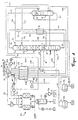
- air to be broken down is drawn in at 1 and in an air compressor 30 a first pressure, essentially medium pressure column pressure (plus line losses) compressed, pre-cooled in a cooling device 31 in direct contact with water and in a cleaning device (molecular sieve system) 32 in particular of water and Free of carbon dioxide.
- a first pressure essentially medium pressure column pressure (plus line losses) compressed, pre-cooled in a cooling device 31 in direct contact with water and in a cleaning device (molecular sieve system) 32 in particular of water and Free of carbon dioxide.
- the cleaned air is divided into three sub-streams, the first of which without further measures to increase pressure via line 103, through a main heat exchanger 2 and is introduced via line 104 into a medium pressure column 6.
- the medium pressure column 6 is - according to the respective product specification and the pressure loss - under operated at a pressure of 2 to 4 bar, preferably about 2.5 to 3.5 bar.
- the second partial flow of the cleaned air is in a post-compressor 202 essential pressure column pressure (plus line losses) compressed, in Main heat exchanger 2 in indirect heat exchange with cold process streams cooled to dew point temperature and introduced into the bottom of a pressure column 7 (see positions 201,202,203,2,204 and 7).
- the pressure column 7 is at one Working pressure of 5 to 10 bar, preferably operated 5.5 to 6.5 bar and is over a main capacitor 3 thermally coupled to a low pressure column 5.
- Latter works at a pressure of 1.1 to 2.0 bar, preferably 1.3 to 1.7 bar.
- the Air post-compressor 202 can be driven by the same motor shaft as that Air compressor 30.
- the third partial flow is fed via a line 301 to a compressor station 305 for Turbine air (306, 307, 308) into a turbine 309 and / or for rectification air (313, 314, 315), the intake pressure 303 using a throttle device 302 can be reduced especially in underload operation.
- the air of the third partial flow is about in the compression station 305
- Medium pressure column pressure compressed to a pressure equal to an air condensation temperature corresponds, which is at least approximately equal to Evaporation temperature of the liquid pressurized oxygen 17 is alternatively the third partial flow of the cleaned air also on the pressure side of the air post-compressor 202 are branched off when air (312) from the expansion turbine 309 is fed into the pressure column 7.
- the suction pressure of the compressor station 305 then corresponds to the pressure column pressure.
- a first portion 307 of the highly compressed air 306 is at a temperature 308 which between the temperatures at the warm and cold ends of the Main heat exchanger 2 is fed to the expansion turbine 309 and there for example, medium pressure column pressure relaxed while working.
- the embodiment is the turbine output by a brake generator to the The relaxed turbine outlet flow is partly through the Main heat exchanger 2 via lines 310,311 and 304 to the suction side of the Compressor station 305 returned, partly via line 312 in the bottom of the Medium pressure column 6 fed.
- a second part 313 of the highly compressed air 306 is against the evaporating Pressurized oxygen 17 at least partially, preferably completely or in essentially completely liquefied, to a part 314 above the sump in the Low pressure column 5 and another part 315 in the bottom of the pressure column 7 relaxed.
- Bottom liquid 70 and washing nitrogen 74 from the top of the pressure column 7 are in a supercooling counterflow 4 against a residual gas flow 50
- Low pressure column 5 supercooled and in each case in the low pressure column 5 and / or in the Medium pressure column relaxed (lines 71, 72, 73, 75, 76 and 77).
- Bottom liquid 60 and washing nitrogen 61 from the medium pressure column are also in the Subcooling countercurrent 4 subcooled against the residual gas stream 50 (not in Figure 1 shown) or the bottom liquid 60 directly into the top condenser 10 of the Medium pressure column and the washing nitrogen 61 on the head of the low pressure column 5 given up.
- a residual gas stream 51 and products from the rectification section, in Example GOX and DGOX are approximately in the main heat exchanger 2 Ambient temperature warmed up (lines 51, 52, 54, 55, 17 and 18).
- the Residual gas stream 52 can be completely or partially as stream 53 for the regeneration of the Molecular sieve station 32 can be used.
- Liquid oxygen 15 is taken from the bottom of the low pressure column, depending on Product specification with the help of an oxygen pump 16 to the required Delivery pressure compressed or completely or partially into a removable storage tank 80 filled.
- Liquid nitrogen 78 is drawn off from the top of the low pressure column 5 or branched off from one of the washing nitrogen lines 75 or 61 and likewise internally compressed (not shown in FIG. 1) or in a removable storage tank 79 fed.
- the compressor station 305 consists of at least two in parallel switched compressors. This makes it possible to also use the removable storage system to operate as a pure gas apparatus, i.e. without liquid production the to generate internally compressed oxygen (DGOX).
- DGOX internally compressed oxygen
- one of the two compressors of the compression station 305 is taken out of operation and the second compressor takes over the task of compressing the inside Evaporate pressurized oxygen 17.
- the compressor station 305 thus exists according to the invention from two compressors, each with a different function, from one for the generation of cold for liquid production and the other for Evaporation of the internally compressed oxygen is used.
- the removable storage tanks 79 and 80 are used in the example of a time-limited Overproduction of DGOX, the removal of LOX and LIN as sales products, as Emergency supply tanks, as removable storage of the LOX and LIN cold contents and as Cooling supply with the cooling circuit switched off.
- the compressor station shown in FIG. 1 can be single-stage or multi-stage machines with intercooling and / or aftercooling included.
- the work output of the Expansion turbine 309 in the present embodiment to a booster transfer.
- the air throttle flow 313 is cooled in the Main heat exchanger 2 and subsequent isenthalpic relaxation in the Double column 5,7 compressed to a pressure which is at least as large as that Final pressure of the compressor station 305 of the exemplary embodiment in FIG. 1.
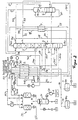
- air to be broken down is drawn in at 1 and in an air compressor 30 a first pressure, essentially medium pressure column pressure (plus line losses) compressed, pre-cooled in a cooling device 31 in direct contact with water and in a cleaning device (molecular sieve system) 32 in particular of water and Free of carbon dioxide.
- a first pressure essentially medium pressure column pressure (plus line losses) compressed, pre-cooled in a cooling device 31 in direct contact with water and in a cleaning device (molecular sieve system) 32 in particular of water and Free of carbon dioxide.
- the cleaned air is divided into three sub-streams, the first of which without further measures to increase pressure via line 103, through main heat exchanger 2 and can be introduced via line 104 into a medium pressure column 6.
- the Medium pressure column 6 is - according to the respective product specification and Pressure loss - under a pressure of 2 to 4 bar, preferably about 2.5 to 3.5 bar operated.
- the second partial flow of the cleaned air is applied to one in a post-compressor 202 Compresses pressure that corresponds to an air condensation temperature that at least approximately the same as the evaporation temperature of a liquid low-pressure oxygen 15 is, in the main heat exchanger 2 in indirect heat exchange with cold Process streams cooled and in a bottom condenser 3 of the low pressure column 5 introduced (see positions 201, 202, 203, 2, 204 and 3).
- the Air post-compressor 202 can be driven by the same motor shaft as that Air compressor 30.
- the two-column apparatus shown works with high oxygen purities (greater than 99.5%) in the limit case over into the normal double column apparatus (see e.g. patent DE 195 26 785 C1).
- the second partial flow then goes to zero and that Low pressure column taps of streams 62 and 63 shift towards the swamp the low pressure column 5, so that the top capacitor 10 to the main capacitor of the Double column is and the pressure of the medium pressure column corresponding to the thermal coupling increased
- the third partial flow is fed via a line 301 to a compressor station 305 for Turbine air (306, 307, 308) into a turbine 309 and / or for rectification air (313, 314, 315) supplied, the suction pressure 303 thereof with the aid of a throttle device 302 can be reduced in particular in underload operation.
- the air of the third Partial flow is in the compressor station 305 from about medium pressure column pressure compresses a pressure that corresponds to an air condensation temperature that at least approximately equal to the vaporization temperature of the liquid pressurized oxygen 17 is.
- a first partial stream 307 of the highly compressed air 306 is fed via line 308 to a Temperature that is between the temperatures at the warm and cold ends of the Main heat exchanger 2 is fed to the expansion turbine 309 and there for example, medium pressure column pressure relaxed while working.
- the embodiment is the turbine output by a brake generator to the The relaxed turbine outlet flow is partly through the Main heat exchanger 2 via lines 310,311 and 304 to the suction side of the Compressor station 305 returned, partly via line 312 in the bottom of the Medium pressure column 6 fed
- a second partial flow 313 of the highly compressed air 306 is against the evaporating pressurized oxygen 17 at least partially, preferably completely or essentially completely liquefied, to a part 314 above the sump in the low pressure column 5 and another part 315 in the swamp of the Medium pressure column 6 relaxed.
- Liquid oxygen 15 is taken from the bottom of the low pressure column, depending on Product specification with the help of an oxygen pump 16 to the required Delivery pressure compressed or completely or partially into a removable storage tank 80 filled.
- Liquid nitrogen 78 is drawn off from the top of the low pressure column 5 or branched off from the washing nitrogen line 61 and likewise internally compressed (in 1 not shown) or fed into the removable storage tank 79.
- the compressor station 305 consists of at least two in parallel switched compressors. This makes it possible to also use the removable storage system to operate as a pure gas apparatus, i.e. without liquid production the to generate internally compressed oxygen (DGOX).
- DGOX internally compressed oxygen
- one of the two compressors of the compression station 305 is taken out of operation and the second compressor takes over the task of compressing the inside Evaporate pressurized oxygen 17.
- the compressor station 305 thus exists according to the invention from two compressors, each with a different function, from one for the generation of cold for liquid production and the other for Evaporation of the internally compressed oxygen is used.
- the removable storage tanks 79 and 80 are used in the example of a time-limited Overproduction of DGOX, the removal of LOX and LIN as sales products, as Emergency supply tanks, as removable storage of the LOX and LIN cold contents and as Cooling supply with the cooling circuit switched off.
- the compressor station shown in FIG. 3 can be single-stage or multi-stage machines with intercooling and / or aftercooling included.
- the work performance of the Expansion turbine 309 in the present embodiment to a booster transfer.
- the air throttle flow 313 is cooled in the Main heat exchanger 2 and subsequent isenthalpic expansion into the columns 5 and 6 compressed to a pressure at least as large as the ultimate pressure of the Compressor station 305 of the exemplary embodiment in FIG. 3.
- the table shows the product flows, the alternating storage flows, for the (circulation and throttle air) compressor station the number of compressors in operation, the air flows and the energy requirements of the system. All gas and liquid flows are given in m 3 / h, whereby m 3 / h in the normal state are meant at 1atm and 273 K.
- the operating cases A1, A2 and A3 are characterized in that both compressors of the compressor station are in operation and supply a turbine flow and a throttle flow.
Landscapes
- Engineering & Computer Science (AREA)
- Physics & Mathematics (AREA)
- Mechanical Engineering (AREA)
- Thermal Sciences (AREA)
- General Engineering & Computer Science (AREA)
- Health & Medical Sciences (AREA)
- Emergency Medicine (AREA)
- Separation By Low-Temperature Treatments (AREA)
- Organic Low-Molecular-Weight Compounds And Preparation Thereof (AREA)
- Separation Of Gases By Adsorption (AREA)
Claims (12)
- Procédé en vue de la production d'un produit comprimé gazeux par fractionnement à basse température d'air, qui est exploité par moments dans un fonctionnement à gaz et par moments dans un fonctionnement combiné,
étant donné que, dans le fonctionnement à gaz et dans le fonctionnement combiné,étant donné que, dans le fonctionnement combiné, du produit comprimé gazeux et du produit liquide sont obtenus etde l'air de charge purifié est refroidi sous surpression, partiellement liquéfié et soumis, en vue de l'extraction de fractions gazeuses et liquides, à une rectification,du liquide réfrigéré d'au moins une des fractions liquides provenant de la rectification sous pression élevée est évaporé par échange thermique indirect avec l'air de charge, est échauffé et est obtenu en tant que produit comprimé gazeux,et étant donné que, au cours du fonctionnement à gaz, le débit d'air dans le cycle frigorifique est réduit à zéro et que du liquide stocké réfrigéré est utilisé pour compenser les pertes de froid, qui ne peuvent plus être couvertes par le cycle frigorifique.que le froid requis à cet effet est produit dans un cycle frigorifique d'air, dans lequel l'air est comprimé dans le cycle frigorifique et est détendu en fournissant du travail, de la chaleur étant retirée ce faisant de l'air, et l'air détendu en fournissant du travail étant à nouveau réchauffé, au moins en partie à contre-courant de l'air de charge à refroidir et étant alors à nouveau comprimé en retour,que le liquide réfrigéré est produit par rectification et est au moins stocké en partie, - Procédé selon la revendication 1, caractérisé en ce que le liquide réfrigéré d'au moins une fraction liquide provenant de la rectification, par exemple, l'azote liquide (LIN), l'oxygène liquide (LOX) ou l'air liquide, est stocké de manière intermédiaire dans un réservoir en vue de la compensation des pertes de froid dans le fonctionnement à gaz, des récipients tampon et/ou les réservoirs de produit étant utilisés en tant que réservoir en vue du stockage de ces fractions.
- Procédé selon la revendication 1, caractérisé en ce que l'on effectue par moments, par utilisation d'au moins deux réservoirs, un stockage alternant, étant donné que, d'une part, dans le cas d'une demande en oxygène comprimé accrue (DGOX), en plus du LOX provenant de la rectification, du LOX stocké de manière intermédiaire dans un réservoir est prélevé, comprimé, évaporé à contre-courant et échauffé et alors fourni en tant que produit DGOX et que, de ce fait, en contre courant, du froid est récupéré et est utilisé en vue de la production et du stockage intermédiaire de produit LIN, étant donné que, d'autre part, en cas de demande affaiblie de DGOX, suffisamment peu de LOX est extrait en tant que DGOX du système de rectification et qu'à titre de compensation, plus de LOX est stocké de manière intermédiaire.
- Procédé selon l'une quelconque des revendications 1 à 3, caractérisé en ce que l'on utilise un procédé à deux colonnes, un refroidissement de tête de la colonne sous pression étant réalisé à l'aide d'un liquide intermédiaire provenant d'une colonne basse pression et un chauffage du puits de la colonne basse pression étant effectué par échange thermique indirect avec l'air.
- Procédé selon l'une quelconque des revendications 1 à 3, caractérisé en ce que l'on utilise, en tant que système de rectification, un procédé à trois colonnes, une colonne double ayant une section haute pression et une section basse pression et une colonne auxiliaire sous une pression intermédiaire étant utilisées.
- Procédé selon l'une quelconque des revendications 1 à 5, caractérisé en ce qu'en tant qu'air de charge, qui est amené en échange thermique indirect avec le liquide réfrigéré qui s'évapore, à partir duquel l'on extrait le produit comprimé gazeux, l'on utilise l'air en provenance du cycle frigorifique en aval de la compression ou de l'air qui a subi une post-compression en aval de la compression.
- Procédé selon l'une quelconque des revendications 1 à 6, caractérisé en ce que la détente fournissant du travail se fait dans au moins une turbine à expansion, la puissance sur l'arbre d'une turbine de ce genre étant utilisée en vue de l'entraínement d'un générateur produisant du courant ou d'un booster, le booster étant utilisé par exemple, en vue de la post-compression de l'air dans le cycle frigorifique.
- Dispositif en vue de l'exécution du procédé selon l'une quelconque des revendications 1 à 7, ayantet le poste de compression étant exécuté avec au moins deux compresseurs disposés en parallèle, lesquels sont arrangés de telle sorte qu'en cas de fonctionnement à gaz un seul des compresseurs est en fonctionnement, ce compresseur livrant l'air d'étranglement et le cycle frigorifique n'étant pas alimenté en air, alors qu'en cas de fonctionnement combiné, avec la production de produit comprimé et de produit liquide, au moins deux compresseurs disposés en parallèle sont en fonctionnement et qu'en outre, pour fournir l'air d'étranglement, le cycle frigorifique est également alimenté en air et que le dispositif présente des moyens en vue du stockage de produit liquide.un compresseur principal pour l'air de charge, la pression de sortie du compresseur d'air principal étant aussi la pression de travail d'une unité de purification subséquente,un conduit d'air pur en provenance de l'unité de purification allant vers un poste de compression pour l'air dans le cycle frigorifique et pour l'air pour la rectification,et un conduit sous pression en provenance du poste de compression, qui débouche, d'une part, dans une tubulure de conduits du cycle frigorifique avec au moins une turbine à expansion et, d'autre part, dans une dérivation pour l'air d'étranglement vers les colonnes,
- Dispositif selon la revendication 8, caractérisé en ce que la turbine à expansion est construite dans le passage de conduits du cycle frigorifique en tant qu'unité turbines/générateur.
- Dispositif selon la revendication 8, caractérisé en ce que la turbine à expansion est construite dans le passage de conduits du cycle frigorifique en tant qu'unité turbines/booster, le booster étant branché dans la tubulure de conduits du cycle frigorifique en tant que post-compresseur d'air en provenance du poste de compression.
- Dispositif selon la revendication 8 ou 9, caractérisé en ce que l'on dispose dans la tubulure de conduits pour l'air d'étranglement un post-compresseur pour l'air provenant du poste de compression.
- Utilisation du procédé selon l'une quelconque des revendications 1 à 7, et du dispositif selon l'une quelconque des revendications 8 à 11, dans une installation de fractionnement de l'air en vue de la fourniture d'une usine sidérurgique en azote et en oxygène.
Priority Applications (1)
| Application Number | Priority Date | Filing Date | Title |
|---|---|---|---|
| EP19990106715 EP0949471B1 (fr) | 1998-04-08 | 1999-04-01 | Unité de séparation de l'air à deux modes de fonctionnement |
Applications Claiming Priority (5)
| Application Number | Priority Date | Filing Date | Title |
|---|---|---|---|
| DE19815885 | 1998-04-08 | ||
| DE1998115885 DE19815885A1 (de) | 1998-04-08 | 1998-04-08 | Verfahren und Vorrichtung zur Erzeugung von gasförmigem Druckprodukt bei der Tieftemperaturzerlegung von Luft |
| EP98112276 | 1998-07-02 | ||
| EP98112276 | 1998-07-02 | ||
| EP19990106715 EP0949471B1 (fr) | 1998-04-08 | 1999-04-01 | Unité de séparation de l'air à deux modes de fonctionnement |
Publications (2)
| Publication Number | Publication Date |
|---|---|
| EP0949471A1 EP0949471A1 (fr) | 1999-10-13 |
| EP0949471B1 true EP0949471B1 (fr) | 2002-12-18 |
Family
ID=7864076
Family Applications (1)
| Application Number | Title | Priority Date | Filing Date |
|---|---|---|---|
| EP19990106715 Expired - Lifetime EP0949471B1 (fr) | 1998-04-08 | 1999-04-01 | Unité de séparation de l'air à deux modes de fonctionnement |
Country Status (7)
| Country | Link |
|---|---|
| US (1) | US6185960B1 (fr) |
| EP (1) | EP0949471B1 (fr) |
| AT (1) | ATE230098T1 (fr) |
| CZ (1) | CZ297724B6 (fr) |
| DE (1) | DE19815885A1 (fr) |
| HU (1) | HUP9900988A2 (fr) |
| PL (1) | PL191500B1 (fr) |
Cited By (19)
| Publication number | Priority date | Publication date | Assignee | Title |
|---|---|---|---|---|
| DE102007031759A1 (de) | 2007-07-07 | 2009-01-08 | Linde Ag | Verfahren und Vorrichtung zur Erzeugung von gasförmigem Druckprodukt durch Tieftemperaturzerlegung von Luft |
| DE102007031765A1 (de) | 2007-07-07 | 2009-01-08 | Linde Ag | Verfahren zur Tieftemperaturzerlegung von Luft |
| DE102009034979A1 (de) | 2009-04-28 | 2010-11-04 | Linde Aktiengesellschaft | Verfahren und Vorrichtung zur Erzeugung von gasförmigem Drucksauerstoff |
| EP2312248A1 (fr) | 2009-10-07 | 2011-04-20 | Linde Aktiengesellschaft | Procédé et dispositif de production d'oxygène sous pression et de crypton/xénon |
| EP2458311A1 (fr) | 2010-11-25 | 2012-05-30 | Linde Aktiengesellschaft | Procédé et dispositif de production d'un produit d'impression gazeux par décomposition à basse température d'air |
| DE102010052544A1 (de) | 2010-11-25 | 2012-05-31 | Linde Ag | Verfahren zur Gewinnung eines gasförmigen Druckprodukts durch Tieftemperaturzerlegung von Luft |
| EP2520886A1 (fr) | 2011-05-05 | 2012-11-07 | Linde AG | Procédé et dispositif de production d'un produit comprimé à oxygène gazeux par décomposition à basse température d'air |
| EP2568242A1 (fr) | 2011-09-08 | 2013-03-13 | Linde Aktiengesellschaft | Procédé et dispositif destinés à la production d'acier |
| EP2600090A1 (fr) | 2011-12-01 | 2013-06-05 | Linde Aktiengesellschaft | Procédé et dispositif destinés à la production d'oxygène sous pression par décomposition à basse température de l'air |
| DE102011121314A1 (de) | 2011-12-16 | 2013-06-20 | Linde Aktiengesellschaft | Verfahren zur Erzeugung eines gasförmigen Sauerstoff-Druckprodukts durch Tieftemperaturzerlegung von Luft |
| DE102013017590A1 (de) | 2013-10-22 | 2014-01-02 | Linde Aktiengesellschaft | Verfahren zur Gewinnung eines Krypton und Xenon enthaltenden Fluids und hierfür eingerichtete Luftzerlegungsanlage |
| DE102012017488A1 (de) | 2012-09-04 | 2014-03-06 | Linde Aktiengesellschaft | Verfahren zur Erstellung einer Luftzerlegungsanlage, Luftzerlegungsanlage und zugehöriges Betriebsverfahren |
| EP2784420A1 (fr) | 2013-03-26 | 2014-10-01 | Linde Aktiengesellschaft | Procédé de séparation de l'air et installation de séparation de l'air |
| WO2014154339A2 (fr) | 2013-03-26 | 2014-10-02 | Linde Aktiengesellschaft | Procédé de séparation d'air et installation de séparation d'air |
| EP2801777A1 (fr) | 2013-05-08 | 2014-11-12 | Linde Aktiengesellschaft | Installation de décomposition de l'air dotée d'un entraînement de compresseur principal |
| EP2963367A1 (fr) | 2014-07-05 | 2016-01-06 | Linde Aktiengesellschaft | Procédé et dispositif cryogéniques de séparation d'air avec consommation d'énergie variable |
| EP2963371A1 (fr) | 2014-07-05 | 2016-01-06 | Linde Aktiengesellschaft | Procede et dispositif de production d'un produit de gaz sous pression par decomposition a basse temperature d'air |
| EP2963370A1 (fr) | 2014-07-05 | 2016-01-06 | Linde Aktiengesellschaft | Procede et dispositif cryogeniques de separation d'air |
| EP2963369A1 (fr) | 2014-07-05 | 2016-01-06 | Linde Aktiengesellschaft | Procede et dispositif cryogeniques de separation d'air |
Families Citing this family (32)
| Publication number | Priority date | Publication date | Assignee | Title |
|---|---|---|---|---|
| GB0002084D0 (en) * | 2000-01-28 | 2000-03-22 | Boc Group Plc | Air separation method |
| DE10015602A1 (de) * | 2000-03-29 | 2001-10-04 | Linde Ag | Verfahren und Vorrichtung zur Gewinnung eines Druckprodukts durch Tieftemperaturzerlegung von Luft |
| US6438990B1 (en) * | 2000-06-12 | 2002-08-27 | Jay K. Hertling | Refrigeration system |
| EP1207362A1 (fr) | 2000-10-23 | 2002-05-22 | Air Products And Chemicals, Inc. | Procédé et appareil pour la production d'oxygène gazeux à basse pression |
| DE10103968A1 (de) * | 2001-01-30 | 2002-08-01 | Linde Ag | Drei-Säulen-System zur Tieftemperaturzerlegung von Luft |
| DE10111428A1 (de) | 2001-03-09 | 2002-09-12 | Linde Ag | Verfahren und Vorrichtung zur Zerlegung eines Gasgemischs mit Notbetrieb |
| FR2831249A1 (fr) * | 2002-01-21 | 2003-04-25 | Air Liquide | Procede et installation de separation d'air par distillation cryogenique |
| FR2844344B1 (fr) * | 2002-09-11 | 2005-04-08 | Air Liquide | Installation de production de grandes quantites d'oxygene et/ou d'azote |
| DE10249383A1 (de) * | 2002-10-23 | 2004-05-06 | Linde Ag | Verfahren und Vorrichtung zur variablen Erzeugung von Sauerstoff durch Tieftemperatur-Zerlegung von Luft |
| FR2854682B1 (fr) * | 2003-05-05 | 2005-06-17 | Air Liquide | Procede et installation de separation d'air par distillation cryogenique |
| EP1582830A1 (fr) * | 2004-03-29 | 2005-10-05 | Air Products And Chemicals, Inc. | Procédé et dispositif pour la séparation cryogénique de l'air |
| DE102004016931A1 (de) * | 2004-04-06 | 2005-10-27 | Linde Ag | Verfahren und Vorrichtung zur variablen Erzeugung eines Druckproduktes durch Tieftemperaturzerlegung von Luft |
| US7272954B2 (en) * | 2004-07-14 | 2007-09-25 | L'air Liquide, Societe Anonyme A Directoire Et Conseil De Surveillance Pour L'etude Et L'exploitation Des Proceded Georges Claude | Low temperature air separation process for producing pressurized gaseous product |
| US7263859B2 (en) * | 2004-12-27 | 2007-09-04 | L'air Liquide, Societe Anonyme A Directoire Et Conseil De Surveillance Pour L'etude Et L'exploitation Des Procedes Georges Claude | Process and apparatus for cooling a stream of compressed air |
| JP5005894B2 (ja) * | 2005-06-23 | 2012-08-22 | エア・ウォーター株式会社 | 窒素発生方法およびそれに用いる装置 |
| US20070251267A1 (en) * | 2006-04-26 | 2007-11-01 | Bao Ha | Cryogenic Air Separation Process |
| EP1921399A3 (fr) * | 2006-11-13 | 2010-03-10 | Hussmann Corporation | Système de réfrigération transcritique à deux étapes |
| US20080115531A1 (en) * | 2006-11-16 | 2008-05-22 | Bao Ha | Cryogenic Air Separation Process and Apparatus |
| DE102007051184A1 (de) * | 2007-10-25 | 2009-04-30 | Linde Aktiengesellschaft | Verfahren und Vorrichtung zur Tieftemperatur-Luftzerlegung |
| DE102007051183A1 (de) * | 2007-10-25 | 2009-04-30 | Linde Aktiengesellschaft | Verfahren zur Tieftemperatur-Luftzerlegung |
| DE102009023900A1 (de) | 2009-06-04 | 2010-12-09 | Linde Aktiengesellschaft | Dreisäulenverfahren und -vorrichtung zur Tieftemperaturzerlegung von Luft |
| CN102032755A (zh) * | 2010-08-03 | 2011-04-27 | 苏州制氧机有限责任公司 | 空气分离装置 |
| CN102072612B (zh) * | 2010-10-19 | 2013-05-29 | 上海加力气体有限公司 | N型模式节能制气方法 |
| US20160003536A1 (en) * | 2013-03-28 | 2016-01-07 | Linde Aktiengesellschaft | Method and device for producing gaseous compressed oxygen having variable power consumption |
| EP2824407A1 (fr) * | 2013-07-11 | 2015-01-14 | Linde Aktiengesellschaft | Procédé de génération d'au moins un produit de l'air, installation de décomposition de l'air, procédé et dispositif de production d'énergie électrique |
| EP3193114B1 (fr) * | 2016-01-14 | 2019-08-21 | Linde Aktiengesellschaft | Procédé de production d'un produit d'air dans une installation de séparation d'air et installation de séparation d'air |
| HUE045459T2 (hu) * | 2017-06-02 | 2019-12-30 | Linde Ag | Eljárás egy vagy több levegõtermék kinyerésére és levegõszétválasztó létesítmény |
| CN112654827B (zh) | 2018-10-09 | 2022-12-06 | 林德有限责任公司 | 用于提取一种或多种空气产物的方法和空气分离设备 |
| US10914517B2 (en) * | 2018-11-16 | 2021-02-09 | L'air Liquide Societe Anonyme Pour L'etude Et L'exploitation Des Procedes Georges Claude | Method for utilizing waste air to improve the capacity of an existing air separation unit |
| FR3099819B1 (fr) * | 2019-08-05 | 2021-09-10 | Air Liquide | Dispositif et installation de réfrigération |
| CN110608583B (zh) * | 2019-09-12 | 2021-07-23 | 北京首钢股份有限公司 | 一种压力控制方法及装置 |
| CN113686099B (zh) * | 2021-08-09 | 2022-08-09 | 北京科技大学 | 一种基于内压缩空分储能装置的物质回收方法 |
Family Cites Families (8)
| Publication number | Priority date | Publication date | Assignee | Title |
|---|---|---|---|---|
| CS184647B1 (en) * | 1976-09-29 | 1978-08-31 | Jiri Sykora | Method of and apparatus for manufacturing liquid air separation products and pressurized oxygen |
| GB2080929B (en) * | 1980-07-22 | 1984-02-08 | Air Prod & Chem | Producing gaseous oxygen |
| DE3913880A1 (de) * | 1989-04-27 | 1990-10-31 | Linde Ag | Verfahren und vorrichtung zur tieftemperaturzerlegung von luft |
| FR2701553B1 (fr) * | 1993-02-12 | 1995-04-28 | Maurice Grenier | Procédé et installation de production d'oxygène sous pression. |
| FR2704632B1 (fr) * | 1993-04-29 | 1995-06-23 | Air Liquide | Procede et installation pour la separation de l'air. |
| FR2706195B1 (fr) * | 1993-06-07 | 1995-07-28 | Air Liquide | Procédé et unité de fourniture d'un gaz sous pression à une installation consommatrice d'un constituant de l'air. |
| US5666823A (en) * | 1996-01-31 | 1997-09-16 | Air Products And Chemicals, Inc. | High pressure combustion turbine and air separation system integration |
| US5678425A (en) * | 1996-06-07 | 1997-10-21 | Air Products And Chemicals, Inc. | Method and apparatus for producing liquid products from air in various proportions |
-
1998
- 1998-04-08 DE DE1998115885 patent/DE19815885A1/de not_active Withdrawn
-
1999
- 1999-04-01 EP EP19990106715 patent/EP0949471B1/fr not_active Expired - Lifetime
- 1999-04-01 AT AT99106715T patent/ATE230098T1/de active
- 1999-04-07 PL PL332409A patent/PL191500B1/pl unknown
- 1999-04-07 CZ CZ0121399A patent/CZ297724B6/cs not_active IP Right Cessation
- 1999-04-08 US US09/288,226 patent/US6185960B1/en not_active Expired - Fee Related
- 1999-04-08 HU HU9900988A patent/HUP9900988A2/hu unknown
Cited By (25)
| Publication number | Priority date | Publication date | Assignee | Title |
|---|---|---|---|---|
| DE102007031759A1 (de) | 2007-07-07 | 2009-01-08 | Linde Ag | Verfahren und Vorrichtung zur Erzeugung von gasförmigem Druckprodukt durch Tieftemperaturzerlegung von Luft |
| DE102007031765A1 (de) | 2007-07-07 | 2009-01-08 | Linde Ag | Verfahren zur Tieftemperaturzerlegung von Luft |
| EP2015012A2 (fr) | 2007-07-07 | 2009-01-14 | Linde Aktiengesellschaft | Procédé pour la séparation cryogénique d'air |
| EP2015013A2 (fr) | 2007-07-07 | 2009-01-14 | Linde Aktiengesellschaft | Procédé et dispositif de production d'un gaz sous pression par séparation cryogénique d'air |
| DE102009034979A1 (de) | 2009-04-28 | 2010-11-04 | Linde Aktiengesellschaft | Verfahren und Vorrichtung zur Erzeugung von gasförmigem Drucksauerstoff |
| EP2312248A1 (fr) | 2009-10-07 | 2011-04-20 | Linde Aktiengesellschaft | Procédé et dispositif de production d'oxygène sous pression et de crypton/xénon |
| EP2458311A1 (fr) | 2010-11-25 | 2012-05-30 | Linde Aktiengesellschaft | Procédé et dispositif de production d'un produit d'impression gazeux par décomposition à basse température d'air |
| DE102010052544A1 (de) | 2010-11-25 | 2012-05-31 | Linde Ag | Verfahren zur Gewinnung eines gasförmigen Druckprodukts durch Tieftemperaturzerlegung von Luft |
| DE102010052545A1 (de) | 2010-11-25 | 2012-05-31 | Linde Aktiengesellschaft | Verfahren und Vorrichtung zur Gewinnung eines gasförmigen Druckprodukts durch Tieftemperaturzerlegung von Luft |
| EP2466236A1 (fr) | 2010-11-25 | 2012-06-20 | Linde Aktiengesellschaft | Procédé de production d'un produit d'impression gazeux par décomposition à basse température de l'air |
| EP2520886A1 (fr) | 2011-05-05 | 2012-11-07 | Linde AG | Procédé et dispositif de production d'un produit comprimé à oxygène gazeux par décomposition à basse température d'air |
| DE102011112909A1 (de) | 2011-09-08 | 2013-03-14 | Linde Aktiengesellschaft | Verfahren und Vorrichtung zur Gewinnung von Stahl |
| EP2568242A1 (fr) | 2011-09-08 | 2013-03-13 | Linde Aktiengesellschaft | Procédé et dispositif destinés à la production d'acier |
| EP2600090A1 (fr) | 2011-12-01 | 2013-06-05 | Linde Aktiengesellschaft | Procédé et dispositif destinés à la production d'oxygène sous pression par décomposition à basse température de l'air |
| DE102011121314A1 (de) | 2011-12-16 | 2013-06-20 | Linde Aktiengesellschaft | Verfahren zur Erzeugung eines gasförmigen Sauerstoff-Druckprodukts durch Tieftemperaturzerlegung von Luft |
| DE102012017488A1 (de) | 2012-09-04 | 2014-03-06 | Linde Aktiengesellschaft | Verfahren zur Erstellung einer Luftzerlegungsanlage, Luftzerlegungsanlage und zugehöriges Betriebsverfahren |
| EP2784420A1 (fr) | 2013-03-26 | 2014-10-01 | Linde Aktiengesellschaft | Procédé de séparation de l'air et installation de séparation de l'air |
| WO2014154339A2 (fr) | 2013-03-26 | 2014-10-02 | Linde Aktiengesellschaft | Procédé de séparation d'air et installation de séparation d'air |
| EP2801777A1 (fr) | 2013-05-08 | 2014-11-12 | Linde Aktiengesellschaft | Installation de décomposition de l'air dotée d'un entraînement de compresseur principal |
| DE102013017590A1 (de) | 2013-10-22 | 2014-01-02 | Linde Aktiengesellschaft | Verfahren zur Gewinnung eines Krypton und Xenon enthaltenden Fluids und hierfür eingerichtete Luftzerlegungsanlage |
| EP2963367A1 (fr) | 2014-07-05 | 2016-01-06 | Linde Aktiengesellschaft | Procédé et dispositif cryogéniques de séparation d'air avec consommation d'énergie variable |
| EP2963371A1 (fr) | 2014-07-05 | 2016-01-06 | Linde Aktiengesellschaft | Procede et dispositif de production d'un produit de gaz sous pression par decomposition a basse temperature d'air |
| EP2963370A1 (fr) | 2014-07-05 | 2016-01-06 | Linde Aktiengesellschaft | Procede et dispositif cryogeniques de separation d'air |
| EP2963369A1 (fr) | 2014-07-05 | 2016-01-06 | Linde Aktiengesellschaft | Procede et dispositif cryogeniques de separation d'air |
| WO2016005031A1 (fr) | 2014-07-05 | 2016-01-14 | Linde Aktiengesellschaft | Procédé et dispositif de fractionnement de l'air à basse température à consommation d'énergie variable |
Also Published As
| Publication number | Publication date |
|---|---|
| CZ297724B6 (cs) | 2007-03-14 |
| DE19815885A1 (de) | 1999-10-14 |
| HU9900988D0 (en) | 1999-06-28 |
| CZ9901213A3 (cs) | 2001-02-14 |
| EP0949471A1 (fr) | 1999-10-13 |
| HUP9900988A2 (hu) | 2003-06-28 |
| ATE230098T1 (de) | 2003-01-15 |
| US6185960B1 (en) | 2001-02-13 |
| PL332409A1 (en) | 1999-10-11 |
| PL191500B1 (pl) | 2006-05-31 |
Similar Documents
| Publication | Publication Date | Title |
|---|---|---|
| EP0949471B1 (fr) | Unité de séparation de l'air à deux modes de fonctionnement | |
| DE69413918T2 (de) | Tieftemperaturzerlegung von Luft | |
| EP0842385B1 (fr) | Procede et dispositif de production variable d'un produit gazeux comprime | |
| EP0093448B1 (fr) | Procédé et dispositif pour obtenir de l'oxygène gazeux sous pression élevée | |
| EP1067345B1 (fr) | Procédé et dispositif pour la séparation cryogénique des constituants de l'air | |
| DE69205424T2 (de) | Verfahren und Vorrichtung für die Luftzerlegung durch Rektifikation. | |
| DE19529681C2 (de) | Verfahren und Vorrichtung zur Luftzerlegung durch Tieftemperaturrektifikation | |
| DE69509841T2 (de) | Verfahren und Vorrichtung zur Herstellung von Sauerstoff | |
| EP1134525B1 (fr) | Procédé de production d'azote liquide et gazeux avec une quantité variable de liquide | |
| DE69201522T2 (de) | Hochdruck-Lufttrennungsverfahren mit Gewinnung von Flüssigkeit. | |
| DE19803437A1 (de) | Verfahren und Vorrichtung zur Gewinnung eines Druckprodukts durch Tieftemperaturzerlegung von Luft | |
| EP1284404A1 (fr) | Procédé et dispositif pour la production d'un produit sous pression par séparation cryogénique de l'air | |
| EP3019803B1 (fr) | Procédé et dispositif permettant d'obtenir de l'oxygène par fractionnement cryogénique d'air avec une consommation variable d'énergie | |
| DE69209835T2 (de) | Einsäulenluftzerlegungszyklus und dessen Integration in Gasturbinen | |
| EP4018143A1 (fr) | Procédé de fonctionnement d'un échangeur de chaleur, agencement doté d'un échangeur de chaleur et système doté d'un agencement correspondant | |
| EP1146301A1 (fr) | Procédé et dispositif de production d'azote à haute pression par séparation d'air | |
| WO2020164799A1 (fr) | Procédé et installation pour fournir un ou plusieurs produits présents dans l'air, gazeux et à teneur élevée en oxygène | |
| EP0768503B1 (fr) | Procédé de séparation d'air à triple colonne | |
| WO2020200521A1 (fr) | Procédé pour faire fonctionner un échangeur de chaleur, ensemble pourvu d'un échangeur de chaleur et installation pourvue d'un ensemble correspondant | |
| EP3671085A1 (fr) | Dispositif et procédé de récupération de la chaleur de compression à partir de l'air comprimé et traité dans une installation de traitement de l'air | |
| DE69410040T2 (de) | Verfahren und Einrichtung zur Herstellung von wenigstens einem durch Zerlegung von Luft gewonnenem Gas unter Druck | |
| EP2647934A1 (fr) | Procédé et dispositif de génération d'énergie électrique | |
| DE10045128A1 (de) | Verfahren und Vorrichtung zur Erzeugung hoch reinen Stickstoffs durch Tieftemperatur-Luftzerlegung | |
| EP1209431B1 (fr) | Procédé et dispositif de production d'oxygène et d'azote | |
| EP1001236A2 (fr) | Procédé de production d'azote à ultra haute pureté |
Legal Events
| Date | Code | Title | Description |
|---|---|---|---|
| PUAI | Public reference made under article 153(3) epc to a published international application that has entered the european phase |
Free format text: ORIGINAL CODE: 0009012 |
|
| AK | Designated contracting states |
Kind code of ref document: A1 Designated state(s): AT BE CH DE DK ES FI FR GB IT LI NL SE |
|
| AX | Request for extension of the european patent |
Free format text: AL;LT;LV;MK;RO;SI |
|
| 17P | Request for examination filed |
Effective date: 19991005 |
|
| RAP1 | Party data changed (applicant data changed or rights of an application transferred) |
Owner name: LINDE TECHNISCHE GASE GMBH |
|
| AKX | Designation fees paid |
Free format text: AT BE CH DE DK ES FI FR GB IT LI NL SE |
|
| RAP1 | Party data changed (applicant data changed or rights of an application transferred) |
Owner name: LINDE GAS AG |
|
| 17Q | First examination report despatched |
Effective date: 20010919 |
|
| RAP1 | Party data changed (applicant data changed or rights of an application transferred) |
Owner name: LINDE AG |
|
| GRAG | Despatch of communication of intention to grant |
Free format text: ORIGINAL CODE: EPIDOS AGRA |
|
| GRAG | Despatch of communication of intention to grant |
Free format text: ORIGINAL CODE: EPIDOS AGRA |
|
| GRAH | Despatch of communication of intention to grant a patent |
Free format text: ORIGINAL CODE: EPIDOS IGRA |
|
| GRAH | Despatch of communication of intention to grant a patent |
Free format text: ORIGINAL CODE: EPIDOS IGRA |
|
| GRAA | (expected) grant |
Free format text: ORIGINAL CODE: 0009210 |
|
| AK | Designated contracting states |
Kind code of ref document: B1 Designated state(s): AT BE CH DE DK ES FI FR GB IT LI NL SE |
|
| PG25 | Lapsed in a contracting state [announced via postgrant information from national office to epo] |
Ref country code: FI Free format text: LAPSE BECAUSE OF FAILURE TO SUBMIT A TRANSLATION OF THE DESCRIPTION OR TO PAY THE FEE WITHIN THE PRESCRIBED TIME-LIMIT Effective date: 20021218 |
|
| REF | Corresponds to: |
Ref document number: 230098 Country of ref document: AT Date of ref document: 20030115 Kind code of ref document: T |
|
| REG | Reference to a national code |
Ref country code: GB Ref legal event code: FG4D Free format text: NOT ENGLISH |
|
| REG | Reference to a national code |
Ref country code: CH Ref legal event code: EP |
|
| REF | Corresponds to: |
Ref document number: 59903802 Country of ref document: DE Date of ref document: 20030130 Kind code of ref document: P Ref document number: 59903802 Country of ref document: DE Date of ref document: 20030130 |
|
| PG25 | Lapsed in a contracting state [announced via postgrant information from national office to epo] |
Ref country code: SE Free format text: LAPSE BECAUSE OF FAILURE TO SUBMIT A TRANSLATION OF THE DESCRIPTION OR TO PAY THE FEE WITHIN THE PRESCRIBED TIME-LIMIT Effective date: 20030318 Ref country code: DK Free format text: LAPSE BECAUSE OF FAILURE TO SUBMIT A TRANSLATION OF THE DESCRIPTION OR TO PAY THE FEE WITHIN THE PRESCRIBED TIME-LIMIT Effective date: 20030318 |
|
| GBT | Gb: translation of ep patent filed (gb section 77(6)(a)/1977) |
Effective date: 20030326 |
|
| PG25 | Lapsed in a contracting state [announced via postgrant information from national office to epo] |
Ref country code: LI Free format text: LAPSE BECAUSE OF NON-PAYMENT OF DUE FEES Effective date: 20030430 Ref country code: CH Free format text: LAPSE BECAUSE OF NON-PAYMENT OF DUE FEES Effective date: 20030430 Ref country code: BE Free format text: LAPSE BECAUSE OF NON-PAYMENT OF DUE FEES Effective date: 20030430 |
|
| PG25 | Lapsed in a contracting state [announced via postgrant information from national office to epo] |
Ref country code: ES Free format text: LAPSE BECAUSE OF FAILURE TO SUBMIT A TRANSLATION OF THE DESCRIPTION OR TO PAY THE FEE WITHIN THE PRESCRIBED TIME-LIMIT Effective date: 20030627 |
|
| ET | Fr: translation filed | ||
| PLBQ | Unpublished change to opponent data |
Free format text: ORIGINAL CODE: EPIDOS OPPO |
|
| PLBI | Opposition filed |
Free format text: ORIGINAL CODE: 0009260 |
|
| PLAZ | Examination of admissibility of opposition: despatch of communication + time limit |
Free format text: ORIGINAL CODE: EPIDOSNOPE2 |
|
| BERE | Be: lapsed |
Owner name: *LINDE A.G. Effective date: 20030430 |
|
| 26 | Opposition filed |
Opponent name: L'AIR LIQUIDE, S.A. A DIRECTOIRE ET CONSEIL DE SUR Effective date: 20030919 |
|
| REG | Reference to a national code |
Ref country code: CH Ref legal event code: PL |
|
| PLBG | Opposition deemed not to have been filed |
Free format text: ORIGINAL CODE: 0009274 |
|
| NLR1 | Nl: opposition has been filed with the epo |
Opponent name: L'AIR LIQUIDE, S.A. A DIRECTOIRE ET CONSEIL DE SUR |
|
| 26D | Opposition deemed not to have been filed |
Opponent name: L'AIR LIQUIDE, S.A. A DIRECTOIRE ET CONSEIL DE SUR Effective date: 20040115 |
|
| NLXE | Nl: other communications concerning ep-patents (part 3 heading xe) |
Free format text: PAT. BUL. 02/2004: THE OPPOSITION SHOULD BE DEEMED NOT TO HAVE BEEN FILED (SEE EUROPEAN PATENT BULLETIN 20040303/10) |
|
| PLAQ | Examination of admissibility of opposition: information related to despatch of communication + time limit deleted |
Free format text: ORIGINAL CODE: EPIDOSDOPE2 |
|
| PLBQ | Unpublished change to opponent data |
Free format text: ORIGINAL CODE: EPIDOS OPPO |
|
| PLAB | Opposition data, opponent's data or that of the opponent's representative modified |
Free format text: ORIGINAL CODE: 0009299OPPO |
|
| PLBE | No opposition filed within time limit |
Free format text: ORIGINAL CODE: 0009261 |
|
| STAA | Information on the status of an ep patent application or granted ep patent |
Free format text: STATUS: NO OPPOSITION FILED WITHIN TIME LIMIT |
|
| 26N | No opposition filed |
Effective date: 20040918 |
|
| REG | Reference to a national code |
Ref country code: FR Ref legal event code: CA |
|
| REG | Reference to a national code |
Ref country code: FR Ref legal event code: PLFP Year of fee payment: 18 |
|
| REG | Reference to a national code |
Ref country code: FR Ref legal event code: PLFP Year of fee payment: 19 |
|
| PGFP | Annual fee paid to national office [announced via postgrant information from national office to epo] |
Ref country code: FR Payment date: 20170313 Year of fee payment: 19 |
|
| PGFP | Annual fee paid to national office [announced via postgrant information from national office to epo] |
Ref country code: GB Payment date: 20170329 Year of fee payment: 19 |
|
| PGFP | Annual fee paid to national office [announced via postgrant information from national office to epo] |
Ref country code: NL Payment date: 20170412 Year of fee payment: 19 |
|
| PGFP | Annual fee paid to national office [announced via postgrant information from national office to epo] |
Ref country code: DE Payment date: 20170329 Year of fee payment: 19 |
|
| PGFP | Annual fee paid to national office [announced via postgrant information from national office to epo] |
Ref country code: IT Payment date: 20170420 Year of fee payment: 19 Ref country code: AT Payment date: 20170327 Year of fee payment: 19 |
|
| REG | Reference to a national code |
Ref country code: DE Ref legal event code: R119 Ref document number: 59903802 Country of ref document: DE |
|
| REG | Reference to a national code |
Ref country code: NL Ref legal event code: MM Effective date: 20180501 |
|
| REG | Reference to a national code |
Ref country code: AT Ref legal event code: MM01 Ref document number: 230098 Country of ref document: AT Kind code of ref document: T Effective date: 20180401 |
|
| GBPC | Gb: european patent ceased through non-payment of renewal fee |
Effective date: 20180401 |
|
| PG25 | Lapsed in a contracting state [announced via postgrant information from national office to epo] |
Ref country code: DE Free format text: LAPSE BECAUSE OF NON-PAYMENT OF DUE FEES Effective date: 20181101 Ref country code: AT Free format text: LAPSE BECAUSE OF NON-PAYMENT OF DUE FEES Effective date: 20180401 Ref country code: NL Free format text: LAPSE BECAUSE OF NON-PAYMENT OF DUE FEES Effective date: 20180501 |
|
| PG25 | Lapsed in a contracting state [announced via postgrant information from national office to epo] |
Ref country code: GB Free format text: LAPSE BECAUSE OF NON-PAYMENT OF DUE FEES Effective date: 20180401 |
|
| PG25 | Lapsed in a contracting state [announced via postgrant information from national office to epo] |
Ref country code: FR Free format text: LAPSE BECAUSE OF NON-PAYMENT OF DUE FEES Effective date: 20180430 Ref country code: IT Free format text: LAPSE BECAUSE OF NON-PAYMENT OF DUE FEES Effective date: 20180401 |