EP0949670A2 - Procédé et appareillage pour le montage "flip-chip" de composants électroniques - Google Patents
Procédé et appareillage pour le montage "flip-chip" de composants électroniques Download PDFInfo
- Publication number
- EP0949670A2 EP0949670A2 EP99106876A EP99106876A EP0949670A2 EP 0949670 A2 EP0949670 A2 EP 0949670A2 EP 99106876 A EP99106876 A EP 99106876A EP 99106876 A EP99106876 A EP 99106876A EP 0949670 A2 EP0949670 A2 EP 0949670A2
- Authority
- EP
- European Patent Office
- Prior art keywords
- electronic part
- ultrasonic vibration
- control unit
- defective
- bumps
- Prior art date
- Legal status (The legal status is an assumption and is not a legal conclusion. Google has not performed a legal analysis and makes no representation as to the accuracy of the status listed.)
- Granted
Links
Images


Classifications
-
- B—PERFORMING OPERATIONS; TRANSPORTING
- B23—MACHINE TOOLS; METAL-WORKING NOT OTHERWISE PROVIDED FOR
- B23K—SOLDERING OR UNSOLDERING; WELDING; CLADDING OR PLATING BY SOLDERING OR WELDING; CUTTING BY APPLYING HEAT LOCALLY, e.g. FLAME CUTTING; WORKING BY LASER BEAM
- B23K20/00—Non-electric welding by applying impact or other pressure, with or without the application of heat, e.g. cladding or plating
- B23K20/02—Non-electric welding by applying impact or other pressure, with or without the application of heat, e.g. cladding or plating by means of a press ; Diffusion bonding
- B23K20/023—Thermo-compression bonding
- B23K20/025—Bonding tips therefor
-
- B—PERFORMING OPERATIONS; TRANSPORTING
- B23—MACHINE TOOLS; METAL-WORKING NOT OTHERWISE PROVIDED FOR
- B23K—SOLDERING OR UNSOLDERING; WELDING; CLADDING OR PLATING BY SOLDERING OR WELDING; CUTTING BY APPLYING HEAT LOCALLY, e.g. FLAME CUTTING; WORKING BY LASER BEAM
- B23K20/00—Non-electric welding by applying impact or other pressure, with or without the application of heat, e.g. cladding or plating
- B23K20/10—Non-electric welding by applying impact or other pressure, with or without the application of heat, e.g. cladding or plating making use of vibrations, e.g. ultrasonic welding
- B23K20/106—Features related to sonotrodes
-
- B—PERFORMING OPERATIONS; TRANSPORTING
- B29—WORKING OF PLASTICS; WORKING OF SUBSTANCES IN A PLASTIC STATE IN GENERAL
- B29C—SHAPING OR JOINING OF PLASTICS; SHAPING OF MATERIAL IN A PLASTIC STATE, NOT OTHERWISE PROVIDED FOR; AFTER-TREATMENT OF THE SHAPED PRODUCTS, e.g. REPAIRING
- B29C65/00—Joining or sealing of preformed parts, e.g. welding of plastics materials; Apparatus therefor
- B29C65/02—Joining or sealing of preformed parts, e.g. welding of plastics materials; Apparatus therefor by heating, with or without pressure
- B29C65/08—Joining or sealing of preformed parts, e.g. welding of plastics materials; Apparatus therefor by heating, with or without pressure using ultrasonic vibrations
-
- B—PERFORMING OPERATIONS; TRANSPORTING
- B23—MACHINE TOOLS; METAL-WORKING NOT OTHERWISE PROVIDED FOR
- B23K—SOLDERING OR UNSOLDERING; WELDING; CLADDING OR PLATING BY SOLDERING OR WELDING; CUTTING BY APPLYING HEAT LOCALLY, e.g. FLAME CUTTING; WORKING BY LASER BEAM
- B23K2101/00—Articles made by soldering, welding or cutting
- B23K2101/36—Electric or electronic devices
- B23K2101/40—Semiconductor devices
-
- B—PERFORMING OPERATIONS; TRANSPORTING
- B29—WORKING OF PLASTICS; WORKING OF SUBSTANCES IN A PLASTIC STATE IN GENERAL
- B29C—SHAPING OR JOINING OF PLASTICS; SHAPING OF MATERIAL IN A PLASTIC STATE, NOT OTHERWISE PROVIDED FOR; AFTER-TREATMENT OF THE SHAPED PRODUCTS, e.g. REPAIRING
- B29C66/00—General aspects of processes or apparatus for joining preformed parts
- B29C66/80—General aspects of machine operations or constructions and parts thereof
- B29C66/83—General aspects of machine operations or constructions and parts thereof characterised by the movement of the joining or pressing tools
- B29C66/832—Reciprocating joining or pressing tools
- B29C66/8322—Joining or pressing tools reciprocating along one axis
-
- H—ELECTRICITY
- H10—SEMICONDUCTOR DEVICES; ELECTRIC SOLID-STATE DEVICES NOT OTHERWISE PROVIDED FOR
- H10W—GENERIC PACKAGES, INTERCONNECTIONS, CONNECTORS OR OTHER CONSTRUCTIONAL DETAILS OF DEVICES COVERED BY CLASS H10
- H10W72/00—Interconnections or connectors in packages
- H10W72/071—Connecting or disconnecting
- H10W72/0711—Apparatus therefor
- H10W72/07141—Means for applying energy, e.g. ovens or lasers
-
- H—ELECTRICITY
- H10—SEMICONDUCTOR DEVICES; ELECTRIC SOLID-STATE DEVICES NOT OTHERWISE PROVIDED FOR
- H10W—GENERIC PACKAGES, INTERCONNECTIONS, CONNECTORS OR OTHER CONSTRUCTIONAL DETAILS OF DEVICES COVERED BY CLASS H10
- H10W72/00—Interconnections or connectors in packages
- H10W72/071—Connecting or disconnecting
- H10W72/072—Connecting or disconnecting of bump connectors
- H10W72/07221—Aligning
- H10W72/07223—Active alignment, e.g. using optical alignment using marks or sensors
-
- H—ELECTRICITY
- H10—SEMICONDUCTOR DEVICES; ELECTRIC SOLID-STATE DEVICES NOT OTHERWISE PROVIDED FOR
- H10W—GENERIC PACKAGES, INTERCONNECTIONS, CONNECTORS OR OTHER CONSTRUCTIONAL DETAILS OF DEVICES COVERED BY CLASS H10
- H10W72/00—Interconnections or connectors in packages
- H10W72/071—Connecting or disconnecting
- H10W72/072—Connecting or disconnecting of bump connectors
- H10W72/07231—Techniques
- H10W72/07232—Compression bonding, e.g. thermocompression bonding
- H10W72/07233—Ultrasonic bonding, e.g. thermosonic bonding
-
- H—ELECTRICITY
- H10—SEMICONDUCTOR DEVICES; ELECTRIC SOLID-STATE DEVICES NOT OTHERWISE PROVIDED FOR
- H10W—GENERIC PACKAGES, INTERCONNECTIONS, CONNECTORS OR OTHER CONSTRUCTIONAL DETAILS OF DEVICES COVERED BY CLASS H10
- H10W72/00—Interconnections or connectors in packages
- H10W72/071—Connecting or disconnecting
- H10W72/072—Connecting or disconnecting of bump connectors
- H10W72/07231—Techniques
- H10W72/07236—Soldering or alloying
-
- H—ELECTRICITY
- H10—SEMICONDUCTOR DEVICES; ELECTRIC SOLID-STATE DEVICES NOT OTHERWISE PROVIDED FOR
- H10W—GENERIC PACKAGES, INTERCONNECTIONS, CONNECTORS OR OTHER CONSTRUCTIONAL DETAILS OF DEVICES COVERED BY CLASS H10
- H10W72/00—Interconnections or connectors in packages
- H10W72/071—Connecting or disconnecting
- H10W72/072—Connecting or disconnecting of bump connectors
- H10W72/07251—Connecting or disconnecting of bump connectors characterised by changes in properties of the bump connectors during connecting
-
- H—ELECTRICITY
- H10—SEMICONDUCTOR DEVICES; ELECTRIC SOLID-STATE DEVICES NOT OTHERWISE PROVIDED FOR
- H10W—GENERIC PACKAGES, INTERCONNECTIONS, CONNECTORS OR OTHER CONSTRUCTIONAL DETAILS OF DEVICES COVERED BY CLASS H10
- H10W72/00—Interconnections or connectors in packages
- H10W72/20—Bump connectors, e.g. solder bumps or copper pillars; Dummy bumps; Thermal bumps
- H10W72/241—Dispositions, e.g. layouts
-
- H—ELECTRICITY
- H10—SEMICONDUCTOR DEVICES; ELECTRIC SOLID-STATE DEVICES NOT OTHERWISE PROVIDED FOR
- H10W—GENERIC PACKAGES, INTERCONNECTIONS, CONNECTORS OR OTHER CONSTRUCTIONAL DETAILS OF DEVICES COVERED BY CLASS H10
- H10W72/00—Interconnections or connectors in packages
- H10W72/20—Bump connectors, e.g. solder bumps or copper pillars; Dummy bumps; Thermal bumps
- H10W72/251—Materials
- H10W72/252—Materials comprising solid metals or solid metalloids, e.g. PbSn, Ag or Cu
Definitions
- the present invention relates to a method of apparatus for mounting an electronic part to a substrate conductor in particular to a method and apparatus for mounting an electronic part to a substrate which enables inspection of the bonding junction (made by flip-chip bonding) between the electronic part and the substrate conductor.
- a flip-chip bonding system works by forming a bump (either a soldered bump or metal bump) on an electrode of a semiconductor chip or an electrode of a substrate conductor, and joining the electrode of the semiconductor chip to the countered electrode of the substrate conductor via the bump, with the electrode of the semiconductor chip facing down.
- the electrode can be taken out from an arbitrary position of the surface of the chip, the connection with the substrate conductor by the shortest distance is possible.
- the size of the chip does not increase even if the number of electrodes increases, and super-thin mounting can be performed.
- a soldering reflow method, an anisotropic conductive resin connecting method, a thermocompression bonding method, an ultrasonic wave, and the like, can be used to join the semiconductor chip or the bump provided on the electrode of the substrate conductor to the mated electrode in the flip-chip bonding method.
- a mounting apparatus 10 of a semiconductor chip 3 as an electronic part comprising an ultrasonic vibration generating device 8, a horn 7, a collet tool 6, a substrate conductor heating unit 4 and a control unit 9 and executes the ultrasonic wave and thermocompression bonding connection utilizing the flip-chip bonding system.
- a substrate conductor 1 is heated by the substrate conductor heating unit 4, and an ultrasonic vibration is applied to the collet tool 6 on the side of the semiconductor chip 3 by the piezoelectric element 8 or the like via the horn 7, so that bumps 5 formed on the semiconductor chip 3 diffusively join to electrodes 2 of the substrate conductor 1.
- this ultrasonic wave and thermocompression bonding method has advantages such that a joint material is not required, the connection can be made in a short time, and the bonding can be performed at a comparatively low temperature.
- the present invention has been devised to avoid such problems mentioned above, and its abject is to provide a mounting method and a mounting apparatus for mounting an electronic part to a substrate conductor by means of the ultrasonic wave and thermocompression bonding connecting method utilizing the that flip-chip bonding system, while also being able to inspect the state of the formed joint, as was previously impossible with the conventional methods.
- the present invention provides a first embodiment of a mounting apparatus of an electronic part utilizing ultrasonic wave and thermocompression bonding to form a flip-chip bonding system consisting of an ultrasonic vibration generating device, a horn attached to the ultrasonic vibration generating device, a collet tool for holding an electronic part attached to the horn a control unit connected to the ultrasonic vibration generating device, a substrate conductor heating unit connected to the control unit, and a height measuring device, wherein the height measuring device for monitoring the height of the electronic part with respect to a substrate conductor is connected with the control unit.
- a mounting method of an electronic part according to to the first embodiment includes lowering the electronic part having an electrode with respect to a substrate conductor having an electrode, applying a predetermined weight upon the electronic part when one or more bumps, which are provided on an electrode of the electronic part or an electrode of the substrate conductor, come into contact with a countered mating electrode, to compress the bumps and cause a first stage bump sinking amount, and then applying a predetermined weight and an ultrasonic vibration simultaneously on sad electronic part for a predetermined time, to further compress the bumps, causing a second stage bump sinking amount, to form a connection between the electrode of the electronic part and the electrode of the substrate conductor.
- the amount of compression of the bumps (bump sinking amount) due to application of the predetermined weight and an ultrasonic vibration for a predetermined time is monitored by a height measuring device, and the connection formed by ultrasonic wave and thermocompression bonding utilizing a flip-chip bonding system is judged defective or non-defective by making a judgment as to whether or not the bump sinking count at the time of applying the ultrasonic vibration falls within a desired range.
- a mounting method of an electronic part according to the second embodiment wherein the first stage bump sinking amount and second stage bump sinking amount are individually monitored by the height measuring device, and the connection formed by the ultrasonic wave and thermocompression bonding utilizing the flip-chip bonding system is judged defective or non-defective by making a judgment as to whether or not the respective stage bump sinking amounts fall within respective desired ranges.
- a mounting device of an electronic part having a bump for forming an ultrasonic wave and the thermocompression bonding connection utilizing a flip-chip bonding system consisting of an ultrasonic vibration generating device, a horn connected to the ultrasonic vibration generating device, a collet tool in connection with the horn, a control unit, and a substrate conductor heating unit in connection with the control unit, wherein a vibration measuring device for monitoring a vibrating state of the electronic part or the bump is connected with the control unit.
- a mounting method of an electronic part according to the fourth embodiment above, utilizing ultrasonic wave and thermocompression bonding methods in a flip-chip bonding system is provided for mounting the electronic part to a substrate conductor, wherein a vibrating state of the electronic part at the time of mounting is measured and compared with a reference waveform, a judgment made as to whether or not an ultrasonic vibration is applied normally and, using this information the connection judged defective or non-defective.
- a mounting apparatus of an electronic part for forming an ultrasonic wave and thermocompression bonding connection utilizing a flip-chip bonding system which consists of an ultrasonic vibration generating device, a horn connected to the ultrasonic vibration generating device, a collet tool attached to the horn, a control unit, and a substrate conductor heating unit connected with the control unit, wherein a measuring device for monitoring a voltage, an electric current, or both, to be applied to the ultrasonic vibration generating device, is connected with the control unit.
- a mounting method of an electronic part according to the sixth embodiment above, for forming an ultrasonic wave and thermocompression bonding connection utilizing a flip-chip bonding system is provided, wherein a joint is inspected and judged defective or non-defective by applying and measuring a voltage and an electric current to an ultrasonic vibration generating device, and comparing the voltage and electric current, respectively, with reference waveforms to determine whether the voltage and electric current are applied normally in the mounting apparatus of an electronic part.
- the mounting is performed by using means for monitoring a change (sinking amount) in the height of the bump present on the electronic part (ususally a semiconductor chip) at the time of the mounting, as described in the first, second and third embodiments described above, means for monitoring the vibration state of the electronic part or bump at the time of the mounting, i.e., the amplitude, vibrating speed, vibrating velocity or the like as described in the fourth and fifth embodiment described above, and means for monitoring the voltage and electric current to be applied to the ultrasonic vibration generating device by utilizing a piezoelectric element as described in the sixth and seventh embodiment described above.
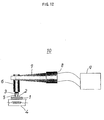
- a mounting apparatus 20 of an electronic part comprises an ultrasonic vibration generating device 8, a horn 7, a collet tool 6 a substrate conductor heating unit (not shown), a control unit 9, and a laser displacement meter 11 attached to the control unit which acts as a distance measuring device for monitoring the distance of the semiconductor chip 3 attached to the collet tool 6 with respect to a substrate conductor (not shown), the substrate conductor also being connected to the control unit 9.
- the semiconductor chip 3 is mounted to the substrate conductor by the mounting apparatus 20 according to the following steps:
- a predetermined weight R of about 0.1 to 200 grams/l bamp which is suitably set according to the material, shape, size, number and the like of the bumps 5 (normally several hundred gw to 1kgw), is applied for generally about 10-10,000 msec.
- the application of weight R causes slight crushing and sinking of the bumps 5, into the electrodes 2. This weight is termed the first stage sinking amount H1.
- the predetermined weight R and an ultrasonic vibration US are applied for a predetermined time T2, generally about 50-10,000 msec, so that the electrode of the semiconductor chip 3 is joined to the electrodes 2 of the substrate conductor 1 by ultrasonic wave and thermocompression bonding of the bumps 5.
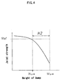
- the head 12 of the collet tool is separated from the semiconductor chip 3 so as to rise, and the sinking amount of the bumps 5, termed the second stage sinking amount H2, caused by the application of the predetermined weight R and ultrasonic vibration US, is monitored by the laser displacement meter 11 (distance measuring device) shown in Fig. 1, and a judgment is made as to whether or not the sinking amount H2 of the bumps 5 is in a desired range. Specifically, a judgment is made as to whether the joint obtained by the ultrasonic wave and thermocompression bonding connection utilizing the flip-chip bonding system is defective or non-defective.
- the amount of compression i.e., the sinking amount H2
- the amount of compression i.e., the sinking amount H2
- the joint strength between the electrode of the semiconductor chip 3 and the electrodes 2 of the substrate conductor 1 by means of the bumps 5 satisfy a graphical relationship, as shown in Fig. 4.
- thermosonic bonding an almost uniform bonding is effected at a boundary between a semiconductor electrode and a bump.
- a bonding strength for each unit area is determined by the materials the semiconductor electrode and the bump are made of. It can be said that if strengths are equal, then bonding areas are equal. Furthermore, if a bump is compressed by a load and ultrasonic vibration, the bonding area is increased.
- the compression of the bumps that is the sinking amounts thereof, and bonding areas are uniquely determined. And if bonding areas are equal to each other, then bonding strengths are also equal to each other. Hence, inspection of the joint formed between the semiconductor chip and the substrate conductor can be performed by measuring the amount of compression of the bump (the sinking amount).
- a standard of judgment is previously set so that when the joint connection between the bumps (Au bumps) 5 and the electrodes 2 is not less the 50 gw, the joint is non-defective, and when smaller than 50 gw, the joint is defective.
- the sinking amount H2 at the second stage, as shown in Fig. 3(c) is not less than 25 ⁇ m, the joint is defective.
- a judgment is made by the control unit 9 as to whether the joint is defective or non-defective based on monitored data from the laser displacement meter 11, also referred to herein as the distance measuring device.
- a product whose joint strength is not more than 25 gw is defective, it is treated as a defective product or, if the desired sinking amount H2 can be obtained by again applying a ultrasonic wave, a non-defective joint can be produced. Therefore, a defective joint formed on the first attempt does not necessarily influence production steps thereafter, and yield of non-defective products can be improved.
- the mounting method is a method for monitoring only the sinking amount H2 at the second stage of the method of the present invention, as shown in Fig. 3(c), and may be enough to judge whether the joint is defective or non-defective.
- the sinking amount H1 of the bumps at the first stage where the predetermined weight of about 0.1 to 200 grams/l bamp is applied for the predetermined time T1 (generally about 10-10,000 msec, but usually predetermined on the order of 100 msec) just when the bumps 5 come into contact with the mating electrodes 2, and the sinking amount H2 of the bumps at the second stage, where in addition to the application of predetermined weight R, ultrasonic vibration US is applied for the predetermined time T2 (generally about 50 to 10,000, but usually predetermined in the range of about 1000 to 2000 msec) are individually monitored by the laser displacement meter 11 acting as a distance measuring device.
- the sinking amount H1 of the bumps 5 at the stage of the process shown in Fig. 3(b) at the time when the predetermined weight R is applied for the predetermined time T1, deviates from a range of set values, the bumps are deemed abnormal, and slipping of the bumps may occur. For this reason, a judgment can be made at a stage before the joint is made as to whether the bumps are defective or non-defective. To make such a judgment, When the sinking amount H1 at the first stage and the sinking amount H2 at the second stage are separately monitored and evaluated, the defectiveness or non-defectiveness of the joint can be judged with a high degree of accuracy.
- the distance measuring device for successively monitoring the height of the head 12 i.e., monitoring the siding amounts H1 and H2 in the above embodiment
- devices other the the laser displacement meter 11 may be used.
- a counter for counting a pulse number of a pulse motor may be used.
- grids G as degrees are formed on a side surface of the collet tool 6, which retains the electronic part and is joined to the substrate conductor in every 1 ⁇ m, and the number of grids passing a grid sensor 31 during application of the ultrasonic vibration US are counted by a light laser or the like based on the time when the semiconductor chip 3 on the head of the forward end of the collet tool comes in contact with the bumps, so that the sinking amount H2 of the chip at the second stage can be obtained.
- the grids G may be formed by a magnetic material and, if so, the counting may be executed by a magnetic sensor.
- the grids may also be provided on the forward end of the horn 7.
- measuring means utilizing measurement of capacitance may be used as another means for measuring the distance of the head with respect to the substrate conductor.
- a flat type electrode B may be provided 1 mm below the bottom dead center of the horn 7, and capacitance C between the flat type electrode B and the horn 7, which is made of metal, is measured. Since the capacitance C is determined by the distance S between the horn 7 and the flat electrode B, the sinking amount of the semiconductor chip 3 is detected by measuring the capacitance C by a capacitance detecting meter. This measurement of capacitance allows judgement of the defectiveness or non-defectiveness of the joint.
- a coil horn can be directly mounted as the horn 7, and the distance between the coil horn and the substrate conductor can be obtained by an inductance component of the coil horn.
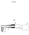
- Mounting apparatus 30 as shown in Fig. 7, includes, in addition to the components of the conventional mounting apparatus 10 shown in Fig. 12, a vibration measuring device 21 for monitoring a vibrating state of the semiconductor chip 3 or the bumps 5, which is connected with the control unit 9 of the electronic part.
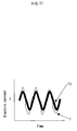
- a vibration waveform W for example, of the semiconductor chip 3 at the time of the mounting is measured and it is compared with a preset reference waveform W0, as shown in Fig. 8, and the joint is inspected to determine whether it is defective or non-defective by making a judgment as to whether or not the ultrasonic vibration US is applied normally.
- a laser Doppler vibration meter 22 is provided as the vibration measuring device 21.
- a laser beam of the laser Doppler vibration meter 22 is directed at the semiconductor chip 3, and the vibrating state of the semiconductor chip 3 at the time of the mounting (amplitude and vibrating speed) is monitored as a waveform.
- the obtained vibration waveform W is compared with the reference waveform W0 by the control unit 9, so that a judgment can be made as to whether or not the ultrasonic vibration US is normally applied to the bumps 5, and when the vibration waveform W deviates from the allowable range of the reference waveform W0, the joint is deemed defective.
- the vibration waveform W is decomposed according to frequency by FFT (fast Fourier transform), and spectrums W1 and W2 are respectively compared with corresponding reference wave spectrums W01 and W02 of the reference waveform W0 so that a comparison and judgment can be quantitatively made.
- FFT fast Fourier transform
- Mounting apparatus 40 shown in Fig. 10, includes, in addition to the components of the conventional mounting apparatus 10 shown in Fig. 12, a measuring device for monitoring an electric current i applied to the ultrasonic vibration generating device (piezoelectric element) 8, which is connected to the control unit 9, so as to be positioned therein.
- a waveform of the measured electric current i is compared with a preset reference electric current waveform i0, as shown in Fig. 11, and the bump is inspected and judged to be defective or non-defective by making a judgment as to whether or not the ultrasonic vibration US is applied normally to the bumps 5.
- a voltage V may be applied to a piezoelectric crystal element, as decribed above using an electric current i, and the change in the voltage measured to determine the waveform. Then, this waveform can be compared with a reference waveform, as described above with an electric current i.
- the aforementioned embodiment referred mainly to the mounting of semiconductor chips onto substrates but, needless to say, it can be applied to all electronic parts which can be flip-chip bonded by the ultrasonic wave and thermocompression bonding method.
- the mounting method and mounting apparatus of the electronic part since when the mounting height, vibrational state and electric current of the ultrasonic vibration generating device (piezoelectric element) are monitored and compared with the reference values and reference waveforms, a judgment can be made as to whether or not the joint state and ultrasonic vibrating state of the electronic part by means of the bumps are normal simultaneously with the mounting. If any abnormality is measured or detected, the following countermeasures may be taken:
- the above mounting method and mounting apparatus have the desirable quality in that the joint can, be judged as defective or non-defective, and the product can be reproduced.
Landscapes
- Engineering & Computer Science (AREA)
- Mechanical Engineering (AREA)
- Wire Bonding (AREA)
- Length Measuring Devices With Unspecified Measuring Means (AREA)
- Electric Connection Of Electric Components To Printed Circuits (AREA)
Priority Applications (2)
| Application Number | Priority Date | Filing Date | Title |
|---|---|---|---|
| EP04017117A EP1486790B1 (fr) | 1998-04-09 | 1999-04-07 | Procédé et appareillage pour le montage "flip-chip" de composants électroniques |
| EP04017118A EP1469319B1 (fr) | 1998-04-09 | 1999-04-07 | Procédé et appareillage pour le montage "flip-chip" de composants électroniques |
Applications Claiming Priority (2)
| Application Number | Priority Date | Filing Date | Title |
|---|---|---|---|
| JP09733598A JP3176580B2 (ja) | 1998-04-09 | 1998-04-09 | 電子部品の実装方法及び実装装置 |
| JP9733598 | 1998-04-09 |
Related Child Applications (2)
| Application Number | Title | Priority Date | Filing Date |
|---|---|---|---|
| EP04017118A Division EP1469319B1 (fr) | 1998-04-09 | 1999-04-07 | Procédé et appareillage pour le montage "flip-chip" de composants électroniques |
| EP04017117A Division EP1486790B1 (fr) | 1998-04-09 | 1999-04-07 | Procédé et appareillage pour le montage "flip-chip" de composants électroniques |
Publications (3)
| Publication Number | Publication Date |
|---|---|
| EP0949670A2 true EP0949670A2 (fr) | 1999-10-13 |
| EP0949670A3 EP0949670A3 (fr) | 1999-11-17 |
| EP0949670B1 EP0949670B1 (fr) | 2005-06-22 |
Family
ID=14189624
Family Applications (3)
| Application Number | Title | Priority Date | Filing Date |
|---|---|---|---|
| EP04017117A Expired - Lifetime EP1486790B1 (fr) | 1998-04-09 | 1999-04-07 | Procédé et appareillage pour le montage "flip-chip" de composants électroniques |
| EP04017118A Expired - Lifetime EP1469319B1 (fr) | 1998-04-09 | 1999-04-07 | Procédé et appareillage pour le montage "flip-chip" de composants électroniques |
| EP99106876A Expired - Lifetime EP0949670B1 (fr) | 1998-04-09 | 1999-04-07 | Procédé et appareillage pour le montage "flip-chip" de composants électroniques |
Family Applications Before (2)
| Application Number | Title | Priority Date | Filing Date |
|---|---|---|---|
| EP04017117A Expired - Lifetime EP1486790B1 (fr) | 1998-04-09 | 1999-04-07 | Procédé et appareillage pour le montage "flip-chip" de composants électroniques |
| EP04017118A Expired - Lifetime EP1469319B1 (fr) | 1998-04-09 | 1999-04-07 | Procédé et appareillage pour le montage "flip-chip" de composants électroniques |
Country Status (5)
| Country | Link |
|---|---|
| US (1) | US6543668B1 (fr) |
| EP (3) | EP1486790B1 (fr) |
| JP (1) | JP3176580B2 (fr) |
| DE (3) | DE69925878T2 (fr) |
| TW (1) | TW526688B (fr) |
Cited By (6)
| Publication number | Priority date | Publication date | Assignee | Title |
|---|---|---|---|---|
| EP1295328A4 (fr) * | 2000-03-10 | 2010-01-06 | Chippac Inc | Boitier du type puce a bosses sur grille de connexion et procede correspondant |
| CN1300180B (zh) * | 1999-11-24 | 2010-09-29 | 欧姆龙株式会社 | 芯片安装、电路板、数据载体及制造方法和电子元件组件 |
| US20130270230A1 (en) * | 2012-04-17 | 2013-10-17 | Yiu Ming Cheung | Thermal compression bonding of semiconductor chips |
| CN104708157A (zh) * | 2013-12-17 | 2015-06-17 | 库利克和索夫工业公司 | 用于焊接半导体元件的焊接机的操作方法和焊接机 |
| US20220310551A1 (en) * | 2021-03-24 | 2022-09-29 | Samsung Electronics Co., Ltd. | Semiconductor manufacturing apparatus |
| IT202300003024A1 (it) * | 2023-02-22 | 2024-08-22 | Vodafone Automotive S P A | Un metodo per valutare l'impatto della saldatura ultrasonica su un pezzo durante un processo di pre-produzione e un’apparecchiatura per lo stesso |
Families Citing this family (55)
| Publication number | Priority date | Publication date | Assignee | Title |
|---|---|---|---|---|
| DE10020374A1 (de) * | 1999-07-02 | 2001-01-25 | Fujitsu Ltd | Kopfbaugruppe einer Plattenvorrichtung mit einem Kopf-IC-Chip, der durch Ultraschallbonden an eine Aufhängung montiert ist |
| JP3506233B2 (ja) * | 2000-06-28 | 2004-03-15 | シャープ株式会社 | 半導体装置及びその製造方法 |
| JP2004047944A (ja) * | 2002-05-22 | 2004-02-12 | Nec Corp | 接合装置および接合の良否判別方法を有する接合方法 |
| JP4507582B2 (ja) * | 2003-12-12 | 2010-07-21 | パナソニック株式会社 | バンプ付電子部品の実装方法 |
| US7017422B2 (en) * | 2004-04-02 | 2006-03-28 | Luna Innovations Incorporated | Bond testing system, method, and apparatus |
| JP2005340780A (ja) * | 2004-04-27 | 2005-12-08 | Matsushita Electric Ind Co Ltd | 電子部品装着装置および電子部品装着方法 |
| KR101260981B1 (ko) | 2004-06-04 | 2013-05-10 | 더 보오드 오브 트러스티스 오브 더 유니버시티 오브 일리노이즈 | 인쇄가능한 반도체소자들의 제조 및 조립방법과 장치 |
| JP4529759B2 (ja) * | 2005-03-29 | 2010-08-25 | パナソニック株式会社 | 電子部品装着装置および電子部品装着方法 |
| EP1897119B1 (fr) * | 2005-06-13 | 2010-03-17 | Panasonic Corporation | Appareil de liaison de dispositif semi-conducteur et procédé de liaison d'un dispositif semi-conducteur l'utilisant |
| KR100662820B1 (ko) | 2005-09-27 | 2006-12-28 | 삼성테크윈 주식회사 | 플립칩 본더 |
| WO2008102592A1 (fr) * | 2007-02-22 | 2008-08-28 | Shibaura Mechatronics Corporation | Appareil et procédé pour le montage d'un composant électronique |
| CN101652845B (zh) * | 2007-04-27 | 2012-02-01 | 松下电器产业株式会社 | 电子元器件安装装置及电子元器件安装方法 |
| US20090155958A1 (en) * | 2007-12-13 | 2009-06-18 | Boris Kolodin | Robust die bonding process for led dies |
| JP4924480B2 (ja) * | 2008-03-03 | 2012-04-25 | 日本電気株式会社 | 半導体装置の製造方法および装置 |
| US20090289101A1 (en) * | 2008-05-23 | 2009-11-26 | Yong Du | Method for ball grid array (bga) solder attach for surface mount |
| JP2010153672A (ja) * | 2008-12-26 | 2010-07-08 | Nec Corp | 半導体装置の製造装置およびその製造方法 |
| US8939346B2 (en) * | 2011-02-15 | 2015-01-27 | International Business Machines Corporation | Methods and systems involving soldering |
| JP5877645B2 (ja) * | 2011-02-15 | 2016-03-08 | 東レエンジニアリング株式会社 | 実装方法および実装装置 |
| JP5686321B2 (ja) * | 2011-03-31 | 2015-03-18 | Jukiオートメーションシステムズ株式会社 | 実装装置、電子部品の実装方法及び基板の製造方法 |
| US8870051B2 (en) * | 2012-05-03 | 2014-10-28 | International Business Machines Corporation | Flip chip assembly apparatus employing a warpage-suppressor assembly |
| JP5878843B2 (ja) * | 2012-08-08 | 2016-03-08 | 日本特殊陶業株式会社 | スパークプラグの製造方法 |
| DE102013204590B3 (de) * | 2013-03-15 | 2014-07-24 | Asm Assembly Systems Gmbh & Co. Kg | Erkennen eines schwingenden Bauelementeträgers während einer Bestückung mit Bauelementen |
| US9575560B2 (en) | 2014-06-03 | 2017-02-21 | Google Inc. | Radar-based gesture-recognition through a wearable device |
| US9921660B2 (en) | 2014-08-07 | 2018-03-20 | Google Llc | Radar-based gesture recognition |
| US9811164B2 (en) | 2014-08-07 | 2017-11-07 | Google Inc. | Radar-based gesture sensing and data transmission |
| US10268321B2 (en) | 2014-08-15 | 2019-04-23 | Google Llc | Interactive textiles within hard objects |
| US9588625B2 (en) | 2014-08-15 | 2017-03-07 | Google Inc. | Interactive textiles |
| US9778749B2 (en) | 2014-08-22 | 2017-10-03 | Google Inc. | Occluded gesture recognition |
| US11169988B2 (en) | 2014-08-22 | 2021-11-09 | Google Llc | Radar recognition-aided search |
| US9600080B2 (en) | 2014-10-02 | 2017-03-21 | Google Inc. | Non-line-of-sight radar-based gesture recognition |
| US10319619B2 (en) * | 2014-12-05 | 2019-06-11 | Samsung Electronics Co., Ltd. | Equipment for manufacturing semiconductor devices and method for use of same for manufacturing semiconductor package components |
| US10016162B1 (en) | 2015-03-23 | 2018-07-10 | Google Llc | In-ear health monitoring |
| US9983747B2 (en) | 2015-03-26 | 2018-05-29 | Google Llc | Two-layer interactive textiles |
| US9847313B2 (en) * | 2015-04-24 | 2017-12-19 | Kulicke And Soffa Industries, Inc. | Thermocompression bonders, methods of operating thermocompression bonders, and horizontal scrub motions in thermocompression bonding |
| CN107466389B (zh) | 2015-04-30 | 2021-02-12 | 谷歌有限责任公司 | 用于确定类型不可知的rf信号表示的方法和装置 |
| EP3289434A1 (fr) | 2015-04-30 | 2018-03-07 | Google LLC | Reconnaissance de gestes fondée sur un radar à champ large |
| EP3289432B1 (fr) | 2015-04-30 | 2019-06-12 | Google LLC | Suivi de micro-mouvements sur la base de rf pour suivi et reconnaissance de gestes |
| JP5930563B2 (ja) * | 2015-05-14 | 2016-06-08 | 東レエンジニアリング株式会社 | 実装方法および実装装置 |
| US10088908B1 (en) | 2015-05-27 | 2018-10-02 | Google Llc | Gesture detection and interactions |
| US9693592B2 (en) * | 2015-05-27 | 2017-07-04 | Google Inc. | Attaching electronic components to interactive textiles |
| US9929121B2 (en) * | 2015-08-31 | 2018-03-27 | Kulicke And Soffa Industries, Inc. | Bonding machines for bonding semiconductor elements, methods of operating bonding machines, and techniques for improving UPH on such bonding machines |
| US10817065B1 (en) | 2015-10-06 | 2020-10-27 | Google Llc | Gesture recognition using multiple antenna |
| WO2017079484A1 (fr) | 2015-11-04 | 2017-05-11 | Google Inc. | Connecteurs pour connecter des éléments électroniques incorporés dans des vêtements à des dispositifs externes |
| KR102427644B1 (ko) | 2015-11-16 | 2022-08-02 | 삼성전자주식회사 | 광원 모듈, 광원 모듈의 제조방법 및 이를 포함하는 디스플레이 장치 |
| US10492302B2 (en) | 2016-05-03 | 2019-11-26 | Google Llc | Connecting an electronic component to an interactive textile |
| WO2017200570A1 (fr) | 2016-05-16 | 2017-11-23 | Google Llc | Objet interactif à modules électroniques multiples |
| US10579150B2 (en) | 2016-12-05 | 2020-03-03 | Google Llc | Concurrent detection of absolute distance and relative movement for sensing action gestures |
| KR102242248B1 (ko) * | 2017-05-02 | 2021-04-20 | 주식회사 엘지화학 | 이차전지의 용접 검사장치 및 검사방법 |
| DE102019109262B4 (de) * | 2019-04-09 | 2025-11-20 | Lisa Dräxlmaier GmbH | VORRICHTUNG UND VERFAHREN ZUM BESTIMMEN EINES ZUSTANDS EINES ULTRASCHALLSCHWEIßPROZESSES |
| KR102814631B1 (ko) * | 2019-04-23 | 2025-05-29 | 삼성디스플레이 주식회사 | 표시 장치의 제조 방법 |
| WO2022222148A1 (fr) * | 2021-04-23 | 2022-10-27 | 重庆康佳光电技术研究院有限公司 | Procédé et appareil de transfert de puce, fond de panier d'affichage et dispositif d'affichage |
| TWI856332B (zh) * | 2022-06-16 | 2024-09-21 | 日商新川股份有限公司 | 超音波複合振動裝置及半導體裝置的製造裝置 |
| KR102537573B1 (ko) * | 2023-01-27 | 2023-05-30 | 주식회사 엠아이이큅먼트코리아 | 플립 칩 레이저 본딩장치의 본딩 툴 |
| DE102023110696A1 (de) * | 2023-04-26 | 2024-10-31 | Pac Tech - Packaging Technologies Gmbh | Bondkopf und Bondvorrichtung |
| TW202548965A (zh) * | 2024-04-03 | 2025-12-16 | 日商松下知識產權經營股份有限公司 | 接合良否判定系統及接合良否判定方法 |
Family Cites Families (25)
| Publication number | Priority date | Publication date | Assignee | Title |
|---|---|---|---|---|
| US3596050A (en) * | 1970-05-05 | 1971-07-27 | Union Carbide Corp | Automatic torch height control |
| SU1128201A1 (ru) * | 1983-04-07 | 1984-12-07 | Предприятие П/Я Р-6668 | Устройство контрол па ных соединений |
| DD217088A1 (de) * | 1983-08-29 | 1985-01-02 | Adw Ddr | Verfahren zur einstellung eines optimalen arbeitsbereiches beim ultraschallbonden |
| JP2506958B2 (ja) * | 1988-07-22 | 1996-06-12 | 松下電器産業株式会社 | ワイヤボンディング装置 |
| CA1285661C (fr) * | 1988-08-19 | 1991-07-02 | Randy Tsang | Mesurage visuel automatique du placement de dispositifs ensurface d'un substrat |
| US5176140A (en) * | 1989-08-14 | 1993-01-05 | Olympus Optical Co., Ltd. | Ultrasonic probe |
| JPH03125447A (ja) * | 1989-10-11 | 1991-05-28 | Toshiba Corp | ボンディング装置 |
| US4998664A (en) * | 1989-12-22 | 1991-03-12 | Hughes Aircraft Company | Bond signature analyzer |
| EP0498936B1 (fr) * | 1991-02-15 | 1995-01-25 | Esec Sa | Procédé et dispositif de mesure de l'amplitude d'oscillation d'un transducteur d'énergie |
| JP2953116B2 (ja) * | 1991-06-11 | 1999-09-27 | 日本電気株式会社 | ワイヤーボンディング装置 |
| JP3007195B2 (ja) * | 1991-09-18 | 2000-02-07 | 株式会社日立製作所 | ボンディング装置およびボンディング部検査装置 |
| JP2705423B2 (ja) * | 1992-01-24 | 1998-01-28 | 株式会社日立製作所 | 超音波接合装置及び品質モニタリング方法 |
| US5230458A (en) * | 1992-06-23 | 1993-07-27 | National Semiconductor Corp. | Interconnect formation utilizing real-time feedback |
| JPH06210475A (ja) * | 1993-01-14 | 1994-08-02 | Fanuc Ltd | レーザロボットのハイトセンサ装置 |
| JP3194553B2 (ja) * | 1993-08-13 | 2001-07-30 | 富士通株式会社 | 半導体装置の製造方法 |
| US5341979A (en) * | 1993-09-03 | 1994-08-30 | Motorola, Inc. | Method of bonding a semiconductor substrate to a support substrate and structure therefore |
| JPH07115109A (ja) * | 1993-10-15 | 1995-05-02 | Nec Corp | フリップチップボンディング方法及び装置 |
| US5446261A (en) * | 1993-10-26 | 1995-08-29 | International Business Machines Corporation | Solder application system using helix to control solder meniscus |
| US5493775A (en) * | 1994-01-21 | 1996-02-27 | International Business Machines Corporation | Pressure contact open-circuit detector |
| US5427301A (en) * | 1994-05-06 | 1995-06-27 | Ford Motor Company | Ultrasonic flip chip process and apparatus |
| JPH0817876A (ja) * | 1994-06-29 | 1996-01-19 | Fujitsu Ltd | ワイヤーボンダー |
| JPH0951007A (ja) * | 1995-08-09 | 1997-02-18 | Mitsubishi Electric Corp | ダイボンド装置および半導体装置の製造方法 |
| US5992729A (en) * | 1996-10-02 | 1999-11-30 | Mcnc | Tacking processes and systems for soldering |
| JP3330037B2 (ja) * | 1996-11-29 | 2002-09-30 | 富士通株式会社 | チップ部品の接合方法および装置 |
| EP1010492B1 (fr) * | 1998-12-10 | 2004-09-01 | Ultex Corporation | Procédé de soudage par vibration ultrasonique |
-
1998
- 1998-04-09 JP JP09733598A patent/JP3176580B2/ja not_active Expired - Lifetime
-
1999
- 1999-03-30 TW TW088105036A patent/TW526688B/zh not_active IP Right Cessation
- 1999-04-07 DE DE69925878T patent/DE69925878T2/de not_active Expired - Lifetime
- 1999-04-07 US US09/287,639 patent/US6543668B1/en not_active Expired - Lifetime
- 1999-04-07 EP EP04017117A patent/EP1486790B1/fr not_active Expired - Lifetime
- 1999-04-07 DE DE69930433T patent/DE69930433T2/de not_active Expired - Lifetime
- 1999-04-07 EP EP04017118A patent/EP1469319B1/fr not_active Expired - Lifetime
- 1999-04-07 EP EP99106876A patent/EP0949670B1/fr not_active Expired - Lifetime
- 1999-04-07 DE DE69928457T patent/DE69928457T2/de not_active Expired - Lifetime
Cited By (12)
| Publication number | Priority date | Publication date | Assignee | Title |
|---|---|---|---|---|
| CN1300180B (zh) * | 1999-11-24 | 2010-09-29 | 欧姆龙株式会社 | 芯片安装、电路板、数据载体及制造方法和电子元件组件 |
| EP1295328A4 (fr) * | 2000-03-10 | 2010-01-06 | Chippac Inc | Boitier du type puce a bosses sur grille de connexion et procede correspondant |
| US20130270230A1 (en) * | 2012-04-17 | 2013-10-17 | Yiu Ming Cheung | Thermal compression bonding of semiconductor chips |
| US8967452B2 (en) * | 2012-04-17 | 2015-03-03 | Asm Technology Singapore Pte Ltd | Thermal compression bonding of semiconductor chips |
| CN104708157A (zh) * | 2013-12-17 | 2015-06-17 | 库利克和索夫工业公司 | 用于焊接半导体元件的焊接机的操作方法和焊接机 |
| US20150171049A1 (en) * | 2013-12-17 | 2015-06-18 | Kulicke And Soffa Industries, Inc. | Methods of operating bonding machines for bonding semiconductor elements, and bonding machines |
| US9165902B2 (en) * | 2013-12-17 | 2015-10-20 | Kulicke And Soffa Industries, Inc. | Methods of operating bonding machines for bonding semiconductor elements, and bonding machines |
| US9478516B2 (en) | 2013-12-17 | 2016-10-25 | Kulicke And Soffa Industries, Inc. | Methods of operating bonding machines for bonding semiconductor elements, and bonding machines |
| US20220310551A1 (en) * | 2021-03-24 | 2022-09-29 | Samsung Electronics Co., Ltd. | Semiconductor manufacturing apparatus |
| US11658147B2 (en) * | 2021-03-24 | 2023-05-23 | Samsung Electronics Co., Ltd. | Semiconductor manufacturing apparatus |
| IT202300003024A1 (it) * | 2023-02-22 | 2024-08-22 | Vodafone Automotive S P A | Un metodo per valutare l'impatto della saldatura ultrasonica su un pezzo durante un processo di pre-produzione e un’apparecchiatura per lo stesso |
| WO2024175470A1 (fr) * | 2023-02-22 | 2024-08-29 | Vodafone Automotive S.P.A | Procédé d'évaluation de l'impact d'un soudage par ultrasons sur une pièce pendant un processus de pré-production et appareil associé |
Also Published As
| Publication number | Publication date |
|---|---|
| DE69928457D1 (de) | 2005-12-22 |
| JPH11297761A (ja) | 1999-10-29 |
| DE69928457T2 (de) | 2006-07-27 |
| JP3176580B2 (ja) | 2001-06-18 |
| EP1469319B1 (fr) | 2006-03-22 |
| US6543668B1 (en) | 2003-04-08 |
| DE69925878T2 (de) | 2006-05-11 |
| EP1486790A1 (fr) | 2004-12-15 |
| TW526688B (en) | 2003-04-01 |
| DE69930433T2 (de) | 2006-12-07 |
| EP0949670B1 (fr) | 2005-06-22 |
| EP1469319A1 (fr) | 2004-10-20 |
| DE69930433D1 (de) | 2006-05-11 |
| EP0949670A3 (fr) | 1999-11-17 |
| DE69925878D1 (de) | 2005-07-28 |
| EP1486790B1 (fr) | 2005-11-16 |
Similar Documents
| Publication | Publication Date | Title |
|---|---|---|
| US6543668B1 (en) | Mounting method and mounting apparatus for electronic part | |
| JP3007195B2 (ja) | ボンディング装置およびボンディング部検査装置 | |
| Or et al. | Ultrasonic wire-bond quality monitoring using piezoelectric sensor | |
| US4854494A (en) | Monitoring bond parameters during the bonding process | |
| US4373653A (en) | Method and apparatus for ultrasonic bonding | |
| US7492449B2 (en) | Inspection systems and methods | |
| Or et al. | Dynamics of an ultrasonic transducer used for wire bonding | |
| US5533398A (en) | Method and apparatus for testing lead connections of electronic components | |
| US5201841A (en) | Thermal delay non-destructive bond integrity inspection | |
| US6962281B2 (en) | Bonding apparatus and bonding method having process for judging bonding state | |
| Mayer et al. | In situ ultrasonic stress measurements during ball bonding using integrated piezoresistive microsensors | |
| US6929168B2 (en) | Method for determining optimum bonding parameters for bonding with a wire bonder | |
| US5493775A (en) | Pressure contact open-circuit detector | |
| Rodwell et al. | Quality control in ultrasonic wire bonding | |
| JP2708222B2 (ja) | ボンディング装置 | |
| KR102684125B1 (ko) | 적층형 반도체의 잠재 불량 스크린 장치 및 그 방법 | |
| US7080771B2 (en) | Method for checking the quality of a wedge bond | |
| Harman | Acoustic-emission-monitored tests for TAB inner lead bond quality | |
| JP3573113B2 (ja) | ボンディングダメージの計測装置および計測方法 | |
| JPH056661Y2 (fr) | ||
| JP2001127112A (ja) | 半導体チップボンディング方法および装置 | |
| JPH0699289A (ja) | 超音波接合方法 | |
| Arndt et al. | Manufacturing and Characterization of Piezoelectric Force Sensor Arrays for Investigation of Ultrasonic Wire Bonding | |
| Seppänen et al. | Ultrasonic Wire Bond Outlier Classification | |
| JP3573112B2 (ja) | ボンディングダメージの計測用基板 |
Legal Events
| Date | Code | Title | Description |
|---|---|---|---|
| PUAI | Public reference made under article 153(3) epc to a published international application that has entered the european phase |
Free format text: ORIGINAL CODE: 0009012 |
|
| PUAL | Search report despatched |
Free format text: ORIGINAL CODE: 0009013 |
|
| AK | Designated contracting states |
Kind code of ref document: A2 Designated state(s): DE FI GB |
|
| AX | Request for extension of the european patent |
Free format text: AL;LT;LV;MK;RO;SI |
|
| RIC1 | Information provided on ipc code assigned before grant |
Free format text: 6G 01R 31/04 A, 6H 01L 21/60 B, 6H 01L 21/607 B, 6H 01L 21/603 B, 6H 01L 21/66 B |
|
| RTI1 | Title (correction) |
Free format text: FLIP-CHIP MOUNTING METHOD AND MOUNTING APPARATUS OF ELECTRONIC PART |
|
| AK | Designated contracting states |
Kind code of ref document: A3 Designated state(s): AT BE CH CY DE DK ES FI FR GB GR IE IT LI LU MC NL PT SE |
|
| AX | Request for extension of the european patent |
Free format text: AL;LT;LV;MK;RO;SI |
|
| RTI1 | Title (correction) |
Free format text: FLIP-CHIP MOUNTING METHOD AND MOUNTING APPARATUS OF ELECTRONIC PART |
|
| 17P | Request for examination filed |
Effective date: 20000112 |
|
| AKX | Designation fees paid |
Free format text: DE FI GB |
|
| 17Q | First examination report despatched |
Effective date: 20030410 |
|
| GRAP | Despatch of communication of intention to grant a patent |
Free format text: ORIGINAL CODE: EPIDOSNIGR1 |
|
| GRAS | Grant fee paid |
Free format text: ORIGINAL CODE: EPIDOSNIGR3 |
|
| GRAA | (expected) grant |
Free format text: ORIGINAL CODE: 0009210 |
|
| AK | Designated contracting states |
Kind code of ref document: B1 Designated state(s): DE FI GB |
|
| REG | Reference to a national code |
Ref country code: GB Ref legal event code: FG4D |
|
| REF | Corresponds to: |
Ref document number: 69925878 Country of ref document: DE Date of ref document: 20050728 Kind code of ref document: P |
|
| PLBE | No opposition filed within time limit |
Free format text: ORIGINAL CODE: 0009261 |
|
| STAA | Information on the status of an ep patent application or granted ep patent |
Free format text: STATUS: NO OPPOSITION FILED WITHIN TIME LIMIT |
|
| 26N | No opposition filed |
Effective date: 20060323 |
|
| PGFP | Annual fee paid to national office [announced via postgrant information from national office to epo] |
Ref country code: GB Payment date: 20180329 Year of fee payment: 20 |
|
| PGFP | Annual fee paid to national office [announced via postgrant information from national office to epo] |
Ref country code: DE Payment date: 20180327 Year of fee payment: 20 Ref country code: FI Payment date: 20180410 Year of fee payment: 20 |
|
| REG | Reference to a national code |
Ref country code: DE Ref legal event code: R071 Ref document number: 69925878 Country of ref document: DE |
|
| REG | Reference to a national code |
Ref country code: GB Ref legal event code: PE20 Expiry date: 20190406 |
|
| PG25 | Lapsed in a contracting state [announced via postgrant information from national office to epo] |
Ref country code: GB Free format text: LAPSE BECAUSE OF EXPIRATION OF PROTECTION Effective date: 20190406 |