EP0949721A1 - Einsteckbarer und verriegelbarer einpoliger Steckverbinder - Google Patents
Einsteckbarer und verriegelbarer einpoliger Steckverbinder Download PDFInfo
- Publication number
- EP0949721A1 EP0949721A1 EP99104344A EP99104344A EP0949721A1 EP 0949721 A1 EP0949721 A1 EP 0949721A1 EP 99104344 A EP99104344 A EP 99104344A EP 99104344 A EP99104344 A EP 99104344A EP 0949721 A1 EP0949721 A1 EP 0949721A1
- Authority
- EP
- European Patent Office
- Prior art keywords
- connector
- locking element
- mating
- camming
- locking
- Prior art date
- Legal status (The legal status is an assumption and is not a legal conclusion. Google has not performed a legal analysis and makes no representation as to the accuracy of the status listed.)
- Granted
Links
- 230000005404 monopole Effects 0.000 title abstract description 12
- 230000013011 mating Effects 0.000 claims abstract description 62
- 230000008878 coupling Effects 0.000 claims abstract description 19
- 238000010168 coupling process Methods 0.000 claims abstract description 19
- 238000005859 coupling reaction Methods 0.000 claims abstract description 19
- 239000004020 conductor Substances 0.000 claims abstract description 7
- 230000000295 complement effect Effects 0.000 claims description 30
- 230000007704 transition Effects 0.000 claims description 5
- 238000002788 crimping Methods 0.000 claims description 4
- 239000000463 material Substances 0.000 claims description 4
- 239000002184 metal Substances 0.000 claims description 3
- 230000008646 thermal stress Effects 0.000 description 2
- 230000000694 effects Effects 0.000 description 1
- 230000014759 maintenance of location Effects 0.000 description 1
- 238000004519 manufacturing process Methods 0.000 description 1
- 230000005405 multipole Effects 0.000 description 1
- 230000000717 retained effect Effects 0.000 description 1
Images


Classifications
-
- H—ELECTRICITY
- H01—ELECTRIC ELEMENTS
- H01R—ELECTRICALLY-CONDUCTIVE CONNECTIONS; STRUCTURAL ASSOCIATIONS OF A PLURALITY OF MUTUALLY-INSULATED ELECTRICAL CONNECTING ELEMENTS; COUPLING DEVICES; CURRENT COLLECTORS
- H01R24/00—Two-part coupling devices, or either of their cooperating parts, characterised by their overall structure
- H01R24/28—Coupling parts carrying pins, blades or analogous contacts and secured only to wire or cable
-
- H—ELECTRICITY
- H01—ELECTRIC ELEMENTS
- H01R—ELECTRICALLY-CONDUCTIVE CONNECTIONS; STRUCTURAL ASSOCIATIONS OF A PLURALITY OF MUTUALLY-INSULATED ELECTRICAL CONNECTING ELEMENTS; COUPLING DEVICES; CURRENT COLLECTORS
- H01R13/00—Details of coupling devices of the kinds covered by groups H01R12/70 or H01R24/00 - H01R33/00
- H01R13/02—Contact members
- H01R13/20—Pins, blades, or sockets shaped, or provided with separate member, to retain co-operating parts together
- H01R13/213—Pins, blades, or sockets shaped, or provided with separate member, to retain co-operating parts together by bayonet connection
-
- H—ELECTRICITY
- H01—ELECTRIC ELEMENTS
- H01R—ELECTRICALLY-CONDUCTIVE CONNECTIONS; STRUCTURAL ASSOCIATIONS OF A PLURALITY OF MUTUALLY-INSULATED ELECTRICAL CONNECTING ELEMENTS; COUPLING DEVICES; CURRENT COLLECTORS
- H01R24/00—Two-part coupling devices, or either of their cooperating parts, characterised by their overall structure
- H01R24/20—Coupling parts carrying sockets, clips or analogous contacts and secured only to wire or cable
-
- H—ELECTRICITY
- H01—ELECTRIC ELEMENTS
- H01R—ELECTRICALLY-CONDUCTIVE CONNECTIONS; STRUCTURAL ASSOCIATIONS OF A PLURALITY OF MUTUALLY-INSULATED ELECTRICAL CONNECTING ELEMENTS; COUPLING DEVICES; CURRENT COLLECTORS
- H01R24/00—Two-part coupling devices, or either of their cooperating parts, characterised by their overall structure
- H01R24/66—Two-part coupling devices, or either of their cooperating parts, characterised by their overall structure with pins, blades or analogous contacts and secured to apparatus or structure, e.g. to a wall
-
- H—ELECTRICITY
- H01—ELECTRIC ELEMENTS
- H01R—ELECTRICALLY-CONDUCTIVE CONNECTIONS; STRUCTURAL ASSOCIATIONS OF A PLURALITY OF MUTUALLY-INSULATED ELECTRICAL CONNECTING ELEMENTS; COUPLING DEVICES; CURRENT COLLECTORS
- H01R2101/00—One pole
Definitions
- This invention relates to a pluggable electrical connector with a lacking mechanism, for example a receptacle connector pluggable on a monopole complementary power connection.
- Threaded connections have a number of disadvantages.
- One disadvantage is that the contact pressure between the terminal and structure is difficult to adjust in view of the tolerance in frictional forces of threaded connections, affecting the clamping force of the nut when a specified torque is applied.
- Threaded connections are not suitable for multipole connections, and if both power and ground are to be connected by a single cable or unit, two terminals separately bolted to the structure are required.
- connection system that can be used for monopole or multiple connections. It would be advantageous to provide a secure connection even when subject to vibration and thermal cycles. It would be desirable to enable rapid and secure connection.
- an electrical connector comprising a connection section for connection to a conductor such as a cable, a contact section for pluggable connection to a complementary connector, and a locking mechanism for securing the connectors in the coupled position
- the locking mechanism comprises a locking element movable relative to the contact section in a direction transverse to a plugging direction of the connectors, the locking element engaged by a spring member biasing the locking element towards a rest position corresponding to a position taken by the locking element when the connectors are fully coupled and locked by the locking element, the locking element comprising a camming slot or stud coupleable with a complementary camming stud or slot of the mating connector, the camming slot having an oblique transition portion adapted to move the locking element transversely against the bias of the spring during coupling of the connectors, the camming slot comprising a locking portion extending from the transition portion and adapted to allow the locking element to resiliently
- the locking element may be ring-shaped and rotatably movable about the contact section.
- the guide element may be in the form of a protrusion or slot extending in the mating direction to prevent relative movement between the mating section and complementary connector in the transverse direction during plugging, the guide elements providing the reactive support force countering the spring force of the locking element.
- the locking element may be provided with the camming slot, and the mating connector with the camming stud cooperating therewith, the locking element having an entry cutout at a mating face thereof for receiving and guiding the camming studs into the camming slot thereof.
- the camming studs of the mating connector may advantageously also perform the function of guide elements received in the guiding slot in the mating section of the connector.
- the mating section of the connector may be formed by a stamped and formed sheet metal part integrally connected to the connection section where the connector is a monopole connector for plugging to a mating connector in the form of a stud for ground or power supply.
- the mating section may further comprise transverse guiding portions coupleable with complementary transverse guiding portions of the locking element in order to guide the locking element in transverse movement relative to the mating section, the guiding elements comprising a protrusion or slot on the locking element received in a complementary slot or protrusion in the mating section.
- the transverse guiding elements may extend in a transverse direction that is substantially perpendicular to the connector mating direction.
- the locking portion of the camming slot of the locking element may extend substantially orthogonally to the mating direction such that a secure retention of the connector to the complementary connector is ensured. Due to the oblique transitional slot and resilient biasing of the locking element, connectors which are incompletely coupled are biased to the fully uncoupled position. The connectors are thus prohibited from remaining in an incomplete coupled position that may subsequently uncouple during operation.
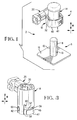
- a connector assembly 2 comprises a connector 4 and a complementary or mating connector 6 for pluggable coupling with the connector 4.
- the connector 6 is in this embodiment a monopole connector in the form of a cylindrical conductive stud 8 extending from a conductive base plate 10 that can be welded or otherwise fixed to a conductive structure, or for connection to a conductor such as a cable for ground or power connection.
- the connector assembly 2 in this embodiment is thus for monopole applications such as ground or power connections in an automobile for example.
- the complementary connector 6 further comprises a locking element 12 in the form of an elastic pin inserted transversely to the coupling direction M in a bore traversing the cylindrical stud 8 proximate the base 10. A pair of ends 13 of the locking element 12 thus project through opposite sides of the mating connector 6 and act as camming and locking elements.
- the receptacle connector 4 comprises a housing or body 14, a locking mechanism 16, a contact section 18, and a connection section 20.
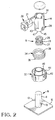
- the body or housing 14 is conductive, and is stamped and formed from sheet metal integrally with the connection section 20 which in this embodiment comprises a crimping barrel 21 for crimping to a cable conductor.
- the body could also be made of an insulative housing receiving a plurality of contacts therein for plugging connection to a plurality of contacts of a complementary connector comprising a housing and a complementary plurality of terminals.
- the contact section 18 mounted within the body 14 can be electrically connected to the body 14. It is also possible to provide a contact section stamped integrally from the body 14 that engages the complementary stud 8.
- the separate contact section 18 however can be made of a material with greater elasticity than the connection section material, and in this embodiment is in the form of an approximately cylindrical part having a plurality of contact arms 23 extending in the mating direction M arranged around the circumference of the contact section and having inwardly bowed contacts (see figure 13) that resiliently bias against the contact surface 25 of the cylindrical stud 8.
- the ring support sections 26, 27 at the top and bottom of the contact section 18 support the contact arms 23 that extend therebetween, and also provide mechanical and electrical connection with the conductive body 14 as best seen in figure 13.
- the connector 4 has a mating section 28 comprising a cavity 30 for receiving the contact section 18 therein, the mating section formed by the housing 14 for pluggable connection to the mating section of the complementary connector 6.
- the locking mechanism 16 is mounted to the housing 14 and forms part of the mating section 28, the locking mechanism comprising a locking element 32 and a spring member 34.
- the locking element 32 is substantially in the form of a ring rotatably movably mounted on the housing 14.
- the spring member 34 has an attachment portion in the form of an end protrusion 36 that attaches to the locking element, and a second attachment portion in the form of a further end protrusion 38 that attaches to the housing 14, such that the locking member 32 is resiliently movable in a transverse direction with respect to the connector housing 14.
- the spring member 34 acts in torsion and produces a torque spring bias between he locking element and the housing.
- a locking member 32 that is movable in a direction transverse T to the mating direction M, and preferably perpendicularly to the mating direction M, in a linear or non circular motion whilst nevertheless providing the secure locking effect according to this invention.
- a rotational movement of the locking element and provision of the torsion spring 34 provides a simple and reliable solution.
- the locking element in this embodiment is moulded from a plastic or similar mouldable material and comprises an inner substantially cylindrical wall 40 that is inserted into the housing cavity 30, and an outer wall 42 spaced from the inner wall 40 with a gap 44, the outer wall 42 positioned outside of an external surface 43 of the housing 14.
- a mating-end wall portion 45 of the housing 14 is thus received in the gap 44 of the locking element.
- a mating face wall 46 interconnects the inner and outer walls 40, 42 proximate a mating end 47 of the connector.
- the mating face wall 46 is provided with entry portions in the form of cutouts 48 adapted to receive the camming studs or projections 13 of the mating connector 6 therethrough into a camming slot 50 formed in the inner wall 40.
- the camming protrusions 13 and camming slot 50 thus form complementary means that interengage to resiliently bias the locking element during coupling in the mating direction, transversely to the mating direction, and at full coupling bias the locking element to the fully locked position thereby securing the connectors in the fully coupled position.
- the camming slot 50 is advantageously provided on the moulded locking element and can thus be easily shaped at low cost, it is nevertheless possible to provide the camming groove on the complementary connector 6 and the camming protrusion on the locking element. This would for example be cost effective where the connector 6 comprises a insulative housing with camming grooves moulded therein.
- the monopole conductor 8 is preferably maintained as simple as possible for cost reasons, and view of exposure of the stud 8 when mounted to a structure or the like, whereby it is more advantageous to keep the stud 8 as simple as possible and provide the complicated functional features on the locking element that is removably pluggable to the structure.
- the camming slot 50 in the locking element comprises an oblique transition portion 52 that may for example have a substantially helical shape, extending from the entry portion 48, the camming slot 50 further comprising a locking portion 54 extending transversely to the mating direction M and preferably orthogonally thereto, the locking portion having an end 55 defining a rest position against which the complementary camming protrusion 13 abuts in the fully coupled position.
- the locking portion 54 may also be provided with a slight recess directed towards the mating end 47 in order to ensure that even under conditions of vibration and application of an uncoupling force on the connector 6, the locking element 32 remains resiliently biased against the complementary locking protrusions.
- the locking element further comprises a transverse guide element 56 that engages with a complementary guide member 57 (see figure 3) of the housing 14 in order to guide the transverse movement T of the locking element with respect to the housing 14, whilst retaining the locking element to the housing 14 in the mating direction M.
- the guide members constitute a guide protrusion 56 protruding from the inner wall 40 of the locking element and received in a slot 57 extending transversely across the body 14 from an assembly entry portion 58 to an end 59.
- the entry portion 58 extends in the mating direction M to a spring attachment extension or cutout 60 in which the inwardly directed attachment portion 38 (see figure 2) of the spring 34 projects, such that the spring attachment portion 38 is retained to the housing 14 in the transverse direction (T).
- the connector housing 14 further comprises a mating direction guide member 62 in the form of a slot extending from the mating end 47 of the housing 14, in the mating direction to an end 63 for receiving complementary guide portions of the mating connector 6 therein.
- the complementary guide portions are in this embodiment advantageously formed by the camming protrusions or locking elements 13, such that the connectors 4, 6 are polarised and guided with respect to each other during coupling whilst the locking element is transversely resiliently biased.
- the guiding and polarising of the connectors may however be performed by other guide means, or by providing complementary non-symmetrical shapes of the connectors such that only specific orientations are permitted with respect to each other. In the present monopole embodiment, it is however advantageous to utilise the locking and camming protrusions 13 also for guiding of the connectors in the mating direction, taking account of the torque or force applied by the spring 34.
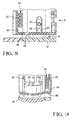
- the camming or locking protrusion 13 is inserted through the locking element entry portion 48 and abuts the oblique angled transitional camming surface of the transitional camming portion 52 and simultaneously enters the connector body guide slot 62.
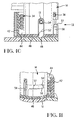
- the locking element is transversely biased n opposition to he spring force of the spring member which is wound to provide spring torsion on the locking element until the fully coupled position is reached and the locking element resiliently rotates from the extreme transitional state shown in figure 8 and figure 9, to the fully coupled locked or rest position shown in figure 10 and figure 11, where the locking protrusion 13 abuts against the rest surface 54 of the camming slot locking portion 54.
- transverse locking surface 53 of the locking portion 54 thus securely retains the connectors in a locked fully coupled position. If coupling is incomplete, the resilient bias of the oblique camming surface 52 against the complementary protrusion 13 will cause the connectors to move to the initial coupling position shown in figures 6 and 12, whereby as best seen in figure 12 the contact section 18 is electrically disconnected from the mating contact section 8. Incorrect coupling is thus detected at an early stage and inadvertent disconnection during operation is avoided.
Landscapes
- Details Of Connecting Devices For Male And Female Coupling (AREA)
Priority Applications (1)
| Application Number | Priority Date | Filing Date | Title |
|---|---|---|---|
| EP19990104344 EP0949721B1 (de) | 1998-03-10 | 1999-03-04 | Einsteckbarer und verriegelbarer einpoliger Steckverbinder |
Applications Claiming Priority (3)
| Application Number | Priority Date | Filing Date | Title |
|---|---|---|---|
| EP98400552 | 1998-03-10 | ||
| EP98400552 | 1998-03-10 | ||
| EP19990104344 EP0949721B1 (de) | 1998-03-10 | 1999-03-04 | Einsteckbarer und verriegelbarer einpoliger Steckverbinder |
Publications (2)
| Publication Number | Publication Date |
|---|---|
| EP0949721A1 true EP0949721A1 (de) | 1999-10-13 |
| EP0949721B1 EP0949721B1 (de) | 2003-06-11 |
Family
ID=26151589
Family Applications (1)
| Application Number | Title | Priority Date | Filing Date |
|---|---|---|---|
| EP19990104344 Expired - Lifetime EP0949721B1 (de) | 1998-03-10 | 1999-03-04 | Einsteckbarer und verriegelbarer einpoliger Steckverbinder |
Country Status (1)
| Country | Link |
|---|---|
| EP (1) | EP0949721B1 (de) |
Cited By (2)
| Publication number | Priority date | Publication date | Assignee | Title |
|---|---|---|---|---|
| EP1600357A1 (de) * | 2004-05-26 | 2005-11-30 | Favess Co., Ltd. | Drehmomentsensor, Kabelbaum, elektrische Servolenkung und Kontakthalterung |
| WO2019072513A1 (de) * | 2017-10-13 | 2019-04-18 | Robert Bosch Gmbh | Hochstromverbindung |
Citations (4)
| Publication number | Priority date | Publication date | Assignee | Title |
|---|---|---|---|---|
| US3681742A (en) * | 1970-07-01 | 1972-08-01 | Tkdi & Sealtron Corp | Electrical connector, sleeve, and method for assembling |
| US4943182A (en) * | 1988-03-14 | 1990-07-24 | Ecia - Equipments Et Composants Pour L'industrie Automobile | Rapid fastener of the bayonet type |
| DE4232951A1 (de) * | 1992-10-01 | 1994-04-07 | Bosch Gmbh Robert | Zündanlage für Brennkraftmaschinen |
| US5464301A (en) * | 1994-06-21 | 1995-11-07 | The United States Of America As Represented By The Administrator Of The National Aeronautics And Space Administration | Rotary latch |
-
1999
- 1999-03-04 EP EP19990104344 patent/EP0949721B1/de not_active Expired - Lifetime
Patent Citations (4)
| Publication number | Priority date | Publication date | Assignee | Title |
|---|---|---|---|---|
| US3681742A (en) * | 1970-07-01 | 1972-08-01 | Tkdi & Sealtron Corp | Electrical connector, sleeve, and method for assembling |
| US4943182A (en) * | 1988-03-14 | 1990-07-24 | Ecia - Equipments Et Composants Pour L'industrie Automobile | Rapid fastener of the bayonet type |
| DE4232951A1 (de) * | 1992-10-01 | 1994-04-07 | Bosch Gmbh Robert | Zündanlage für Brennkraftmaschinen |
| US5464301A (en) * | 1994-06-21 | 1995-11-07 | The United States Of America As Represented By The Administrator Of The National Aeronautics And Space Administration | Rotary latch |
Cited By (6)
| Publication number | Priority date | Publication date | Assignee | Title |
|---|---|---|---|---|
| EP1600357A1 (de) * | 2004-05-26 | 2005-11-30 | Favess Co., Ltd. | Drehmomentsensor, Kabelbaum, elektrische Servolenkung und Kontakthalterung |
| US7308833B2 (en) | 2004-05-26 | 2007-12-18 | Favess Co., Ltd. | Torque sensor, wire harness, electric power steering assembly and terminal holder |
| WO2019072513A1 (de) * | 2017-10-13 | 2019-04-18 | Robert Bosch Gmbh | Hochstromverbindung |
| CN111164837A (zh) * | 2017-10-13 | 2020-05-15 | 罗伯特·博世有限公司 | 大电流连接器 |
| US11121492B2 (en) | 2017-10-13 | 2021-09-14 | Robert Bosch Gmbh | High-current connector |
| CN111164837B (zh) * | 2017-10-13 | 2022-02-18 | 罗伯特·博世有限公司 | 大电流连接器 |
Also Published As
| Publication number | Publication date |
|---|---|
| EP0949721B1 (de) | 2003-06-11 |
Similar Documents
| Publication | Publication Date | Title |
|---|---|---|
| EP0891644B1 (de) | Verriegelungsvorrichtung für einen steckverbinder | |
| EP0232288B1 (de) | Schubsteckverbinder mit langer lebensdauer | |
| KR100839329B1 (ko) | 직각 동축 전기 커넥터, 동축 전기 커넥터 어셈블리 및 직각 동축 커넥터 어셈블리 제조 방법 | |
| US5775931A (en) | Electrical connector latching system | |
| EP0903815B1 (de) | Kabelverbinderanordnung | |
| US5580268A (en) | Lockable electrical connector | |
| CA2308319C (en) | Wire harness connector | |
| US6196856B1 (en) | Floating connector assembly | |
| US7731520B1 (en) | Blade and receptacle power connector | |
| US20100279535A1 (en) | Locking apparatus for electrical connectors | |
| CN113285265A (zh) | 电连接器及电连接器组合 | |
| JPH05275135A (ja) | 雌型電気端子 | |
| US6033250A (en) | Latching connector | |
| US7329158B1 (en) | Push-lock terminal connection assembly | |
| KR100396978B1 (ko) | 래칭 포스트, 래칭 장치 및 전기 커넥터 | |
| EP0949721B1 (de) | Einsteckbarer und verriegelbarer einpoliger Steckverbinder | |
| CA3221752C (en) | Circular modular pluggable connector | |
| EP0911211B1 (de) | Steckverbindungsgruppe für einer abnehmbaren Vorrichtung | |
| CA2346757C (en) | Plug connector | |
| EP0967693B1 (de) | Schwimmende Steckeranordnung | |
| EP3796479B1 (de) | Niederspannungsverbinder | |
| JP2023077186A (ja) | コネクタ | |
| WO1996000455A1 (en) | Connector assembly | |
| HK1018552A (en) | Locking device for a connector |
Legal Events
| Date | Code | Title | Description |
|---|---|---|---|
| PUAI | Public reference made under article 153(3) epc to a published international application that has entered the european phase |
Free format text: ORIGINAL CODE: 0009012 |
|
| AK | Designated contracting states |
Kind code of ref document: A1 Designated state(s): DE FR GB |
|
| AX | Request for extension of the european patent |
Free format text: AL;LT;LV;MK;RO;SI |
|
| 17P | Request for examination filed |
Effective date: 20000228 |
|
| AKX | Designation fees paid |
Free format text: DE FR GB |
|
| 17Q | First examination report despatched |
Effective date: 20010628 |
|
| GRAH | Despatch of communication of intention to grant a patent |
Free format text: ORIGINAL CODE: EPIDOS IGRA |
|
| GRAH | Despatch of communication of intention to grant a patent |
Free format text: ORIGINAL CODE: EPIDOS IGRA |
|
| GRAA | (expected) grant |
Free format text: ORIGINAL CODE: 0009210 |
|
| AK | Designated contracting states |
Designated state(s): DE FR GB |
|
| REG | Reference to a national code |
Ref country code: GB Ref legal event code: FG4D |
|
| RIC1 | Information provided on ipc code assigned before grant |
Ipc: 7H 01R 13/213 B Ipc: 7H 01R 24/00 A |
|
| REF | Corresponds to: |
Ref document number: 69908696 Country of ref document: DE Date of ref document: 20030717 Kind code of ref document: P |
|
| PGFP | Annual fee paid to national office [announced via postgrant information from national office to epo] |
Ref country code: GB Payment date: 20040205 Year of fee payment: 6 |
|
| ET | Fr: translation filed | ||
| PLBE | No opposition filed within time limit |
Free format text: ORIGINAL CODE: 0009261 |
|
| STAA | Information on the status of an ep patent application or granted ep patent |
Free format text: STATUS: NO OPPOSITION FILED WITHIN TIME LIMIT |
|
| 26N | No opposition filed |
Effective date: 20040312 |
|
| PG25 | Lapsed in a contracting state [announced via postgrant information from national office to epo] |
Ref country code: GB Free format text: LAPSE BECAUSE OF NON-PAYMENT OF DUE FEES Effective date: 20050304 |
|
| GBPC | Gb: european patent ceased through non-payment of renewal fee |
Effective date: 20050304 |
|
| REG | Reference to a national code |
Ref country code: FR Ref legal event code: PLFP Year of fee payment: 18 |
|
| REG | Reference to a national code |
Ref country code: FR Ref legal event code: PLFP Year of fee payment: 19 |
|
| REG | Reference to a national code |
Ref country code: FR Ref legal event code: PLFP Year of fee payment: 20 |
|
| PGFP | Annual fee paid to national office [announced via postgrant information from national office to epo] |
Ref country code: DE Payment date: 20180220 Year of fee payment: 20 |
|
| PGFP | Annual fee paid to national office [announced via postgrant information from national office to epo] |
Ref country code: FR Payment date: 20180111 Year of fee payment: 20 |
|
| REG | Reference to a national code |
Ref country code: DE Ref legal event code: R071 Ref document number: 69908696 Country of ref document: DE |