EP0950445A2 - Procédé et dispositif pour la fabrication de ressorts hélicoidaux - Google Patents
Procédé et dispositif pour la fabrication de ressorts hélicoidaux Download PDFInfo
- Publication number
- EP0950445A2 EP0950445A2 EP99104825A EP99104825A EP0950445A2 EP 0950445 A2 EP0950445 A2 EP 0950445A2 EP 99104825 A EP99104825 A EP 99104825A EP 99104825 A EP99104825 A EP 99104825A EP 0950445 A2 EP0950445 A2 EP 0950445A2
- Authority
- EP
- European Patent Office
- Prior art keywords
- wire
- spring
- cutting
- coil
- forming
- Prior art date
- Legal status (The legal status is an assumption and is not a legal conclusion. Google has not performed a legal analysis and makes no representation as to the accuracy of the status listed.)
- Withdrawn
Links
Images

Classifications
-
- B—PERFORMING OPERATIONS; TRANSPORTING
- B21—MECHANICAL METAL-WORKING WITHOUT ESSENTIALLY REMOVING MATERIAL; PUNCHING METAL
- B21F—WORKING OR PROCESSING OF METAL WIRE
- B21F3/00—Coiling wire into particular forms
- B21F3/02—Coiling wire into particular forms helically
Definitions
- the present invention relates to an apparatus for making coil or helical springs.
- the invention further relates to a method for making said coil or helical springs.
- the present invention relates to an apparatus and method for bending metal wires, for example for making spiral coils having a revolution solid configuration the generatrix line of which can comprise any combinations of algebraic lines; the revolution solid also having a comparatively high conicity and a turn variable pitch.
- the first of this operating function is that of feeding the wire metal, which is obtained by opposite rollers which, by pressing on the wire and rotating with the same peripheral turning speed, cause the wire to be driven in an axial direction thereof, while subjecting the wire to a pushing force depending on the stress the wire must be subjected to.
- a second operating function is that of bending the wire, which is obtained by bending tools adapted to offset the wire rectilinear path and to cause the wire to yield according to a set bending radius.
- a third operating function is that of moving the coil spring turns away from one another which is obtained by tools arranged transversely of the spring coil turns and engaged between the turns so as to move away the first turn from its bending plane, thereby providing a set pitch between the adjoining turns.
- a fourth operating function is that of cutting the wire, which is obtained by two cutting tools, of which one is movable with respect to the other in the cutting plane, said tools having a suitable stiffness and being driven on an accurate driving path, said tools being moreover subjected to a comparatively high force for overcoming the breaking limit of the wire.
- the coil spring making machines must also be designed depending on the conditions imposed by the geometry of the spring coil turns as well as by the driving pattern of the turn forming feet, both depending on the technological process thereon the machine is based, and on the dynamic construction of said machine.
- the operating path of the forming foot elements must fit as far as possible the homothety theory of the turns, both considering the variation of the coil spring geometric pattern (for example in the presence of a possible tapering or pitch variation), and in changing a set diameter in order to match the resilient return effects of the wire material (in fact, as the coil spring diameter varies, the amount of the correction to be performed must be correspondingly changed, and this parameter, as is known, being not linearly related to the geometrical parameters).
- a further problem is that the use of a pre-hardened steel material wire, which is at present broadly diffused, would generate cutting problems for cutting the end portions of each individual made spring, as well as very burr formation problems.
- the aim of the present invention is to overcome the above mentioned problems of prior coil spring making machines or apparatus, by providing an improved coil spring making apparatus which can properly operate starting from a simple information related to the data directly contained in the spring configuration or design.
- a main object of the present invention is to provide such a coil spring making apparatus which also allows tapering or conical coil springs to be easily made.
- an apparatus for making coil springs comprising a wire feeding assembly, and being characterized in that it further comprises a supporting assembly for supporting at least a coil spring turn forming foot element, a tool for defining an axial pitch of said coil spring as well as a cutting assembly, said foot element supporting assembly comprising a plurality of slides, driven by respective driving servomotors controlled by a digitally controlled processor, said slides being adapted to be oriented according to directions adapted to provide a proper geometrical pattern of the turns of said coil spring, by arranging said foot elements opposite to the wire feeding direction in order to cause said wire to be yielded and deformed, depending on the technological features of said wire.
- the invention also relates to a method for making coil springs, starting from a wire supplied by the inventive apparatus, characterized in that said method comprises a step of detecting the technological properties of said wire, said detecting step being carried out by providing technological data related to the spring coil wire by using said apparatus, a processing step for processing said data in order to provide a correlation curve representative of the elastic-plastic performance of the wire, and an adjusting step for adjusting the tool assemblies of said apparatus in order to properly make the coil spring.
- the present invention intends to solve the geometrical problems related to the coil spring making processes, while relating said problem to the related kinematic problem to be properly solved in all of the spring making apparatus.
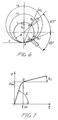
- the first of said theorems specifically relates to the geometrical pattern of the circular turn of a coil spring: in fact, it is known that the winding circumference c of a coil spring turn, made by suitable tools or foot elements, P 1 and P 2 , tangent to said circumference and the first of which is arranged at - ⁇ (for example - 45°) and the second of which is arranged at + ⁇ (+45°) with respect to a straight line passing through the center O (see Figure 6) is characterized by the following features:
- the second theorem relates to the wire deforming technology or method; actually, the deforming wire condition, the wire being considered as an originally rectilinear beam having a constant cross-section, is that overcoming the yield limit or point Q (see Figure 7) and causing the wire to plastically yield by properly calibrating the yielding amount depending on a unit yielding deformation e sn and depending on the elastic-plastic module E 1 .
- the deformation or strain y m must be related to the material type and the processing thereof, to the square of the straining force application arm L and to the reverse of the radius r f of the circular cross-section.
- the wire After straining, the wire will recover its resilient characteristics starting from the size of a circular turn different from that set for the straining: this is conventionally called resilient recovery and constitutes the subject matter of very complex evaluations.
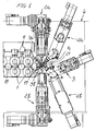
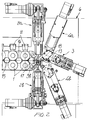
- the coil spring making apparatus comprises a wire roller feeding assembly 1, two cutting units 2a and 2b, and a first-foot element assembly 3, as well as two discrete second-foot element assemblies, i.e. an assembly 4a for a right spring and an assembly 4b for a left spring (see the figure).
- the bed 6 supports, in addition to the mentioned assemblies, also the axial pitch defining or forming devices 5a and 5b.
- the driving or entraining means 1 comprise several pairs of opposite rollers which can be clamped against one another by any known methods (for example by using oleodynamic jacks 11), for clamping against the wire 12; in particular, said rollers are rotatively driven about their rotary axis by one or more electric motors coupled by known driving elements.
- the clamping force, and consequent friction component, associated with the rotary movement of the rollers will be transmitted to the wire thereby causing said wire to be fed toward the forming foot elements 13 and 14; as shown, along the wire path a plurality of wire guiding elements 15, 16 and 17 for properly guiding the wire while preventing it from being deflected under peak loads are provided.
- the first foot element 13 can be interposed on the wire path thereby causing a first bending step by exceeding or overcoming the wire yielding point in the section arranged at the end of the wire guiding element 17.
- the second wire bending step is carried out by affecting the wire path by the second foot element 14: the latter, in particular, will further strain the wire so as to provide the end radius of the spring before the resilient recovery.
- the wire is processed by the axial pitch forming device 5a, specifically designed for straining the coil spring turn in a direction perpendicular to its laying plane.
- the device 5a it would be also possible to use a device 18, the so-called vertical pitch forming device, also adapted to offset the trajectory of the turn being formed, by straining the wire under a twisting force.
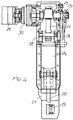
- the cutting unit of Figures 4 and 5 comprises two tools, i.e. the counter-cutting pin 19 and the cutting tool 20, on which the turn 21 is entrained upon formation.
- the spring wire must be properly cut and, to that end, the cutting tool 20 is driven transversely of the wire 21a in order to cut it by the counter-cutting pin 19.
- the spring is a cylindrical type of spring, then the spring turn diameter will be held constant, and the trajectory of the wire to be cut will always pass through the position 21a; on the contrary, as the spring is a conical or tapering type of spring, the diameter of the spring will change and its trajectory could be extended up to the position 21b. In this case, however, the necessary space would interfere against the cutting tool 20a.
- the present invention provides a novel solution of causing the cutting tool to be rearwardly displaced to the position 20b up to the end of the making of the spring. As the spring has been made, the cutting tool will be recovered to the cutting position 20a in order to perform a cutting movement in a cross direction of the wire axis.
- the combination of the two cutting movements is carried out by holding the supporting construction 27 stationary and displacing the slide 24 in two direction, i.e. the cutting vertical direction by the connecting rod 22-crank mechanism 23, the connecting rod 28 foot end of which is vertically guided, while being pivoted to the slide 24; and the swinging direction about the pin 28, as controlled by the rocking element 26 of the cam 25 rigid with the crank shaft 23.
- the cutting is carried out by using an electric motor 29 coupled, through the reduction gear unit 30, to the crankshaft 23: for each full revolution of this shaft, a cutting cycle will be performed corresponding to the following operating steps: feeding of the cutting tool to the position 20a; downward displacement of said cutting tool against the counter-cutting pin 19, and cutting of the wire arranged at 21a; upwardly recovering and withdrawing to the position 20b.
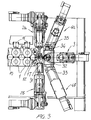
- the apparatus according to the invention can also be used for making torsion or twisting springs (see Figure 3).
- a main feature of the invention is that of providing the above mentioned two movements or displacements by the already positioned units 3 and 4a, of which only the unit 3 must be turned to assume a horizontal orienting (x coordinate), on said unit 3 being mounted a device 33 (which, accordingly, is rigid with the slide of the unit 3) supporting the vertical slide 32 to which the general purpose foot element 31 is coupled.
- the movement according to the vertical coordinate y is transmitted by the unit 4a through the supporting element 34 engaged in the guide 35 rigid with the slide of the unit 4a.
- the dynamic straining of the wire is carried out by pushing said wire against the rollers 1 and using the wire guiding elements 15, 16 and 17, while properly displacing the axis thereof by the foot element 31, while the end cutting operation will be performed by the cutting unit 2a.
- the apparatus of the present invention is specifically designed for timing its operating steps by servomotors directly coupled to each of the driving axes (the operating units), without any mechanical connections between said axes.
- motion laws and mathematical relationships controlling said operating steps would be imposed by proper software algorithms to provide any desired types of spring without any mechanical limitations.
- this novel technical solution would allow to pass from a type of spring to another without performing complex adjustment mechanical operations.
- a servomotor having a double speed range is used: in the first of said ranges, it will operate under a constant torque (this being the low speed range), whereas in the secondof said ranges it will operate with a constant power (this being the high speed range).
- the servomotor (or a plurality of servomotors arranged with a mechanical and electrical parallel relationship) is driven by a digital controlling device, in cooperation with other servomotors forming the other driving axes of the diameter, pitch forming devices as well as of the cutting devices.
- the turn diameter forming axes comprise, as stated, three individual slides each of which is controlled or driven by its servomotor, the slides being fixedly mounted on the machine both as a right coil spring is made and as a left coil spring is made.
- the displacement or driving axes will be perfectly directed according to the theoretically proper directions, as required by the turn geometry theorem.
- the axis of the first foot element is constituted by the same slide which can be oriented to the two positions required by the right and left coil, in addition to a horizontal position in order to provide displacements according to cartesian axes as used for making torsion springs, clamping ring elements or other constructions of springs and related articles.
- the axis of the second foot element is provided with two separated or discrete slides, each arranged in a proper geometrical direction according to the oriented rectilinear trajectories: one at +66.5° in the first quadrant for right coil spring, and another at -66.5° in the fourth quadrant for left coil springs.
- the apparatus according to the invention specifically provides for using a software approach, based on algorithms controlled by the digitally controlling device, which has been specifically designed for controlling all of the displacement axes. This will allow to switch from a right spring to a left spring without requiring complex replacing operations for replacing machine parts with consequent pre-adjustments of the apparatus.
- a withdrawing movement of the cutting tool from the turn winding plane has been specifically designed, thereby preventing the coil wire from interfering against the tool, while eliminating the further drawback of an excessively long displacement of the tool, as in a case of a vertical withdrawing provided to the same end on the most part of prior coil spring making machines.
- the withdrawal of the cutting plane, timed with the upward and downward movement is automatized by a specifically designed mechanism, thereby reducing to a minimum the cutting stroke, and the related working of the system, even in the presence of comparatively high cutting forces, thereby drastically reducing the impact speed between the cutting tools and wire during the cutting operation.
- the system constitutes and axis of the apparatus and is so related to the other drives as to properly combine the cutting operation with a set wire length for completing the spring.
- This system comprises a servomotor and mechanical amplifier mechanisms for amplifying the forces with an optimum ratio of the installed power and the operating efficiency.
- the present invention also comprises a method for obviating a lacking of proper data on the technological characteristics of the wire, by using the same winding apparatus as an instrument for properly detecting said data, by a statistic type of measurement and processing routine, for example according to the following procedure:
- the program will provide a statistic correction of the reading errors, a calculation of the regression curve representing the elastic-plastic properties of the wire, and will supply to the apparatus the precise characteristic of the wire material under examination, as required by the curving process and with a very accurate relationship with the desired result: i.e. the making of a patterned spring without any subjective interventions of the operator and without the need of performing in a technological laboratory expensive measurement operations.
- the pitch routine would provide the operator with a small spring piece with some regions thereof for detecting the made pitches, measuring said pitches and sending their values to the controller.
- the programming unit would be provided, also for the pitch, with real values for properly adjusting the apparatus tools to precisely make the spring.
- the wire material can have different characteristics, the evaluation thereof being performed by an in-machine test thereby allowing the functional performance to be automatically preset.
Landscapes
- Engineering & Computer Science (AREA)
- Mechanical Engineering (AREA)
- Wire Processing (AREA)
- Springs (AREA)
Applications Claiming Priority (2)
| Application Number | Priority Date | Filing Date | Title |
|---|---|---|---|
| ITMI980815 | 1998-04-17 | ||
| IT98MI000815 IT1303020B1 (it) | 1998-04-17 | 1998-04-17 | Apparecchiatura per la fabbricazione di molle avvolte a spirale eprocedimento di produzione relativo |
Publications (2)
| Publication Number | Publication Date |
|---|---|
| EP0950445A2 true EP0950445A2 (fr) | 1999-10-20 |
| EP0950445A3 EP0950445A3 (fr) | 2001-01-17 |
Family
ID=11379810
Family Applications (1)
| Application Number | Title | Priority Date | Filing Date |
|---|---|---|---|
| EP99104825A Withdrawn EP0950445A3 (fr) | 1998-04-17 | 1999-03-11 | Procédé et dispositif pour la fabrication de ressorts hélicoidaux |
Country Status (2)
| Country | Link |
|---|---|
| EP (1) | EP0950445A3 (fr) |
| IT (1) | IT1303020B1 (fr) |
Cited By (3)
| Publication number | Priority date | Publication date | Assignee | Title |
|---|---|---|---|---|
| JP2013226584A (ja) * | 2012-04-26 | 2013-11-07 | Nhk Spring Co Ltd | コイリングマシンの制御装置と、コイルばねの製造方法 |
| JP5403841B1 (ja) * | 2013-04-16 | 2014-01-29 | 新興機械工業株式会社 | ばね製造機 |
| EP3677360A1 (fr) * | 2019-01-07 | 2020-07-08 | Shinko Machinery Co., Ltd. | Machine de fabrication de ressorts |
Family Cites Families (4)
| Publication number | Priority date | Publication date | Assignee | Title |
|---|---|---|---|---|
| JPS5645240A (en) * | 1979-09-19 | 1981-04-24 | Keihin Hatsujo Kk | Torsion spring manufacturing machine |
| JP3172221B2 (ja) * | 1991-11-18 | 2001-06-04 | 株式会社東京コイリングマシン製作所 | コイルばねの製造方法 |
| DE9213164U1 (de) * | 1992-09-30 | 1993-01-14 | WAFIOS Maschinenfabrik GmbH & Co KG, 7410 Reutlingen | Windeeinrichtung für Drahtform-Vorrichtungen, insbesondere Federwindemaschinen |
| DE19611661C2 (de) * | 1996-03-25 | 1998-09-10 | Wafios Maschinen Wagner | Vorrichtung zum Formen von Draht, insbesondere Universal-Federwindemaschine |
-
1998
- 1998-04-17 IT IT98MI000815 patent/IT1303020B1/it active IP Right Grant
-
1999
- 1999-03-11 EP EP99104825A patent/EP0950445A3/fr not_active Withdrawn
Cited By (3)
| Publication number | Priority date | Publication date | Assignee | Title |
|---|---|---|---|---|
| JP2013226584A (ja) * | 2012-04-26 | 2013-11-07 | Nhk Spring Co Ltd | コイリングマシンの制御装置と、コイルばねの製造方法 |
| JP5403841B1 (ja) * | 2013-04-16 | 2014-01-29 | 新興機械工業株式会社 | ばね製造機 |
| EP3677360A1 (fr) * | 2019-01-07 | 2020-07-08 | Shinko Machinery Co., Ltd. | Machine de fabrication de ressorts |
Also Published As
| Publication number | Publication date |
|---|---|
| IT1303020B1 (it) | 2000-10-20 |
| ITMI980815A1 (it) | 1999-10-17 |
| EP0950445A3 (fr) | 2001-01-17 |
Similar Documents
| Publication | Publication Date | Title |
|---|---|---|
| EP3238850B1 (fr) | Machine de pliage de fil | |
| US8393191B2 (en) | Wire forming apparatus | |
| US4154073A (en) | Automatic straightening machine | |
| JPH01162520A (ja) | 物品の曲げ加工方法およびその装置 | |
| US4947670A (en) | Universal automatic spring-making machine | |
| US5452598A (en) | Automatic spring formation apparatus | |
| EP0198984B1 (fr) | Dispositif de cintrage | |
| EP3254782B1 (fr) | Procédé et appareil d'étalonnage automatique d'une machine de pliage de fil | |
| US5203191A (en) | Versatile automatic metal strip working machine | |
| EP2332666B1 (fr) | Dispositif de formation de cylindre et procédé de formation de cylindre | |
| KR100908981B1 (ko) | 밴딩 기능이 부착된 파이프 성형기 | |
| US6701765B2 (en) | Spring manufacturing apparatus | |
| US5105641A (en) | Apparatus for forming wire | |
| US3296851A (en) | Wire-bending machine | |
| EP0950445A2 (fr) | Procédé et dispositif pour la fabrication de ressorts hélicoidaux | |
| US6397900B1 (en) | Apparatus for shaping wire into wire products | |
| EP0408560B1 (fr) | Procédé et dispositif pour faire correspondre automatiquement au moins deux surfaces essentiellement cylindriques qui entrent en contact, en particulier pour l'estampage mechanique | |
| CN110899576B (zh) | 一种螺杆钢丝绳旋转切割装置 | |
| JP3573395B2 (ja) | ヘミング装置及びヘミング方法 | |
| US6283352B1 (en) | Apparatus for a stepwise feeding of a strip-like workpiece | |
| JPS62248527A (ja) | 曲げ加工装置 | |
| JPH0970713A (ja) | H形鋼用切断機 | |
| JPH0790276B2 (ja) | 曲げ加工方法 | |
| EP0804978A1 (fr) | Machine d'enroulement de ressorts hélicoidaux à enroulement simple ou double | |
| EP1980338A2 (fr) | Plieuse |
Legal Events
| Date | Code | Title | Description |
|---|---|---|---|
| PUAI | Public reference made under article 153(3) epc to a published international application that has entered the european phase |
Free format text: ORIGINAL CODE: 0009012 |
|
| AK | Designated contracting states |
Kind code of ref document: A2 Designated state(s): DE ES FR GB |
|
| AX | Request for extension of the european patent |
Free format text: AL;LT;LV;MK;RO;SI |
|
| PUAL | Search report despatched |
Free format text: ORIGINAL CODE: 0009013 |
|
| AK | Designated contracting states |
Kind code of ref document: A3 Designated state(s): AT BE CH CY DE DK ES FI FR GB GR IE IT LI LU MC NL PT SE |
|
| AX | Request for extension of the european patent |
Free format text: AL;LT;LV;MK;RO;SI |
|
| AKX | Designation fees paid |
Free format text: DE ES FR GB |
|
| STAA | Information on the status of an ep patent application or granted ep patent |
Free format text: STATUS: THE APPLICATION IS DEEMED TO BE WITHDRAWN |
|
| 18D | Application deemed to be withdrawn |
Effective date: 20010718 |