EP0950911B1 - Système optique de formation d'images avec un élément optique de diffraction - Google Patents
Système optique de formation d'images avec un élément optique de diffraction Download PDFInfo
- Publication number
- EP0950911B1 EP0950911B1 EP99107181A EP99107181A EP0950911B1 EP 0950911 B1 EP0950911 B1 EP 0950911B1 EP 99107181 A EP99107181 A EP 99107181A EP 99107181 A EP99107181 A EP 99107181A EP 0950911 B1 EP0950911 B1 EP 0950911B1
- Authority
- EP
- European Patent Office
- Prior art keywords
- lens
- optical system
- refractive power
- positive
- lens unit
- Prior art date
- Legal status (The legal status is an assumption and is not a legal conclusion. Google has not performed a legal analysis and makes no representation as to the accuracy of the status listed.)
- Expired - Lifetime
Links
- 230000003287 optical effect Effects 0.000 title claims description 110
- 230000004075 alteration Effects 0.000 claims description 84
- 239000000463 material Substances 0.000 claims description 16
- 238000001228 spectrum Methods 0.000 claims description 15
- 238000001429 visible spectrum Methods 0.000 claims description 7
- 230000005499 meniscus Effects 0.000 claims description 4
- 239000006185 dispersion Substances 0.000 description 10
- 239000011521 glass Substances 0.000 description 8
- 230000007423 decrease Effects 0.000 description 5
- 210000001747 pupil Anatomy 0.000 description 5
- WUKWITHWXAAZEY-UHFFFAOYSA-L calcium difluoride Chemical compound [F-].[F-].[Ca+2] WUKWITHWXAAZEY-UHFFFAOYSA-L 0.000 description 4
- 230000001419 dependent effect Effects 0.000 description 4
- 239000010436 fluorite Substances 0.000 description 4
- 239000011347 resin Substances 0.000 description 4
- 229920005989 resin Polymers 0.000 description 4
- 239000000758 substrate Substances 0.000 description 4
- 230000005484 gravity Effects 0.000 description 3
- 238000012886 linear function Methods 0.000 description 3
- 238000004519 manufacturing process Methods 0.000 description 3
- 230000008901 benefit Effects 0.000 description 2
- 238000010586 diagram Methods 0.000 description 2
- 238000009826 distribution Methods 0.000 description 2
- 230000003595 spectral effect Effects 0.000 description 2
- 206010010071 Coma Diseases 0.000 description 1
- AFCARXCZXQIEQB-UHFFFAOYSA-N N-[3-oxo-3-(2,4,6,7-tetrahydrotriazolo[4,5-c]pyridin-5-yl)propyl]-2-[[3-(trifluoromethoxy)phenyl]methylamino]pyrimidine-5-carboxamide Chemical compound O=C(CCNC(=O)C=1C=NC(=NC=1)NCC1=CC(=CC=C1)OC(F)(F)F)N1CC2=C(CC1)NN=N2 AFCARXCZXQIEQB-UHFFFAOYSA-N 0.000 description 1
- 201000009310 astigmatism Diseases 0.000 description 1
- 239000003086 colorant Substances 0.000 description 1
- 239000000470 constituent Substances 0.000 description 1
- 239000000428 dust Substances 0.000 description 1
- 230000000694 effects Effects 0.000 description 1
- 239000005357 flat glass Substances 0.000 description 1
- 238000003384 imaging method Methods 0.000 description 1
- 238000000034 method Methods 0.000 description 1
- 239000005304 optical glass Substances 0.000 description 1
- 239000004033 plastic Substances 0.000 description 1
- 229920003023 plastic Polymers 0.000 description 1
- 230000009467 reduction Effects 0.000 description 1
- 238000004904 shortening Methods 0.000 description 1
- 230000004304 visual acuity Effects 0.000 description 1
Images










Classifications
-
- G—PHYSICS
- G02—OPTICS
- G02B—OPTICAL ELEMENTS, SYSTEMS OR APPARATUS
- G02B27/00—Optical systems or apparatus not provided for by any of the groups G02B1/00 - G02B26/00, G02B30/00
- G02B27/42—Diffraction optics, i.e. systems including a diffractive element being designed for providing a diffractive effect
- G02B27/4205—Diffraction optics, i.e. systems including a diffractive element being designed for providing a diffractive effect having a diffractive optical element [DOE] contributing to image formation, e.g. whereby modulation transfer function MTF or optical aberrations are relevant
- G02B27/4211—Diffraction optics, i.e. systems including a diffractive element being designed for providing a diffractive effect having a diffractive optical element [DOE] contributing to image formation, e.g. whereby modulation transfer function MTF or optical aberrations are relevant correcting chromatic aberrations
-
- G—PHYSICS
- G02—OPTICS
- G02B—OPTICAL ELEMENTS, SYSTEMS OR APPARATUS
- G02B27/00—Optical systems or apparatus not provided for by any of the groups G02B1/00 - G02B26/00, G02B30/00
- G02B27/0025—Optical systems or apparatus not provided for by any of the groups G02B1/00 - G02B26/00, G02B30/00 for optical correction, e.g. distorsion, aberration
- G02B27/0037—Optical systems or apparatus not provided for by any of the groups G02B1/00 - G02B26/00, G02B30/00 for optical correction, e.g. distorsion, aberration with diffracting elements
-
- G—PHYSICS
- G02—OPTICS
- G02B—OPTICAL ELEMENTS, SYSTEMS OR APPARATUS
- G02B27/00—Optical systems or apparatus not provided for by any of the groups G02B1/00 - G02B26/00, G02B30/00
- G02B27/42—Diffraction optics, i.e. systems including a diffractive element being designed for providing a diffractive effect
- G02B27/4272—Diffraction optics, i.e. systems including a diffractive element being designed for providing a diffractive effect having plural diffractive elements positioned sequentially along the optical path
-
- G—PHYSICS
- G02—OPTICS
- G02B—OPTICAL ELEMENTS, SYSTEMS OR APPARATUS
- G02B27/00—Optical systems or apparatus not provided for by any of the groups G02B1/00 - G02B26/00, G02B30/00
- G02B27/42—Diffraction optics, i.e. systems including a diffractive element being designed for providing a diffractive effect
- G02B27/4288—Diffraction optics, i.e. systems including a diffractive element being designed for providing a diffractive effect having uniform diffraction efficiency over a large spectral bandwidth
Definitions
- the present invention relates to an image forming optical system having a diffractive optical element and, more particularly, to a photographic optical system of telephoto type having a large relative aperture with a refractive optical element and a diffractive optical element used in combination to improve the imaging performance, suited to silver-halide photographic cameras, video cameras, electronic still cameras, etc.
- the optical glasses of extraordinary partial dispersion such as fluorite are advantageous for correcting chromatic aberrations, but have a disadvantage that they are very expensive. In specific gravity, too, they are relatively greater than the other low-dispersion glasses whose partial dispersions are not extra-ordinal. Therefore, the use of fluorite leads also to a drawback that the whole lens system becomes heavier.
- fluorite is 3.18 and FK01 is 3.63 in specific gravity.
- FK5 that has a small extraordinary partial dispersion is 2.46 and BK7 is 2.52 in specific gravity.
- the extraordinary partial dispersion glass surface is relatively susceptible to scratches. Further, FK01 or the like when made in the form of large relative aperture lenses gives rise to another drawback that these lenses are liable to crack when the ambient temperature changes rapidly.
- the telephoto lens disclosed in the above Japanese Laid-Open Patent Application No. Hei 6-324262 is composed of at least one diffractive optical element having a positive refractive power, at least one refractive optical element having a positive refractive power and at least one refractive optical element having a negative refractive power, has an F-number of F2.8 or thereabout and is corrected relatively well for chromatic aberration.
- the telephoto lens disclosed in the above Japanese Laid-Open Patent Application No. Hei 6-331887 is composed of a combination of a diffractive optical element and refractive optical elements, has an F-number of F2.8 or thereabout and is corrected relatively well for chromatic aberration.
- focusing is effected by moving along an optical axis a lens unit disposed in a relatively rear portion, which is light in weight and has a little load on the lens barrel.
- a lens unit which is relatively light in weight and has a relatively little variation of monochromatic aberration during focusing a lens unit which is disposed slightly in the rear (image side) of the middle point of the optical system and which consists of a cemented lens composed of a positive lens and a negative lens and having a negative refractive power as a whole.
- a telephoto lens is not necessarily sufficient for the distribution of refractive power between the diffraction surface (diffractive optical element) and the refractive optical element and for setting of glass materials. Therefore, if the above negative lens unit is used for focusing, the variation of chromatic aberration becomes large.
- US 5,490,014 discloses an inner-focus telephoto lens with reduced chromatic aberrations.
- An object of the invention is to provide an image forming optical system, such as a telephoto lens, which is capable of making chromatic aberrations small enough.
- Another object of the invention is to provide an image forming optical system, such as a telephoto lens, whose chromatic aberrations vary to small extent with focusing.
- an image forming optical system as defined in claim 1.
- an optical system having a diffractive optical element according to the invention is illustrated as a thin system with the paraxial refractive power arrangement shown to explain optical actions in the normal state.
- the optical system takes the form of a telephoto lens, comprising a refractive optical system part M and a diffractive optical element having a diffraction grating formed in a surface D thereof.
- P represents a paraxial on-axial ray of light
- Q represents a pupil paraxial ray of light.
- the diffraction surface D is assumed to be disposed on the object side of the refractive optical system part M, and the refractive optical system part M is considered as a thin single lens.
- Figs. 2A, 2B and 2C are graphs for explaining the correction of chromatic aberrations in the invention.
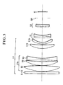
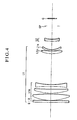
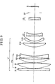
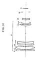
- Figs. 3 to 11 in block diagram show numerical examples 1 to 9 of the invention, respectively.
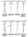
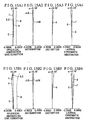
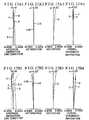
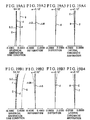
- Figs. 12A1 to 12A4 and 12B1 to 12B4 through Figs. 20A1 to 20A4 and 20B1 to 20B4 graphically show the aberrations of the numerical examples 1 to 9 of the invention, respectively.
- the ones whose figure numbers contain letter "A" are obtained during focusing on an infinitely distant object and the others whose figure numbers contain letter "B" are obtained during focusing on an object at a finite distance.
- D•O denotes a diffractive optical element having a positive refractive power composed of a diffraction grating of revolution symmetry with respect to an optical axis of the optical system.
- L1 denotes a first lens unit having a positive refractive power.
- L2 denotes a second lens unit having a negative refractive power, which is made to axially move toward the image side during focusing from an infinitely distant object to an object at the minimum distance.
- L3 denotes a third lens unit having a positive refractive power.
- SP stands for a stop
- G stands for a glass block such as optical filter or face plate.
- the first lens unit L1 is composed of the diffractive optical element D•O, a first lens subunit L1a of positive refractive power, a positive lens L1p, and a negative lens L1n of meniscus form concave toward the image side.
- the first lens unit L1 is composed of the diffractive optical element D•O, a first lens subunit L1a of positive refractive power and a negative lens L1n of meniscus form concave toward the image side.
- the first lens subunit L1a has a bi-convex positive lens G1, a positive lens G2 and a bi-concave negative lens G3.
- the second lens unit L2 is constructed with a cemented lens composed of a positive lens and a negative lens.
- a third lens unit L3 which is constructed with a cemented lens composed of a positive lens and a negative lens.
- L h D 2 ⁇ D / ⁇ D + h M 2 ⁇ M / ⁇ M
- T h D h ⁇ D ⁇ D / ⁇ D + h M h ⁇ M ⁇ M / ⁇ M
- ⁇ D a refractive power for the diffracted light in the design diffraction order of the diffraction surface D
- ⁇ M a refractive power of the refractive optical system M
- ⁇ D a reduced Abbe number (equivalent to -3.45) of the diffraction surface D
- ⁇ M an Abbe number of the refractive optical system part M (the thin single lens)
- h D a height of incidence of the paraxial on-axial ray on the diffraction surface D
- equations (6) and (7) have their second terms concerned with the refractive optical system part M, because its overall refractive power is substantially positive, the second terms of the equations (6) and (7) take, in most cases, values of the same sign as that of the single lens model. Therefore, discussion may be made by the equations (4) and (5) for the single lens model without causing any particular inconvenience. So, in the following, explanation is made by using the equations (4) and (5).
- the second term is for the longitudinal chromatic aberration coefficient of the refractive optical system part M.
- the first term for the longitudinal chromatic aberration coefficient of the diffraction surface D must take a negative value. That is, the following relation is obtained: h D 2 ⁇ D / ⁇ D ⁇ 0
- the refractive power of the diffraction surface D should be as follows: ⁇ D > 0
- the first term for the lateral chromatic aberration coefficient of the diffraction surface D is found from h D > 0 , h ⁇ D > 0 and ⁇ D ⁇ 0 , to be h D h ⁇ D ⁇ D / ⁇ D ⁇ 0.
- the second term for the lateral chromatic aberration coefficient of the refractive optical system part M is found from h M > 0 , h ⁇ M > 0 , ⁇ M > 0 and ⁇ M > 0 , to be h M h ⁇ M ⁇ M / ⁇ M > 0.
- the lateral chromatic aberration coefficient of the refractive optical system part M is canceled by the lateral chromatic aberration coefficient of the diffraction surface D, thus making it possible to reduce the lateral chromatic aberration coefficient of the entire optical system to a minimum.
- the refractive optical system part M has its longitudinal and lateral chromatic aberration coefficients canceled in each at once, so that it becomes possible to improve the achromatism of the entire optical system.
- the first lens unit of positive refractive power makes a large contribution to chromatic aberration.
- the spectrum curve is usually of the shape shown in Fig. 2A, whose curvature is convex downward and which crosses the abscissa at a design wavelength and another one wavelength, or is achromatized in two colors. That is, it becomes the so-called "achromatic type" spectrum curve.
- the refractive power of the diffraction surface D can be made positive. As is apparent from the equation (9), it is in a wavelength region of " ⁇ > ⁇ 0 " that, as the wavelength increases, the positive refractive power of the diffraction surface D increases as a linear function of variation of the wavelength. Conversely, in the other wavelength region of " ⁇ ⁇ ⁇ 0 ", as the wavelength decreases, the positive refractive power of the diffraction surface D decreases as the linear function of variation of the wavelength.
- the first lens unit L1 of the refractive optical system part M be provided with the first lens subunit L1a consisting of at least one positive lens and at least one negative lens and having a positive refractive power as a whole, and that the conditions (1), (2) and (3) described before be satisfied.
- the spectrum curve of the refractive optical system part M can be controlled with the design wavelength at the center so that the longer wavelength region than the design wavelength is made more under-corrected and the shorter wavelength region is made more over-corrected.
- the position of the minimum point of the spectrum curve can be made to shift to shorter wavelengths.
- the spectrum curve of the refractive optical system part M becomes almost linear in shape over the entire visible spectrum (see Fig. 2C).
- the condition (1) described before is taken into account in determining the refractive power of the diffraction surface D. Achromatization for the entire visible spectrum, including good stability of chromatic correction with focusing, can thus be achieved.
- condition (1) are concerned with the ratio of the refractive powers of the diffraction surface D and the first lens subunit L1a
- the upper limit of the condition (1) is exceeded, as this means that the refractive power of the diffraction surface D is too strong, the longitudinal chromatic aberration spectrum line of the diffraction surface D becomes a large absolute value of the slope.
- the spectrum curve of the refractive optical system part M too, has to decline largely, while keeping the linear shape.
- the pitch of the diffraction grating becomes too much fine to manufacture economically. So, the violation is objectionable.
- the refractive power of the diffraction surface D is weaker than the lower limit of the condition (1), as this implies that the absolute value of the slope of the longitudinal spectrum line of the diffraction surface D is too small, the spectrum curve of the refractive optical system part M cannot be made small in the slope while keeping the linear shape. In the shorter wavelength region than the design wavelength, therefore, a tough curvature convex downward is produced, making it impossible for the diffraction surface D to cancel the longitudinal chromatic aberration. So, the violation is objectionable.
- the inequalities of conditions (2) and (3) have such an aim that, while keeping the refractive optical system part M good in other aberrations than chromatic aberration, the spectrum curve, especially in respect to the longitudinal chromatic aberration, is given a proper slope and its curvature is made looser to sustain the almost linear shape.
- the upper limit of the condition (2) or the lower limit of the condition (3) is exceeded, as this implies that the spectrum curve in the shorter wavelength region than the design wavelength is too much tough in curvature, it becomes difficult for the diffraction surface D to fully correct chromatic aberration.
- the conditions (1), (2) and (3) have their numerical ranges for the values ⁇ D / ⁇ 1a , ⁇ lap and ⁇ 1an respectively more restricted as follows: 0.009 ⁇ ⁇ D / ⁇ 1 a ⁇ 0.021 56 ⁇ ⁇ 1 a p ⁇ 71 30 ⁇ ⁇ 1 a n ⁇ 50
- the conditions (14), (15) and (16) are valid after the conditions (1), (2) and (3) or the condition (13) is satisfied and have an aim to further improve the chromatic aberration and the other various aberrations their variations with focusing and another aim to make the optical system adaptable to the camera having the auto-focus capability by reducing the weight and shortening the forward movement of the focusing lens unit.
- condition (14) give a proper range for the ratio of the refractive powers of the second lens unit and the entire optical system.
- the upper limit of the condition (14) is exceeded, as this means that the refractive power of the second lens unit is too strong, an increase of the refractive power of the first lens unit, too, results.
- the diameter and the focusing movement of the second lens unit decrease, the aberration in the reference setting and the variation of aberrations with focusing both are caused to worsen objectionably.
- the refractive power of the second lens unit weakens beyond the lower limit of the condition (14), an advantage is produced on correction of the aberrations, but the diameter and the focusing movement of the second lens unit increases objectionably.
- the conditions (15) and (16) are set forth for the purpose of correcting the variation of chromatic aberration well. Either when the upper limit is exceeded or when the lower limit is exceeded, the range of variation of chromatic aberration increases greatly. So, these factors are better made to fall within the numerical ranges specified.
- the conditions (14), (15) and (16) have their numerical ranges for the values ⁇ 2 / ⁇ , ⁇ 2p and ⁇ 2n respectively more restricted as follows: ⁇ 2.8 ⁇ ⁇ 2 / ⁇ ⁇ ⁇ 1.7 22 ⁇ ⁇ 2 p ⁇ 25 33 ⁇ ⁇ 2 n ⁇ 47
- the first lens subunit L1a With, in order from the object side to the image side, a positive lens, a positive lens and a negative lens, totaling three lenses, thereby producing an advantage of correcting well spherical aberration, coma and astigmatism and their variations with focusing.
- a negative lens of meniscus form concave toward the image side may be added on the image side of the first lens subunit L1a, thereby much more improving the variation of mainly spherical aberration with focusing.
- ri is the radius of curvature of the i-th lens surface, when counted from the object side
- di is the axial distance between the i-th and (i+1)st surfaces in the reference setting, when counted from the object side
- ni and vi are respectively the refractive index and Abbe number for the spectral d-line of the i-th lens element, when counted from the object side.
- f stands for the focal length
- Fno stands for F-number
- 2 ⁇ stands the field angle.
- the diffraction surface of positive refractive power is the first one, but an additional diffraction surface may be used to thereby obtain a better optical performance.
- the diffraction surface to add may be either positive or negative in refractive power.
- it is better placed near to the image plane of the optical system at a position where the pupil paraxial ray is incident relatively high, and the paraxial on-axial ray is incident relatively low. By this arrangement, lateral chromatic aberration is even better corrected.
- every diffraction surface is applied to a parallel flat plate of glass (except to the filter which, although being a parallel flat glass plate, has no diffraction surface applied), as a base on one side thereof.
- the spherical lens or the aspherical lens may be used as the base for the diffraction surface, and both surfaces of the base may be formed as diffraction surfaces.
- the diffraction surface may be applied to a cementing surface of a cemented lens.
- the material of the base may be anything but glass in particular, provided it is transparent for light.
- the diffraction grating 101 of the diffractive optical element is of kinoform as shown in Fig. 21.
- Fig. 22 shows the wavelength-dependent characteristics of the diffraction efficiency in the first order of the diffractive optical element shown in Fig. 21.
- An actual example of the diffraction grating is constructed on a surface of a substrate 102 with a layer of ultra-violet ray setting resin applied thereon.
- a diffraction grating 103 is thus formed to such a thickness "d" that the diffraction efficiency in the first order becomes 100% at a wavelength of 530 ⁇ m.
- the diffraction efficiency in the design order decreases as the wavelength goes away from the optimized one, or 530 ⁇ m. Meanwhile, in the neighborhood of the design order, that is, in the zero and second orders, the amount of diffracted rays increases. Such an increase of the diffracted rays in the other orders than the design order causes production of flare and leads to lower the resolving power of the optical system.
- Fig. 23 there is shown the MTF (Modulation Transfer Function) characteristic with respect to the spatial frequency when the actual example described above is made up in the grating shape shown in Fig. 21. In this graph, it is understandable that the MTF characteristic drops from the desired value in the low frequency region.
- MTF Modulation Transfer Function
- a laminated type of diffraction grating is shown in Fig. 24 as usable in the diffractive optical element embodying one form of the invention.
- Fig. 25 is the wavelength-dependent characteristics of the diffraction efficiency in the first order of the diffractive optical element in this form.
- the diffraction efficiency in the design order can be increased to higher than 95% over the entire range of useful wavelengths.
- the MTF characteristics with respect to the spatial frequency in this case is shown in Fig. 26.
- the use of the diffractive grating of the laminated type improves the MTF characteristics in the low frequency region. The desired MTF characteristics are thus obtained. It will be appreciated from the foregoing that, if, as the diffractive optical element, the laminated structure is used, further improvements of the optical performance can be achieved.
- the materials are not limited to the ultraviolet setting resin. Other materials such as plastics also may be used instead.
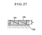
- the first diffraction grating 104 may be formed directly on the substrate. Furthermore, there is no need to make the thicknesses of the two gratings different from each other. In some combinations of materials, the thicknesses of the two gratings may be made equal to each other as shown in Fig. 27. Since, in this case, no grooves are exposed to the outside from the surface of the diffractive optical element, the dust proof is excellent, contributing to an increase of the productivity on the assembling line in manufacturing the diffractive optical elements. Accordingly, more inexpensive optical systems can be produced.
Landscapes
- Physics & Mathematics (AREA)
- General Physics & Mathematics (AREA)
- Optics & Photonics (AREA)
- Spectroscopy & Molecular Physics (AREA)
- Lenses (AREA)
Claims (4)
- Système optique de formation d'image comportant, dans l'ordre d'un côté objet à un côté image, un premier groupe (L1) de lentilles ayant une puissance de réfraction positive et un second groupe (L2) de lentilles ayant une puissance de réfraction négative, ledit second groupe de lentilles étant mobile le long d'un axe optique du système optique pour une mise au point, dans lequel ledit premier groupe de lentilles comporte un premier sous-groupe (L1a) de lentilles d'une puissance de réfraction positive, ledit premier sous-groupe (L1a) de lentilles comportant au moins une lentille positive (G1, G2) et au moins une lentille négative (G3), et dans lequel ledit second groupe (L2) de lentilles comporte une lentille positive et une lentille négative, les surfaces de lentilles réfringentes formant une partie (M) d'un système optique réfringent,
ledit système optique satisfaisant aux conditions suivantes :


où
φ est la puissance de réfraction de l'ensemble dudit système optique,
φ2 est la puissance de réfraction dudit second groupe (L2) de lentilles,
υ2p est le nombre d'Abbe de la matière de ladite lentille positive incluse dans ledit second groupe (L2) de lentilles, et
υlan est le nombre d'Abbe de la matière de la lentille négative (G3), ou une valeur moyenne des nombres d'Abbe des matières des lentilles négatives, incluses dans ledit premier sous-groupe (L1a) de lentilles,
caractérisé
en ce que ledit premier groupe (L1) de lentilles a une surface de diffraction (D) d'une puissance de réfraction positive, et
en ce que ledit système optique satisfait en outre aux conditions suivantes :


où
φD est la puissance de réfraction de ladite surface de diffraction (D) de la puissance de réfraction positive dans ledit premier groupe (L1) de lentilles,
φ1a est la puissance de réfraction dudit premier sous-groupe (L1a) de lentilles,
υ1ap est le nombre d'Abbe de la matière de la lentille positive, ou une valeur moyenne des nombres d'Abbe des matières des lentilles positives (G1, G2), incluses dans ledit premier sous-groupe (L1a) de lentilles, et
υ2n est le nombre d'Abbe de la matière de ladite lentille négative incluse dans ledit second groupe (L2) de lentilles,
et dans lequel la partie réfringente (M) du système optique est construite de façon à produire dans le spectre visible une aberration chromatique longitudinale qui se décale linéairement dans la pente inversement à la raie spectrale de l'aberration chromatique longitudinale linéaire de la surface de diffraction (D). - Système optique selon la revendication 1, satisfaisant en outre à la condition suivante :

- Système optique selon la revendication 1 ou 2, dans lequel ledit premier sous-groupe (L1a) de lentilles comprend, dans l'ordre du côté objet au côté image une première lentille positive (61), une seconde lentille positive (G2) et une lentille négative (G3).
- Système optique selon la revendication 3, dans lequel ledit premier groupe (L1) de lentilles comporte une lentille négative (L1n) sous la forme d'un ménisque concave vers le côté image et disposée sur le côté image dudit premier sous-groupe (L1a) de lentilles.
Applications Claiming Priority (2)
| Application Number | Priority Date | Filing Date | Title |
|---|---|---|---|
| JP12005098 | 1998-04-14 | ||
| JP12005098A JP3342400B2 (ja) | 1998-04-14 | 1998-04-14 | 回折光学素子を有した光学系 |
Publications (3)
| Publication Number | Publication Date |
|---|---|
| EP0950911A2 EP0950911A2 (fr) | 1999-10-20 |
| EP0950911A3 EP0950911A3 (fr) | 2003-10-29 |
| EP0950911B1 true EP0950911B1 (fr) | 2006-06-21 |
Family
ID=14776660
Family Applications (1)
| Application Number | Title | Priority Date | Filing Date |
|---|---|---|---|
| EP99107181A Expired - Lifetime EP0950911B1 (fr) | 1998-04-14 | 1999-04-13 | Système optique de formation d'images avec un élément optique de diffraction |
Country Status (4)
| Country | Link |
|---|---|
| US (1) | US6268969B1 (fr) |
| EP (1) | EP0950911B1 (fr) |
| JP (1) | JP3342400B2 (fr) |
| DE (1) | DE69931992T2 (fr) |
Families Citing this family (16)
| Publication number | Priority date | Publication date | Assignee | Title |
|---|---|---|---|---|
| JP3505099B2 (ja) * | 1999-02-04 | 2004-03-08 | ペンタックス株式会社 | 中望遠レンズ |
| JP3950571B2 (ja) * | 1999-03-10 | 2007-08-01 | キヤノン株式会社 | 撮影光学系 |
| JP4324644B2 (ja) * | 1999-09-29 | 2009-09-02 | 株式会社オーク製作所 | 多波長レーザー光学系 |
| JP3376351B2 (ja) * | 1999-11-29 | 2003-02-10 | キヤノン株式会社 | 光学系及び原稿読取装置 |
| JP2001318309A (ja) * | 2000-05-12 | 2001-11-16 | Canon Inc | 撮影レンズ及びそれを用いた光学機器 |
| JP4652539B2 (ja) * | 2000-08-31 | 2011-03-16 | キヤノン株式会社 | 撮影光学系及びそれを用いた光学機器 |
| JP4641339B2 (ja) * | 2000-09-01 | 2011-03-02 | キヤノン株式会社 | 光学系及びそれを用いた光学機器 |
| JP2005107298A (ja) * | 2003-09-30 | 2005-04-21 | Nikon Corp | 回折光学素子及び回折光学素子の製造方法 |
| JP2005181392A (ja) | 2003-12-16 | 2005-07-07 | Canon Inc | 光学系 |
| JP2006317605A (ja) * | 2005-05-11 | 2006-11-24 | Canon Inc | 撮影光学系及びそれを有する撮像装置 |
| JP4829590B2 (ja) * | 2005-10-25 | 2011-12-07 | キヤノン株式会社 | 撮影光学系及びそれを有する撮像装置 |
| JP2009086566A (ja) * | 2007-10-03 | 2009-04-23 | Olympus Corp | 撮像光学系 |
| DE202008017861U1 (de) | 2008-03-11 | 2010-09-23 | Carl Zeiss Sports Optics Gmbh | Optisches System |
| TWI507726B (zh) * | 2013-02-04 | 2015-11-11 | Largan Precision Co Ltd | 移動對焦光學鏡頭組 |
| JP6387630B2 (ja) * | 2014-03-12 | 2018-09-12 | 株式会社ニコン | 光学系および光学機器 |
| CN109254388B (zh) * | 2018-11-21 | 2023-09-19 | 福建福光股份有限公司 | 远心光学检像系统及成像方法 |
Family Cites Families (22)
| Publication number | Priority date | Publication date | Assignee | Title |
|---|---|---|---|---|
| JPS56165110A (en) * | 1980-05-23 | 1981-12-18 | Canon Inc | Telephoto lens |
| JPS5917519A (ja) * | 1982-07-21 | 1984-01-28 | Canon Inc | 大口径の望遠レンズ |
| US4852984A (en) | 1987-02-25 | 1989-08-01 | Canon Kabushiki Kaisha | Telephoto lens of large aperture ratio |
| JPH07101253B2 (ja) | 1987-04-03 | 1995-11-01 | キヤノン株式会社 | フロ−テイングを利用した撮影レンズ |
| US5042927A (en) | 1988-12-21 | 1991-08-27 | Canon Kabushiki Kaisha | Compact zoom lens |
| US5241421A (en) | 1990-01-31 | 1993-08-31 | Canon Kabushiki Kaisha | Zoom lens |
| US5568321A (en) | 1990-11-16 | 1996-10-22 | Canon Kabushiki Kaisha | Zoom lens |
| US5528427A (en) | 1991-10-30 | 1996-06-18 | Canon Kabushiki Kaisha | Zoom lens |
| US5576890A (en) | 1992-02-28 | 1996-11-19 | Canon Kabushiki Kaisha | Zoom lens |
| US5629799A (en) | 1992-07-16 | 1997-05-13 | Asahi Kogaku Kogyo Kabushiki Kaisha | Chromatic aberration correcting element and its application |
| JPH06201988A (ja) * | 1992-12-28 | 1994-07-22 | Nikon Corp | 大口径比内焦望遠レンズ |
| JPH06331887A (ja) * | 1993-03-25 | 1994-12-02 | Asahi Optical Co Ltd | 複合レンズ |
| JPH06324262A (ja) * | 1993-05-11 | 1994-11-25 | Olympus Optical Co Ltd | 撮像光学系 |
| JPH06321887A (ja) * | 1993-05-14 | 1994-11-22 | Nippon Paint Co Ltd | 新規モノマー化合物 |
| US5790902A (en) | 1993-09-02 | 1998-08-04 | Canon Kabushiki Kaisha | Zoom lens |
| JP3397440B2 (ja) | 1994-04-26 | 2003-04-14 | キヤノン株式会社 | ズームレンズ |
| JP3541283B2 (ja) * | 1995-05-26 | 2004-07-07 | 株式会社ニコン | 内焦式望遠レンズ |
| JPH09159911A (ja) * | 1995-12-07 | 1997-06-20 | Canon Inc | インナーフォーカス式の望遠レンズ |
| JPH09197274A (ja) * | 1996-01-16 | 1997-07-31 | Minolta Co Ltd | ズームレンズ |
| JP3144292B2 (ja) * | 1996-02-06 | 2001-03-12 | ミノルタ株式会社 | ズームレンズ |
| JP3799102B2 (ja) | 1996-07-11 | 2006-07-19 | キヤノン株式会社 | ズームレンズ |
| JPH10170818A (ja) | 1996-10-08 | 1998-06-26 | Canon Inc | 光学系及びそれを用いた光学機器 |
-
1998
- 1998-04-14 JP JP12005098A patent/JP3342400B2/ja not_active Expired - Fee Related
-
1999
- 1999-04-12 US US09/289,722 patent/US6268969B1/en not_active Expired - Lifetime
- 1999-04-13 EP EP99107181A patent/EP0950911B1/fr not_active Expired - Lifetime
- 1999-04-13 DE DE69931992T patent/DE69931992T2/de not_active Expired - Lifetime
Also Published As
| Publication number | Publication date |
|---|---|
| JP3342400B2 (ja) | 2002-11-05 |
| EP0950911A3 (fr) | 2003-10-29 |
| US6268969B1 (en) | 2001-07-31 |
| DE69931992D1 (de) | 2006-08-03 |
| JPH11295590A (ja) | 1999-10-29 |
| EP0950911A2 (fr) | 1999-10-20 |
| DE69931992T2 (de) | 2007-01-11 |
Similar Documents
| Publication | Publication Date | Title |
|---|---|---|
| US7649699B2 (en) | Cemented lens and optical system having the same | |
| US6069743A (en) | Zoom lens system | |
| US6081389A (en) | Zoom lens of retrofocus type | |
| EP0950911B1 (fr) | Système optique de formation d'images avec un élément optique de diffraction | |
| US6940655B2 (en) | Super wide-angle zoom lens system | |
| JP3686253B2 (ja) | 回折光学素子を用いたズームレンズ | |
| US7123422B2 (en) | Zoom lens system | |
| US6628462B2 (en) | Optical system and optical apparatus having the same | |
| US7227700B2 (en) | Wide zoom lens system | |
| US8134783B2 (en) | Zoom lens system and image pickup apparatus including the zoom lens system | |
| US9030750B2 (en) | Objective lens | |
| US7133221B2 (en) | Lens system and optical device having the same | |
| US6157494A (en) | Zoom lens system using a diffractive optical element and image pickup device using the same | |
| US20020063969A1 (en) | Zoom lens and optical apparatus using the same | |
| US7075734B2 (en) | Zoom lens system | |
| US6542301B1 (en) | Zoom lens and image scanner using it | |
| US20050128599A1 (en) | Optical system | |
| US20100321782A1 (en) | Optical element and optical system including the same | |
| US5978158A (en) | Phototaking lens system | |
| JP3691638B2 (ja) | ズームレンズ及びそれを用いたカメラ | |
| US20090213472A1 (en) | Image pickup optical system and image pickup apparatus including the same | |
| US6741398B2 (en) | Zoom lens system, image projecting and image pick-up devices using the same | |
| US7359125B2 (en) | Two-lens-group zoom lens system | |
| US6313958B1 (en) | Diffractive-refractive photographic optical system | |
| JPH1152236A (ja) | リヤーフォーカス式のズームレンズ |
Legal Events
| Date | Code | Title | Description |
|---|---|---|---|
| PUAI | Public reference made under article 153(3) epc to a published international application that has entered the european phase |
Free format text: ORIGINAL CODE: 0009012 |
|
| AK | Designated contracting states |
Kind code of ref document: A2 Designated state(s): AT BE CH CY DE DK ES FI FR GB GR IE IT LI LU MC NL PT SE |
|
| AX | Request for extension of the european patent |
Free format text: AL;LT;LV;MK;RO;SI |
|
| PUAL | Search report despatched |
Free format text: ORIGINAL CODE: 0009013 |
|
| AK | Designated contracting states |
Kind code of ref document: A3 Designated state(s): AT BE CH CY DE DK ES FI FR GB GR IE IT LI LU MC NL PT SE |
|
| AX | Request for extension of the european patent |
Extension state: AL LT LV MK RO SI |
|
| RIC1 | Information provided on ipc code assigned before grant |
Ipc: 7G 02B 13/02 B Ipc: 7G 02B 27/00 A |
|
| 17P | Request for examination filed |
Effective date: 20040402 |
|
| 17Q | First examination report despatched |
Effective date: 20040503 |
|
| AKX | Designation fees paid |
Designated state(s): DE FR GB IT NL |
|
| GRAP | Despatch of communication of intention to grant a patent |
Free format text: ORIGINAL CODE: EPIDOSNIGR1 |
|
| GRAS | Grant fee paid |
Free format text: ORIGINAL CODE: EPIDOSNIGR3 |
|
| GRAA | (expected) grant |
Free format text: ORIGINAL CODE: 0009210 |
|
| AK | Designated contracting states |
Kind code of ref document: B1 Designated state(s): DE FR GB IT NL |
|
| PG25 | Lapsed in a contracting state [announced via postgrant information from national office to epo] |
Ref country code: NL Free format text: LAPSE BECAUSE OF FAILURE TO SUBMIT A TRANSLATION OF THE DESCRIPTION OR TO PAY THE FEE WITHIN THE PRESCRIBED TIME-LIMIT Effective date: 20060621 Ref country code: IT Free format text: LAPSE BECAUSE OF FAILURE TO SUBMIT A TRANSLATION OF THE DESCRIPTION OR TO PAY THE FEE WITHIN THE PRE;WARNING: LAPSES OF ITALIAN PATENTS WITH EFFECTIVE DATE BEFORE 2007 MAY HAVE OCCURRED AT ANY TIME BEFORE 2007. THE CORRECT EFFECTIVE DATE MAY BE DIFFERENT FROM THE ONE RECORDED.SCRIBED TIME-LIMIT Effective date: 20060621 |
|
| REG | Reference to a national code |
Ref country code: GB Ref legal event code: FG4D |
|
| REF | Corresponds to: |
Ref document number: 69931992 Country of ref document: DE Date of ref document: 20060803 Kind code of ref document: P |
|
| NLV1 | Nl: lapsed or annulled due to failure to fulfill the requirements of art. 29p and 29m of the patents act | ||
| ET | Fr: translation filed | ||
| PLBE | No opposition filed within time limit |
Free format text: ORIGINAL CODE: 0009261 |
|
| STAA | Information on the status of an ep patent application or granted ep patent |
Free format text: STATUS: NO OPPOSITION FILED WITHIN TIME LIMIT |
|
| 26N | No opposition filed |
Effective date: 20070322 |
|
| REG | Reference to a national code |
Ref country code: FR Ref legal event code: PLFP Year of fee payment: 17 |
|
| PGFP | Annual fee paid to national office [announced via postgrant information from national office to epo] |
Ref country code: GB Payment date: 20150424 Year of fee payment: 17 Ref country code: DE Payment date: 20150430 Year of fee payment: 17 |
|
| PGFP | Annual fee paid to national office [announced via postgrant information from national office to epo] |
Ref country code: FR Payment date: 20150424 Year of fee payment: 17 |
|
| REG | Reference to a national code |
Ref country code: DE Ref legal event code: R119 Ref document number: 69931992 Country of ref document: DE |
|
| GBPC | Gb: european patent ceased through non-payment of renewal fee |
Effective date: 20160413 |
|
| REG | Reference to a national code |
Ref country code: FR Ref legal event code: ST Effective date: 20161230 |
|
| PG25 | Lapsed in a contracting state [announced via postgrant information from national office to epo] |
Ref country code: FR Free format text: LAPSE BECAUSE OF NON-PAYMENT OF DUE FEES Effective date: 20160502 Ref country code: DE Free format text: LAPSE BECAUSE OF NON-PAYMENT OF DUE FEES Effective date: 20161101 Ref country code: GB Free format text: LAPSE BECAUSE OF NON-PAYMENT OF DUE FEES Effective date: 20160413 |