EP0950920B1 - Dispositif et procédé pour remplacer des composants sur un circuit imprimé d'un appareil photo réutilisable - Google Patents
Dispositif et procédé pour remplacer des composants sur un circuit imprimé d'un appareil photo réutilisable Download PDFInfo
- Publication number
- EP0950920B1 EP0950920B1 EP99107112A EP99107112A EP0950920B1 EP 0950920 B1 EP0950920 B1 EP 0950920B1 EP 99107112 A EP99107112 A EP 99107112A EP 99107112 A EP99107112 A EP 99107112A EP 0950920 B1 EP0950920 B1 EP 0950920B1
- Authority
- EP
- European Patent Office
- Prior art keywords
- unit
- board
- circuit board
- solder
- conveyor
- Prior art date
- Legal status (The legal status is an assumption and is not a legal conclusion. Google has not performed a legal analysis and makes no representation as to the accuracy of the status listed.)
- Expired - Lifetime
Links
- 238000000034 method Methods 0.000 title claims description 16
- 229910000679 solder Inorganic materials 0.000 claims description 65
- 238000005476 soldering Methods 0.000 claims description 32
- 238000002844 melting Methods 0.000 claims description 11
- 230000008018 melting Effects 0.000 claims description 11
- 238000011144 upstream manufacturing Methods 0.000 claims description 2
- 238000003780 insertion Methods 0.000 description 17
- 230000037431 insertion Effects 0.000 description 17
- XEEYBQQBJWHFJM-UHFFFAOYSA-N Iron Chemical compound [Fe] XEEYBQQBJWHFJM-UHFFFAOYSA-N 0.000 description 12
- 210000000078 claw Anatomy 0.000 description 8
- 238000007689 inspection Methods 0.000 description 8
- 239000003990 capacitor Substances 0.000 description 6
- 229910052742 iron Inorganic materials 0.000 description 6
- 230000000994 depressogenic effect Effects 0.000 description 4
- 230000007246 mechanism Effects 0.000 description 4
- 230000000717 retained effect Effects 0.000 description 4
- 239000002994 raw material Substances 0.000 description 3
- 239000011347 resin Substances 0.000 description 3
- 229920005989 resin Polymers 0.000 description 3
- 238000005452 bending Methods 0.000 description 2
- 238000007664 blowing Methods 0.000 description 2
- 125000004122 cyclic group Chemical group 0.000 description 2
- 239000002184 metal Substances 0.000 description 2
- 229910052751 metal Inorganic materials 0.000 description 2
- 238000010586 diagram Methods 0.000 description 1
- 230000000694 effects Effects 0.000 description 1
- 230000005611 electricity Effects 0.000 description 1
- 230000008030 elimination Effects 0.000 description 1
- 238000003379 elimination reaction Methods 0.000 description 1
- 230000001939 inductive effect Effects 0.000 description 1
- 238000004064 recycling Methods 0.000 description 1
Images



Classifications
-
- B—PERFORMING OPERATIONS; TRANSPORTING
- B23—MACHINE TOOLS; METAL-WORKING NOT OTHERWISE PROVIDED FOR
- B23K—SOLDERING OR UNSOLDERING; WELDING; CLADDING OR PLATING BY SOLDERING OR WELDING; CUTTING BY APPLYING HEAT LOCALLY, e.g. FLAME CUTTING; WORKING BY LASER BEAM
- B23K1/00—Soldering, e.g. brazing, or unsoldering
- B23K1/012—Soldering with the use of hot gas
-
- G—PHYSICS
- G03—PHOTOGRAPHY; CINEMATOGRAPHY; ANALOGOUS TECHNIQUES USING WAVES OTHER THAN OPTICAL WAVES; ELECTROGRAPHY; HOLOGRAPHY
- G03B—APPARATUS OR ARRANGEMENTS FOR TAKING PHOTOGRAPHS OR FOR PROJECTING OR VIEWING THEM; APPARATUS OR ARRANGEMENTS EMPLOYING ANALOGOUS TECHNIQUES USING WAVES OTHER THAN OPTICAL WAVES; ACCESSORIES THEREFOR
- G03B19/00—Cameras
- G03B19/02—Still-picture cameras
- G03B19/04—Roll-film cameras
-
- H—ELECTRICITY
- H05—ELECTRIC TECHNIQUES NOT OTHERWISE PROVIDED FOR
- H05K—PRINTED CIRCUITS; CASINGS OR CONSTRUCTIONAL DETAILS OF ELECTRIC APPARATUS; MANUFACTURE OF ASSEMBLAGES OF ELECTRICAL COMPONENTS
- H05K13/00—Apparatus or processes specially adapted for manufacturing or adjusting assemblages of electric components
- H05K13/04—Mounting of components, e.g. of leadless components
- H05K13/0486—Replacement and removal of components
- H05K13/0491—Hand tools therefor
-
- B—PERFORMING OPERATIONS; TRANSPORTING
- B23—MACHINE TOOLS; METAL-WORKING NOT OTHERWISE PROVIDED FOR
- B23K—SOLDERING OR UNSOLDERING; WELDING; CLADDING OR PLATING BY SOLDERING OR WELDING; CUTTING BY APPLYING HEAT LOCALLY, e.g. FLAME CUTTING; WORKING BY LASER BEAM
- B23K2101/00—Articles made by soldering, welding or cutting
- B23K2101/36—Electric or electronic devices
- B23K2101/42—Printed circuits
-
- G—PHYSICS
- G03—PHOTOGRAPHY; CINEMATOGRAPHY; ANALOGOUS TECHNIQUES USING WAVES OTHER THAN OPTICAL WAVES; ELECTROGRAPHY; HOLOGRAPHY
- G03B—APPARATUS OR ARRANGEMENTS FOR TAKING PHOTOGRAPHS OR FOR PROJECTING OR VIEWING THEM; APPARATUS OR ARRANGEMENTS EMPLOYING ANALOGOUS TECHNIQUES USING WAVES OTHER THAN OPTICAL WAVES; ACCESSORIES THEREFOR
- G03B2219/00—Cameras
- G03B2219/02—Still-picture cameras
- G03B2219/04—Roll-film cameras
- G03B2219/045—Roll-film cameras adapted for unloading the film in the processing laboratory, e.g. disposable, reusable or recyclable cameras
-
- Y—GENERAL TAGGING OF NEW TECHNOLOGICAL DEVELOPMENTS; GENERAL TAGGING OF CROSS-SECTIONAL TECHNOLOGIES SPANNING OVER SEVERAL SECTIONS OF THE IPC; TECHNICAL SUBJECTS COVERED BY FORMER USPC CROSS-REFERENCE ART COLLECTIONS [XRACs] AND DIGESTS
- Y10—TECHNICAL SUBJECTS COVERED BY FORMER USPC
- Y10T—TECHNICAL SUBJECTS COVERED BY FORMER US CLASSIFICATION
- Y10T29/00—Metal working
- Y10T29/49—Method of mechanical manufacture
- Y10T29/49002—Electrical device making
- Y10T29/49117—Conductor or circuit manufacturing
- Y10T29/49124—On flat or curved insulated base, e.g., printed circuit, etc.
- Y10T29/4913—Assembling to base an electrical component, e.g., capacitor, etc.
-
- Y—GENERAL TAGGING OF NEW TECHNOLOGICAL DEVELOPMENTS; GENERAL TAGGING OF CROSS-SECTIONAL TECHNOLOGIES SPANNING OVER SEVERAL SECTIONS OF THE IPC; TECHNICAL SUBJECTS COVERED BY FORMER USPC CROSS-REFERENCE ART COLLECTIONS [XRACs] AND DIGESTS
- Y10—TECHNICAL SUBJECTS COVERED BY FORMER USPC
- Y10T—TECHNICAL SUBJECTS COVERED BY FORMER US CLASSIFICATION
- Y10T29/00—Metal working
- Y10T29/49—Method of mechanical manufacture
- Y10T29/49002—Electrical device making
- Y10T29/49117—Conductor or circuit manufacturing
- Y10T29/49124—On flat or curved insulated base, e.g., printed circuit, etc.
- Y10T29/4913—Assembling to base an electrical component, e.g., capacitor, etc.
- Y10T29/49139—Assembling to base an electrical component, e.g., capacitor, etc. by inserting component lead or terminal into base aperture
- Y10T29/4914—Assembling to base an electrical component, e.g., capacitor, etc. by inserting component lead or terminal into base aperture with deforming of lead or terminal
- Y10T29/49142—Assembling to base an electrical component, e.g., capacitor, etc. by inserting component lead or terminal into base aperture with deforming of lead or terminal including metal fusion
-
- Y—GENERAL TAGGING OF NEW TECHNOLOGICAL DEVELOPMENTS; GENERAL TAGGING OF CROSS-SECTIONAL TECHNOLOGIES SPANNING OVER SEVERAL SECTIONS OF THE IPC; TECHNICAL SUBJECTS COVERED BY FORMER USPC CROSS-REFERENCE ART COLLECTIONS [XRACs] AND DIGESTS
- Y10—TECHNICAL SUBJECTS COVERED BY FORMER USPC
- Y10T—TECHNICAL SUBJECTS COVERED BY FORMER US CLASSIFICATION
- Y10T29/00—Metal working
- Y10T29/49—Method of mechanical manufacture
- Y10T29/49002—Electrical device making
- Y10T29/49117—Conductor or circuit manufacturing
- Y10T29/49124—On flat or curved insulated base, e.g., printed circuit, etc.
- Y10T29/4913—Assembling to base an electrical component, e.g., capacitor, etc.
- Y10T29/49144—Assembling to base an electrical component, e.g., capacitor, etc. by metal fusion
-
- Y—GENERAL TAGGING OF NEW TECHNOLOGICAL DEVELOPMENTS; GENERAL TAGGING OF CROSS-SECTIONAL TECHNOLOGIES SPANNING OVER SEVERAL SECTIONS OF THE IPC; TECHNICAL SUBJECTS COVERED BY FORMER USPC CROSS-REFERENCE ART COLLECTIONS [XRACs] AND DIGESTS
- Y10—TECHNICAL SUBJECTS COVERED BY FORMER USPC
- Y10T—TECHNICAL SUBJECTS COVERED BY FORMER US CLASSIFICATION
- Y10T29/00—Metal working
- Y10T29/49—Method of mechanical manufacture
- Y10T29/49718—Repairing
-
- Y—GENERAL TAGGING OF NEW TECHNOLOGICAL DEVELOPMENTS; GENERAL TAGGING OF CROSS-SECTIONAL TECHNOLOGIES SPANNING OVER SEVERAL SECTIONS OF THE IPC; TECHNICAL SUBJECTS COVERED BY FORMER USPC CROSS-REFERENCE ART COLLECTIONS [XRACs] AND DIGESTS
- Y10—TECHNICAL SUBJECTS COVERED BY FORMER USPC
- Y10T—TECHNICAL SUBJECTS COVERED BY FORMER US CLASSIFICATION
- Y10T29/00—Metal working
- Y10T29/49—Method of mechanical manufacture
- Y10T29/49718—Repairing
- Y10T29/49721—Repairing with disassembling
-
- Y—GENERAL TAGGING OF NEW TECHNOLOGICAL DEVELOPMENTS; GENERAL TAGGING OF CROSS-SECTIONAL TECHNOLOGIES SPANNING OVER SEVERAL SECTIONS OF THE IPC; TECHNICAL SUBJECTS COVERED BY FORMER USPC CROSS-REFERENCE ART COLLECTIONS [XRACs] AND DIGESTS
- Y10—TECHNICAL SUBJECTS COVERED BY FORMER USPC
- Y10T—TECHNICAL SUBJECTS COVERED BY FORMER US CLASSIFICATION
- Y10T29/00—Metal working
- Y10T29/49—Method of mechanical manufacture
- Y10T29/49718—Repairing
- Y10T29/49721—Repairing with disassembling
- Y10T29/4973—Replacing of defective part
-
- Y—GENERAL TAGGING OF NEW TECHNOLOGICAL DEVELOPMENTS; GENERAL TAGGING OF CROSS-SECTIONAL TECHNOLOGIES SPANNING OVER SEVERAL SECTIONS OF THE IPC; TECHNICAL SUBJECTS COVERED BY FORMER USPC CROSS-REFERENCE ART COLLECTIONS [XRACs] AND DIGESTS
- Y10—TECHNICAL SUBJECTS COVERED BY FORMER USPC
- Y10T—TECHNICAL SUBJECTS COVERED BY FORMER US CLASSIFICATION
- Y10T29/00—Metal working
- Y10T29/53—Means to assemble or disassemble
- Y10T29/5313—Means to assemble electrical device
- Y10T29/53174—Means to fasten electrical component to wiring board, base, or substrate
-
- Y—GENERAL TAGGING OF NEW TECHNOLOGICAL DEVELOPMENTS; GENERAL TAGGING OF CROSS-SECTIONAL TECHNOLOGIES SPANNING OVER SEVERAL SECTIONS OF THE IPC; TECHNICAL SUBJECTS COVERED BY FORMER USPC CROSS-REFERENCE ART COLLECTIONS [XRACs] AND DIGESTS
- Y10—TECHNICAL SUBJECTS COVERED BY FORMER USPC
- Y10T—TECHNICAL SUBJECTS COVERED BY FORMER US CLASSIFICATION
- Y10T29/00—Metal working
- Y10T29/53—Means to assemble or disassemble
- Y10T29/5313—Means to assemble electrical device
- Y10T29/53174—Means to fasten electrical component to wiring board, base, or substrate
- Y10T29/53178—Chip component
-
- Y—GENERAL TAGGING OF NEW TECHNOLOGICAL DEVELOPMENTS; GENERAL TAGGING OF CROSS-SECTIONAL TECHNOLOGIES SPANNING OVER SEVERAL SECTIONS OF THE IPC; TECHNICAL SUBJECTS COVERED BY FORMER USPC CROSS-REFERENCE ART COLLECTIONS [XRACs] AND DIGESTS
- Y10—TECHNICAL SUBJECTS COVERED BY FORMER USPC
- Y10T—TECHNICAL SUBJECTS COVERED BY FORMER US CLASSIFICATION
- Y10T29/00—Metal working
- Y10T29/53—Means to assemble or disassemble
- Y10T29/5313—Means to assemble electrical device
- Y10T29/53174—Means to fasten electrical component to wiring board, base, or substrate
- Y10T29/53183—Multilead component
-
- Y—GENERAL TAGGING OF NEW TECHNOLOGICAL DEVELOPMENTS; GENERAL TAGGING OF CROSS-SECTIONAL TECHNOLOGIES SPANNING OVER SEVERAL SECTIONS OF THE IPC; TECHNICAL SUBJECTS COVERED BY FORMER USPC CROSS-REFERENCE ART COLLECTIONS [XRACs] AND DIGESTS
- Y10—TECHNICAL SUBJECTS COVERED BY FORMER USPC
- Y10T—TECHNICAL SUBJECTS COVERED BY FORMER US CLASSIFICATION
- Y10T29/00—Metal working
- Y10T29/53—Means to assemble or disassemble
- Y10T29/5313—Means to assemble electrical device
- Y10T29/53265—Means to assemble electrical device with work-holder for assembly
-
- Y—GENERAL TAGGING OF NEW TECHNOLOGICAL DEVELOPMENTS; GENERAL TAGGING OF CROSS-SECTIONAL TECHNOLOGIES SPANNING OVER SEVERAL SECTIONS OF THE IPC; TECHNICAL SUBJECTS COVERED BY FORMER USPC CROSS-REFERENCE ART COLLECTIONS [XRACs] AND DIGESTS
- Y10—TECHNICAL SUBJECTS COVERED BY FORMER USPC
- Y10T—TECHNICAL SUBJECTS COVERED BY FORMER US CLASSIFICATION
- Y10T29/00—Metal working
- Y10T29/53—Means to assemble or disassemble
- Y10T29/53274—Means to disassemble electrical device
Definitions
- the present invention relates to a part exchanging apparatus for a circuit board according to the preamble of independent claim 1 and a part exchanging method for a circuit board according to the preamble of independent claim 12.
- a lens-fitted photo film unit is sold in a form provided with a simple structure for taking an exposure, and loaded with unexposed photo film.
- the lens-fitted photo film unit is widely used particularly for the reason that any user can take photographs with the lens-fitted photo film unit without difficulty after he or she purchases it.
- the lens-fitted photo film unit includes a main body, an exposure unit, a front cover and a rear cover.
- the main body has a cassette holder chamber for containing a cassette, and a roll holder chamber for containing a roll of photo film drawn from the cassette.
- the exposure unit is provided with a taking lens and a shutter blade.
- a front cover covers the front of the main body.
- a rear cover covers the rear of the main body.
- Each of those parts are formed from resin, and assembled together by engagement of claws or hooks.
- a flash built-in type of the lens-fitted photo film unit is known, and used for photographing a dark scene, such as a scene indoors or at night.
- This type incorporates a flash circuit board, to which various parts are soldered, including a flash discharge tube, a main capacitor, a battery holder, and the like.
- the lens-fitted photo film unit after being used, is forwarded to a photo laboratory, where an exposed photo film is removed from the lens-fitted photo film unit. Then the lens-fitted photo film unit is withdrawn by each manufacturer and disassembled into parts. Some parts including the front and rear covers and the main body are pelleted, and regenerated as raw material to be reused.
- the exposure unit and the flash circuit board are subjected to inspection of appearance and performance. Some of the parts of the exposure unit and the flash circuit board, if desired, are replaced with new parts to be reused.
- the exposure unit and the flash circuit board after the reconstruction, are mounted on a new main body to be recycled.
- Document US 5 601 675 A discloses a reworkable electronic apparatus where an operator for melting a solder layer for removing a component from a circuit board for replacing the removed component with a new component and for soldering the component in the circuit board is described. Furthermore, the process of the operator is carried out step-by-step and the replaced component is positioned by hand or machine.
- Document US 5,152,056 A discloses a method for replacing tape automated bonding components on a printed circuit board.
- the method also comprises a melting step, a replacing step, etc.
- This reference does not disclose the division of the different method steps at different positions.
- heat for melting the solder and the pressure for removing and replacing the components are applied at the same time and thereby also at the same place.
- a part exchanging apparatus for a circuit board comprising a board part included in said circuit board, at least one first part connected to said board part by a solder; an eliminating unit for melting said solder and removing said first part from said board part while said solder is melted; an assembling unit for mounting a second part on said board part supplied from said eliminating unit in order to substitute for said first part; and a soldering unit for connecting said second part to said board supplied from said assembling unit by using a solder, wherein said eliminating unit, said assembling unit, said soldering unit are arranged in sequence with reference to a conveyor for conveying said circuit board along a predetermined conveying path.
- the assembling unit is disposed downstream from the eliminating unit with reference to the conveying path, and the soldering unit is disposed downstream from the assembling unit with reference to the conveying path.
- the conveying path is loop-shaped, and the conveyor moves the circuit board along the conveying path. Furthermore, a supplying unit is disposed upstream from the eliminating unit with reference to the conveying path, for supplying the conveying path with the circuit board. An ejecting unit is disposed downstream from the soldering unit with reference to the conveying path, for ejecting a combination of the board part and the second part from the conveying path.
- a board holder on which the board part of the circuit board is mounted, and which is moved cyclically along the conveying path by the conveyor. The first and second parts are removed or mounted while the board part is mounted on the board holder.
- an inspecting unit is disposed between the soldering unit and the ejecting unit along the conveying path, for determining whether an mounted state between the board part and the second part is acceptable or unacceptable.
- the first part is one of a first and second battery contact parts being used
- the second part is one of the first and second battery contact parts being unused
- the first battery contact part has a first and second ends
- the second battery contact part has a third and fourth ends
- the first and third ends are connected to the board part
- the second and fourth ends are adapted to contact with electrodes of a battery.
- a controller controls the conveyor and the ejecting unit in accordance with the mounted state determined by the inspecting unit, the controller, if the mounted state is acceptable, driving the ejecting unit, and if the mounted state is unacceptable, inducing the conveyor to convey the combination of the board part and the second part past the ejecting unit, for supplying the eliminating unit therewith.
- the first battery contact part is longer than the second battery contact part.
- the circuit board is a flash circuit board of a lens-fitted photo film unit.
- the eliminating unit includes a heater for melting the solder by application of heat.
- a shifter shifts the first part away from the board part when the solder is melted.
- the heater is a hot air heater for applying hot air to the solder of the first part.
- a part exchanging method for a circuit board including a board part, and at least one first part connected to said board part by solder comprises the steps of melting said solder at a first unit; removing said first part from said board part at a second unit while said solder is melted; mounting a second part on said board part at a third unit, in order to substitute for said first part; connecting said second part to said board part by use of solder at a fourth unit; and conveying said board part from said first unit to said fourth unit in order by a conveyor.
- a lens-fitted photo film unit 2 is constituted by a housing 3 and a wrapper belt 4.
- the housing 3 is pre-loaded with a photo film cassette, and incorporates various mechanisms for taking exposures.
- the wrapper belt 4 partially covers the housing 3.
- the housing 3 includes a winder wheel 5, a shutter release button 6, a flash emitter 7, a charger button 8, a taking lens 9 and a viewfinder 10.
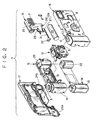
- the housing 3 is constituted by a main body 12, an exposure unit 13, a photo film cassette 14, a flash circuit board 15, a front cover 16 and a rear cover 17.
- the main body 12, the exposure unit 13, the front cover 16 and the rear cover 17 are formed respectively from resin.
- a light-shielding tunnel 18 is disposed in the center of the main body 12.
- the cassette holder chamber 19 contains a cassette 21 of the photo film cassette 14.
- the roll holder chamber 20 contains a photo film 22 drawn from the cassette 21 and wound again in a roll shape.
- the rear cover 17 is retained on the rear of the main body 12, and covers the rear of the cassette holder chamber 19 and the roll holder chamber 20. Bottom openings of the cassette holder chamber 19 and the roll holder chamber 20 are closed in a light-tight manner by bottom lids 24a and 24b formed with the rear cover 17.
- the exposure unit 13 includes the taking lens 9, a photo film wind-blocking mechanism and a shutter mechanism, and is retained on the front of the light-shielding tunnel 18 by use of engagement of claws.
- the flash circuit board 15 is retained on an outer face of the roll holder chamber 20 by use of engagement of claws.
- the exposure unit 13 and the flash circuit board 15 are covered by the front cover 16, which is retained on the front of the main body 12 by use of engagement of claws.
- a circuit pattern is printed on the front face of a board part of the flash circuit board 15, and constitutes a flash circuit.
- the flash emitter 7 is mounted in a gap formed in the right-hand upper corner of the flash circuit board 15.
- a main capacitor 25 is disposed in a position behind the flash emitter 7, and laid horizontally.
- a battery holder 26 is constituted by a pair of battery contact parts 27 and 28, which are located on the bottom of the board part of the flash circuit board 15.
- An emission switch 29 is positioned above the battery contact part 27. Those parts are soldered to the circuit pattern at solder lands on the board part of the flash circuit board 15.
- a dry battery 30 of the UM-3 type is held in the battery holder 26 as a power source of the flash circuit.
- An arm portion 31 is included in the battery contact part 27, and extends horizontally in parallel with the board part of the flash circuit board 15.
- a contact end portion 32 is disposed on the arm portion 31 by bending the piece for the battery contact part 27, has a trapezoidal shape, and is located near to the cassette holder chamber 19.
- the battery contact part 28 is located near to the roll holder chamber 20.
- the battery 30 has positive and negative terminals. A protruding end of the positive terminal is inserted in an end opening of the battery contact part 28.
- the negative terminal is positioned on the contact end portion 32, and held by resiliency of the battery contact parts 27 and 28. Thus the battery 30 is kept laid horizontally under the light-shielding tunnel 18.
- the remaining end of the arm portion 31 of the battery contact part 27 has an end region of a rectangular quadrilateral extending horizontally.
- Insertion projections 33, 34 and 35 are formed to protrude from a top edge and lateral ends of the rectangular quadrilateral end region by bending the piece for the battery contact part 27.
- Insertion holes 36, 37 and 38 are formed in the flash circuit board 15 in positions for receiving the insertion projections 33-35.
- the insertion projections 33-35 determine the position of the battery contact part 27 by insertion into the insertion holes 36-38 in the flash circuit board 15.
- solder 40 is placed between the insertion projection 33 and the inside of the insertion hole 36 to attach the battery contact part 27 to the board part of the flash circuit board 15.
- a slit 33a is formed in the center of the insertion projection 33, and receives a small part of the solder 40.
- the winder wheel 5 is rotated to set a frame of the photo film and charge the shutter device. Then the shutter release button 6 is depressed while a photographic object is observed through the viewfinder 10. A blade of the shutter mechanism is actuated to expose the photo film 22.
- the charger button 8 is depressed before releasing operation, to start charging to the main capacitor 25.
- the shutter release button 6 is depressed. Then the shutter blade is actuated.
- the two metal plate segments of the emission switch 29 contact each other, to cause the flash emitter 7 to emit flash light.
- Exposures are taken to the photo film 22, the entirety of which is wound into the cassette 21.
- the lens-fitted photo film unit being used is forwarded to a photo laboratory.
- the bottom lid 24a of the cassette holder chamber 19 is opened to remove the photo film cassette 14 with the exposed photo film 22 from the cassette holder chamber 19.
- the lens-fitted photo film unit 2 from which the photo film cassette 14 has been removed, is withdrawn by the manufacturer, and disassembled into the parts.
- the front cover 16, the rear cover 17 and the main body 12 are pelleted, and regenerated as raw material to be reused for new parts of resin.
- the exposure unit 13 is subjected to inspection of appearance and performance. Some of the parts of the exposure unit 13 are renewed, such as a shutter-driving spring, a wind-blocking lever, the taking lens 9 and the like. Then the exposure unit 13 is transferred to an assembly line of lens-fitted photo film units, to be reused.
- the flash circuit board 15 after the battery 30 is removed, is "subjected to inspection of the appearance and performance.
- the flash circuit board 15 detected acceptable is transferred to the assembly line of lens-fitted photo film units.
- a new dry battery 30 is mounted into the battery holder 26, to reuse the flash circuit board 15. If the flash circuit board 15 is detected unacceptable, the flash circuit board 15 is transferred to a reconstructing line.
- the battery contact part 27 has a smaller thickness than that of the battery contact part 28. This is for the purpose of reducing a back-to-front thickness of the lens-fitted photo film unit 2, and also keeping resiliency for good removability of the battery 30. In the course of removal of the battery 30, it is likely that the arm portion 31 is deformed considerably, to cause failure in mounting of another dry battery 30. In view of this, a part exchanging apparatus 50 in the reconstructing line is used, to which the flash circuit board 15 with the battery contact part 27 deformed is transferred for the purpose of recycling the flash circuit board 15. See Figs. 5A and 5B.
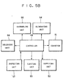
- the part exchanging apparatus 50 is constituted by an endless track conveyor 51 having a loop-shaped track, and includes a supplying unit 52, an ejecting unit 53, an eliminating unit 54, an assembling unit 55, a soldering unit 56 and an inspecting unit 57, all of which are disposed along a track of the endless track conveyor 51.
- the endless track conveyor 51 is provided with a plurality of board holders 60 or pallets respectively for supporting the flash circuit board 15.
- the board holders 60 are circulated in the loop-shaped track of the endless track conveyor 51.
- Each of the board holders 60 keeps one circuit board 15 positioned in an orientation of directing the battery contact part 27 outwards in relation to the loop-shaped track.
- the endless track conveyor 51 operates to convey the flash circuit board 15 to the eliminating unit 54, the assembling unit 55 and then the soldering unit 56 together with each of the board holders 60.
- a controller 48 in Fig. 5B controls conveyance of the board holders 60.
- the board holders 60 are caused by the controller 48 to move intermittently and stopped at the units for the part exchange, inspection, supply and withdrawal, but not at the inspecting unit 57.
- a top face of the board holders 60 has a recess for receiving rear protruding portions of the flash circuit board 15, such as the main capacitor 25.
- the flash circuit board 15 is kept extended horizontally with the front face of the printed circuit pattern directed upwards.
- the supplying unit 52 includes a supply robot 62, which removes the flash circuit board 15 from a pallet 61 before the exchange of the battery contact part 27, and places the flash circuit board 15 on the board holder 60 in the unoccupied state.
- the pallet 61 has been moved from a circuit board inspection line to the supplying unit 52.
- the flash circuit board 15 is placed on the pallet 61 in the circuit board inspection line, and transferred by the pallet 61 to the supplying unit 52.
- the ejecting unit 53 includes an ejection robot 63, which ejects the flash circuit board 15 including the new battery contact part 27.
- a pallet 65 is disposed to receive the flash circuit board 15 removed from the board holder 60, and is ready to move to the assembly line.
- the eliminating unit 54 includes a melter robot 67, a shifter robot arm 68 or robot hand, and a receptacle 69.
- the melter robot 67 has a hot air heater 66 for blowing with hot air to the solder 40 in connection between the battery contact part 27 and the board part of the flash circuit board 15.
- the shifter robot arm 68 captures the battery contact part 27 while the solder 40 is melted, and removes the battery contact part 27 from the board part.
- the receptacle 69 receives the battery contact part 27 removed by the shifter robot arm 68.
- the assembling unit 55 is constituted by an assembly robot 72 and a supply conveyor 73.
- the assembly robot 72 mounts the new battery contact part 27 on to the board part of the flash circuit board 15 from which the battery contact part 27 has been removed.
- the supply conveyor 73 supplies the assembly robot 72 with the battery contact part 27.
- Plural battery contact parts 27 are arranged in line by a hopper device (not shown), and disposed on the supply conveyor 73.
- the assembly robot 72 captures the foremost one of the battery contact part 27.
- a soldering robot 75 constitutes the soldering unit 56 to solder the flash circuit board 15 with the battery contact part 27 newly placed by the supplying unit 52.
- the soldering robot 75 has a soldering iron 75a and a solder cartridge 75b.
- the solder cartridge 75b contains a roll of solder wire.
- the soldering iron 75a is automatically supplied with the solder wire by the solder cartridge 75b. If all the solder wire is used up, the solder cartridge 75b is replaced with an unused solder cartridge.
- a contact plate 77 is disposed in the inspecting unit 57 for being depressed by contacting the flash circuit board 15 in the course of movement of the flash circuit board 15 past the inspecting unit 57. An amount of depression of the contact plate 77 is checked to detect the amount of looseness with which the battery contact part 27 is mounted in an upwards projecting state on the board part of the flash circuit board 15.
- the supply robot 62 stands by on the loop-shaped track while grasping the flash circuit board 15 removed from the pallet 61.
- the supply robot 62 mounts the flash circuit board 15 on the board holder 60, which has been unoccupied and positioned in the supplying unit 52 provisionally.
- the board holder 60 with the flash circuit board 15 is transferred to the eliminating unit 54, and stopped temporarily in a predetermined position.
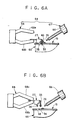
- an air outlet 70 of the hot air heater 66 is directed to the center of the solder 40 connecting the battery contact part 27 and the board part of the flash circuit board 15 while the board holder 60 is stopped.
- the shifter robot arm 68 is moved to the battery contact part 27.
- a capturing claw 68a of the shifter robot arm 68 comes to a position above the battery contact part 27.
- a capturing claw 68b is inserted between the flash circuit board 15 and the battery contact part 27 in a direction toward the insertion projection 33.
- the hot air heater 66 causes hot air to flow through the air outlet 70 toward the solder 40, which is heated and melted.
- the air outlet 70 has a size smaller than an area of the solder 40. Thus the hot air is applied only to the solder 40, which can be melted with much efficiency.
- the capturing claws 68a and 68b of the shifter robot arm 68 grasp the battery contact part 27 as the capturing claw 68b lifts the battery contact part 27 directly in a vertical direction.
- the insertion projections 33-35 are pulled out of the insertion holes 36-38.
- the battery contact part 27 is eliminated from the flash circuit board 15. Note that there is constantly preheating operation for the hot air heater 66 to give off hot air instantaneously. It is possible to apply heat by blowing with hot air immediately upon the stop of the board holder 60.
- the battery contact part 27 is lifted while hot air is applied to the center of the solder 40.
- a regular small amount of solder remains on the flash circuit board 15 while another part of the solder 40 remains in the slit 33a of the insertion projection 33.
- the regular small amount of the solder makes it possible to simplify the soldering process by eliminating a step of placing additional solder on the flash circuit board 15 for resoldering the battery contact part 27.
- the battery contact part 27 being removed is shifted by the shifter robot arm 68 and entered into the receptacle 69.
- the battery contact part 27 collected in the receptacle 69 is regenerated as raw material, and is recycled for new metal parts.
- the board holder 60 and the board part of the flash circuit board 15 without the battery contact part 27 is transferred to the assembling unit 55, and stopped provisionally in a predetermined position.
- the assembly robot 72 is ready on the track while holding a new battery contact part 27, which is placed on the board part of the flash circuit board 15 being stopped.
- the insertion projections 33-35 are inserted into the insertion holes 36-38, to position the battery contact part 27 temporarily.
- the board holder 60 with the flash circuit board 15, on which the new battery contact part 27 is positioned, is transferred to the soldering unit 56 and stopped temporarily in a predetermined position.
- the soldering robot 75 moves the soldering iron 75a to the insertion projection 33, to solder the battery contact part 27 to the board part, to obtain a reconstructed flash circuit board 15.
- the contact plate 77 contacts the flash circuit board 15 to inspect whether the battery contact part 27 is loosely mounted in an upwards projecting state. If the flash circuit board 15 is detected acceptable in a fixedly attached state, the board holder 60 with the flash circuit board 15 is transferred to the ejecting unit 53, and stopped in a predetermined position temporarily. The flash circuit board 15 is removed by the ejection robot 63 from the board holder 60, and placed to the pallet 65.
- the reconstructed flash circuit board 15 on the pallet 65 is transferred to the assembly line, where the flash circuit board 15 is mounted on the new main body 12 to be reused.
- the board holder 60, from which the flash circuit board 15 is removed, is conveyed by the endless track conveyor 51 to the supplying unit 52.
- the flash circuit board 15, if detected unacceptable by the inspecting unit 57, is not withdrawn by the ejection robot 63, but is conveyed to the eliminating unit 54 by the endless track conveyor 51. Again, the battery contact part 27 of the flash circuit board 15 is replaced with a new one in the same process as described above.
- the operation of the supply and withdrawal of the flash circuit board 15 is effected automatically by use of the endless track conveyor 51, the supplying unit 52 and the ejecting unit 53. It is possible to reduce the total of laborious manual operation to what is required for an overall administration of the apparatus. Thus the manual operation for the exchange of the part can be much easier.
- hot air is applied to the center of the solder connecting the battery contact part and the board part, so that a regular small amount of the solder remains on the flash circuit board 15 while another part of the solder 40 remains in the slit 33a of the insertion projection 33.
- hot air may be applied to a position under the center of the solder or on a surface of the board part. The entirety of the solder may remain with the battery contact part, and may be neatly removed from the board part.
- the solder of the partial amount remains on the board part after the elimination of the battery contact part, and is usable again for the attachment.
- the solder cartridge 75b may be eliminated, because no additional solder may be supplied.
- the eliminating unit includes the hot air heater.
- an eliminating unit may have a combination of a soldering iron and a suction device.
- the soldering iron may melt the solder, before the suction device may suck and eliminate the melted solder.
- the soldering unit includes the soldering iron.
- a soldering unit may have a combination of a hot air heater and a solder cartridge. Solder wire may be supplied by the solder cartridge. Hot air heater may apply hot air to the solder wire, so as to solder the battery contact part to the board part.
- the endless track conveyor 51 is used.
- any type of conveyor can be used, for example, an indexing table which is shaped circularly and rotatable, a live roller conveyor having a great number of rollers rotating in synchronism, a pallet conveyor inclusive of the board holders as pallets, a car type of conveyor inclusive of the board holders as cars, and any suitable conveyor in which the board holder 60 can be conveyed along a track with a shape of a closed loop.
- two conveyors with paths of a simple straight type such as belt conveyors and chain conveyors, can be used, and arranged in parallel and driven in direction reverse to each other, with necessary addition of manual operation or auxiliary robot hands for transferring the board part of the circuit board with each board holder from one conveyor to the another.
- the one sequence of the exchange of the battery contact part 27 is effected in the course of one cyclic operation of the endless track conveyor 51. Furthermore it is possible to effect plural sequences of the exchange of the battery contact part 27 in the course of one cyclic operation of the endless track conveyor 51.
- the conveyor of the part exchanging apparatus can be an extended portion of a conveyor of an inspection line or assembly line for the circuit board.
- the conveyor of the part exchanging apparatus may be provided with a positioning robot arm or robot hand for keeping the flash circuit board 15 positioned.
- the conveyor may be eliminated from the part exchanging apparatus, for which manual operation may be added for supplying the circuit board for the eliminating, assembling and soldering units. This is effective in lowering cost required for constructing the part exchanging apparatus.
- the assembling unit 55 is disposed downstream from the eliminating unit 54.
- the soldering unit 56 is disposed downstream from the assembling unit 55.
- the eliminating unit 54 and the assembling unit 55 may be disposed in the same station relative to the conveying path, and may be movable into and out of one space of the station alternately, to access the board part of the flash circuit board 15 successively.
- the assembling unit 55 and the soldering unit 56 may be disposed in the same station, and may be movable into and out of one space of the station alternately, to access the board part successively.
- the part exchanging apparatus is designed for exchanging the battery contact part of the flash circuit board incorporated in the lens-fitted photo film unit.
- a part exchanging apparatus of the present invention can be constructed for exchanging the main capacitor, the flash emitter, or any suitable soldered part of the flash circuit board, and also constructed for exchanging an electrical part of any device in the field of electricity that is soldered to another part of the device.
Landscapes
- Engineering & Computer Science (AREA)
- Mechanical Engineering (AREA)
- Physics & Mathematics (AREA)
- General Physics & Mathematics (AREA)
- Manufacturing & Machinery (AREA)
- Microelectronics & Electronic Packaging (AREA)
- Electric Connection Of Electric Components To Printed Circuits (AREA)
- Structure And Mechanism Of Cameras (AREA)
- Supply And Installment Of Electrical Components (AREA)
Claims (15)
- Appareil d'échange de partie pour une carte de circuit (15), comprenant :caractérisé en ce que ladite unité d'élimination (54), ladite unité d'assemblage (55), ladite unité de soudure (56) sont disposées en séquence en référence à un convoyeur (51) pour convoyer ladite carte de circuit (15) le long d'un trajet de convoyage prédéterminé.une partie de carte comprise dans ladite carte de circuit, au moins une première partie (27) raccordée à ladite partie de carte par une soudure (40) ; une unité d'élimination (54) pour faire fondre ladite soudure et enlever ladite première partie (27) de ladite partie de carte alors que ladite soudure est fondue ; une unité d'assemblage (55) pour monter une seconde partie (27) sur ladite partie de carte fournie par ladite unité d'élimination (54) afin de substituer ladite première partie (27) ; et une unité de soudure (56) pour raccorder ladite seconde partie (27) à ladite carte fournie par ladite unité d'assemblage (55) en utilisant une soudure,
- Appareil d'échange de partie selon la revendication 1,
caractérisé en ce que ledit trajet de convoyage est en forme de boucle, et ledit trajet de circuit (15) est déplaçable par ledit convoyeur (51) le long dudit trajet de convoyage. - Appareil d'échange de partie selon la revendication 1 ou 2,
caractérisé par une unité d'alimentation (52) disposée en amont de ladite unité d'élimination (54) en référence audit trajet de convoyage pour fournir audit trajet de convoyage ladite carte de circuit (15), et une unité d'éjection (53) disposée en aval de ladite unité de soudure (56) en référence audit trajet de convoyage pour éjecter ladite partie de carte et ladite seconde partie (27) soudée à celle-ci à partir dudit trajet de convoyage. - Appareil d'échange de partie selon au moins une des revendications précédentes 1 à 3,
caractérisé par un support de carte (60) sur lequel ladite partie de carte est montée, et qui est monté cycliquement le long dudit trajet de convoyage par ledit convoyeur (51), où lesdites première et seconde parties (27) sont enlevées ou montées alors que ladite partie de carte est montée sur ledit support de carte (60). - Appareil d'échange de partie selon la revendication 3,
caractérisé par une unité de contrôle (57) disposée entre ladite unité de soudure (56) et ladite unité d'éjection (53) le long dudit trajet de convoyage pour déterminer si un état monté entre ladite partie de carte et ladite seconde partie (27) est acceptable. - Appareil d'échange de partie selon la revendication 5,
caractérisé en ce que la première partie (27) est une des première et seconde parties de contact de batterie (27, 28) utilisée, et la seconde partie (27) est une des première et seconde parties de contact de batterie (27, 28) inutilisée, où ladite première partie de contact de batterie (27) a des première et seconde extrémités (32, 33 à 35), ladite seconde partie de contact de batterie (28) a des troisième et quatrième extrémités, lesdites première et troisième extrémités (32) sont raccordées à ladite partie de carte, lesdites seconde et quatrième extrémités (33, 35) sont adaptées pour être en contact avec les électrodes d'une batterie (30). - Appareil d'échange de batterie selon la revendication 5 ou 6,
caractérisé par un dispositif de commande (48) pour commander ledit convoyeur (51) et ladite unité d'éjection (53) selon la détermination par ladite unité de contrôle (57), où ledit dispositif de commande est adapté pour entraíner ladite unité d'éjection (53) si ledit état monté est acceptable, et pour induire ledit convoyeur (51) à convoyer ladite carte de circuit (15) devant ladite unité d'éjection (53) pour alimenter ladite unité d'élimination (54) avec celle-ci. - Appareil d'échange de partie selon au moins une des revendications précédentes 1 à 7,
caractérisé en ce que ladite carte de circuit (15) est une carte de circuit flash (15) d'une unité de film photo pourvue d'un objectif (2). - Appareil d'échange de partie selon au moins une des revendications précédentes 1 à 8,
caractérisé en ce que ladite unité d'élimination (54) comprend un élément chauffant (66) pour faire fondre la soudure (40) de ladite première partie (27) par application du chauffage, et un dispositif de décalage (68) pour éloigner ladite première partie (27) de ladite partie de carte lorsque ladite soudure (40) est fondue. - Appareil d'échange de partie selon la revendication 9,
caractérisé en ce que ledit élément chauffant (66) est un élément chauffé à l'air chaud pour appliquer de l'air chaud à ladite soudure (40) de ladite première partie (27). - Appareil d'échange de partie selon au moins une des revendications précédentes 1 à 10,
caractérisé en ce que ledit convoyeur (51) est un convoyeur sans fin. - Procédé d'échange de partie pour une carte de circuit (15) comprenant une partie de carte, et au moins une première partie (27) raccordée à ladite partie de carte par une soudure (40), comprenant les étapes de :fusion de ladite soudure sur une première unité ;enlèvement de ladite première partie à partir de ladite partie de carte sur une seconde unité alors que ladite soudure est fondue ;montage d'une seconde partie (27) sur ladite partie de carte sur une troisième unité, afin de substituer ladite première partie ;raccordement de ladite seconde partie à ladite partie de carte par l'utilisation d'une soudure sur une quatrième unité ; etconvoyage de ladite partie de carte à partir de ladite première unité à ladite quatrième unité dans l'ordre par un convoyeur.
- Procédé d'échange de partie selon la revendication 12,
caractérisé en ce que ladite carte de circuit (15) est une carte de circuit flash (15) d'une unité de film photo pourvue d'une lentille (2). - Procédé d'échange de partie selon la revendication 12 ou 13,
caractérisé par l'étape de :détermination si un état monté entre ladite partie de carte et ladite seconde partie (27) est acceptable. - Procédé d'échange de partie selon la revendication 14,
caractérisé par les étapes de :commande d'une unité d'éjection (53) si ledit état monté est acceptable ;convoyage de ladite carte de circuit (15) devant ladite unité d'éjection (53) si ledit état monté est inacceptable et fourniture d'une unité d'élimination (54) avec celle-ci.
Applications Claiming Priority (2)
| Application Number | Priority Date | Filing Date | Title |
|---|---|---|---|
| JP10101057A JPH11298137A (ja) | 1998-04-13 | 1998-04-13 | 回路基板の部品交換装置 |
| JP10105798 | 1998-04-13 |
Publications (2)
| Publication Number | Publication Date |
|---|---|
| EP0950920A1 EP0950920A1 (fr) | 1999-10-20 |
| EP0950920B1 true EP0950920B1 (fr) | 2002-12-18 |
Family
ID=14290496
Family Applications (1)
| Application Number | Title | Priority Date | Filing Date |
|---|---|---|---|
| EP99107112A Expired - Lifetime EP0950920B1 (fr) | 1998-04-13 | 1999-04-12 | Dispositif et procédé pour remplacer des composants sur un circuit imprimé d'un appareil photo réutilisable |
Country Status (4)
| Country | Link |
|---|---|
| US (1) | US6634092B1 (fr) |
| EP (1) | EP0950920B1 (fr) |
| JP (1) | JPH11298137A (fr) |
| DE (1) | DE69904526T2 (fr) |
Families Citing this family (13)
| Publication number | Priority date | Publication date | Assignee | Title |
|---|---|---|---|---|
| JP4849751B2 (ja) * | 2001-09-06 | 2012-01-11 | パナソニック株式会社 | 部品実装装置及び部品実装方法 |
| US6945447B2 (en) * | 2002-06-05 | 2005-09-20 | Northrop Grumman Corporation | Thermal solder writing eutectic bonding process and apparatus |
| TW542819B (en) * | 2002-07-26 | 2003-07-21 | Hannstar Display Corp | Half-square welding processing system with multiple feeding lines |
| WO2008085158A2 (fr) * | 2007-01-09 | 2008-07-17 | Tandis Inc. | Système de transport sans contact pour la production de cartes intelligentes |
| JP5003350B2 (ja) * | 2007-08-23 | 2012-08-15 | パナソニック株式会社 | 電子部品実装装置および電子部品実装方法 |
| JP5606136B2 (ja) * | 2010-04-26 | 2014-10-15 | 富士機械製造株式会社 | 部品実装機 |
| EP2793092B1 (fr) * | 2013-08-26 | 2015-07-08 | Advanced Digital Broadcast S.A. | Système de ligne d'assemblage, procédé et appareil de réduction du nombre de stations de travail d'assemblage |
| CN104551291A (zh) * | 2013-10-21 | 2015-04-29 | 泰科电子(上海)有限公司 | 自动焊接系统 |
| CN109590567B (zh) * | 2017-10-02 | 2021-11-26 | 白光株式会社 | 焊接装置以及程序的制作方法 |
| CN107915047B (zh) * | 2017-12-21 | 2023-11-17 | 东莞科耀机电设备有限公司 | 一种pcb板用上下板机 |
| JP2020032320A (ja) * | 2018-08-27 | 2020-03-05 | コベルコ建機株式会社 | 解体システム |
| JP7075498B2 (ja) * | 2018-10-02 | 2022-05-25 | 株式会社Fuji | 作業機 |
| DE102024127577A1 (de) * | 2024-09-24 | 2026-03-26 | Repartly GmbH | Verfahren zum selbsttätigen Reparieren von Elektroniken und Reparatursystem für Elektroniken |
Family Cites Families (14)
| Publication number | Priority date | Publication date | Assignee | Title |
|---|---|---|---|---|
| US4845843A (en) * | 1985-10-28 | 1989-07-11 | Cimm, Inc. | System for configuring, automating and controlling the test and repair of printed circuit boards |
| US4813589A (en) * | 1988-04-05 | 1989-03-21 | Palmer Harold D | Surface mounted device rework heat guide |
| JPH01295500A (ja) * | 1988-05-24 | 1989-11-29 | Taiyo Yuden Co Ltd | チップ状電子部品マウント方法及びその装置 |
| US4954453A (en) * | 1989-02-24 | 1990-09-04 | At&T Bell Laboratories | Method of producing an article comprising a multichip assembly |
| FR2657218A1 (fr) * | 1990-01-12 | 1991-07-19 | Radiotechnique Compelec | Dispositif de positionnement pour la fabrication de circuits imprimes. |
| EP0497129B1 (fr) * | 1991-01-28 | 1995-07-26 | Siemens Aktiengesellschaft | Dispositif pour équiper des plaquettes de circuits |
| JP2594061Y2 (ja) * | 1991-04-15 | 1999-04-19 | 富士写真光機株式会社 | レンズ付きフイルムユニット |
| US5152056A (en) * | 1991-08-27 | 1992-10-06 | Sun Microsystems, Inc. | Method for replacing tape automated bonding components on a printed circuit board |
| DE4332236A1 (de) * | 1992-11-26 | 1995-03-23 | F E S Used Electronics Elektro | Anlage zur automatischen Entstückung |
| US5608486A (en) * | 1993-03-03 | 1997-03-04 | Fuji Photo Film Co., Ltd. | Lens-fitted photographic film package |
| US5601675A (en) * | 1994-12-06 | 1997-02-11 | International Business Machines Corporation | Reworkable electronic apparatus having a fusible layer for adhesively attached components, and method therefor |
| DE19504517C1 (de) * | 1995-02-11 | 1996-08-08 | Atotech Deutschland Gmbh | Verfahren zum Galvanisieren von plattenförmigem Behandlungsgut in horizontalen Durchlaufanlagen sowie Vorrichtung zur Durchführung des Verfahrens |
| JPH08236989A (ja) * | 1995-02-28 | 1996-09-13 | Nippondenso Co Ltd | 部品供給装置 |
| US5680936A (en) * | 1995-03-14 | 1997-10-28 | Automated Technologies Industries, Inc. | Printed circuit board sorting device |
-
1998
- 1998-04-13 JP JP10101057A patent/JPH11298137A/ja active Pending
-
1999
- 1999-04-12 DE DE69904526T patent/DE69904526T2/de not_active Expired - Lifetime
- 1999-04-12 EP EP99107112A patent/EP0950920B1/fr not_active Expired - Lifetime
- 1999-04-13 US US09/290,201 patent/US6634092B1/en not_active Expired - Lifetime
Also Published As
| Publication number | Publication date |
|---|---|
| JPH11298137A (ja) | 1999-10-29 |
| EP0950920A1 (fr) | 1999-10-20 |
| US6634092B1 (en) | 2003-10-21 |
| DE69904526D1 (de) | 2003-01-30 |
| DE69904526T2 (de) | 2003-05-15 |
Similar Documents
| Publication | Publication Date | Title |
|---|---|---|
| EP0950920B1 (fr) | Dispositif et procédé pour remplacer des composants sur un circuit imprimé d'un appareil photo réutilisable | |
| JP2594061Y2 (ja) | レンズ付きフイルムユニット | |
| JPH05507367A (ja) | フィルムパック使い捨てカメラ及びそれに用いる印刷回路板組立体 | |
| US5615395A (en) | Method and apparatus for disassembling lens-fitted photo film unit, and flash cleaning method and apparatus | |
| US7082263B2 (en) | Lens-fitted photo film unit, flash device, and lens-fitted photo film system | |
| JPH06161053A (ja) | 包装体の分離方法 | |
| JP3135092B2 (ja) | レンズ付きフイルムユニットの分解方法 | |
| US6208807B1 (en) | Method and apparatus for disassembling lens-fitted photo film unit | |
| EP1624335B1 (fr) | Dispositif de démontage pour des appareils photo reutilisables et son procédé | |
| JP3135093B2 (ja) | レンズ付きフイルムユニットのストロボ発光面清浄化方法 | |
| JP3260129B2 (ja) | レンズ付きフイルムユニット用ストロボ装置の再使用方法 | |
| JPH06175295A (ja) | レンズ付きフイルムユニットの分解検査方法 | |
| EP0829763B1 (fr) | Appareil de traitement photographique | |
| JP2005063853A (ja) | 電池取外し方法及びそれを用いたレンズ付きフイルムユニットの分解方法並びに分解装置 | |
| JP2005062564A (ja) | レンズ付きフイルムユニットの分解方法及び装置 | |
| JPH08122979A (ja) | ストロボ装置の発光面洗浄方法 | |
| JP3413292B2 (ja) | レンズ付きフイルムユニット | |
| JPH10177239A (ja) | レンズ付きフイルムユニット用ストロボ装置の部品供給装置及び部品供給方法 | |
| JP2004117898A (ja) | レンズ付きフイルムユニット | |
| JPH10142766A (ja) | 写真処理装置 | |
| JPH07114069A (ja) | 再使用されるストロボユニットの修正方法 | |
| JP2000081654A (ja) | レンズ付フィルムユニットおよびその製造方法 | |
| JPH10254029A (ja) | ストロボ装置 | |
| JP2004012709A (ja) | レンズ付きフイルムユニット | |
| JPH04120959U (ja) | レンズ付きフイルムユニツト |
Legal Events
| Date | Code | Title | Description |
|---|---|---|---|
| PUAI | Public reference made under article 153(3) epc to a published international application that has entered the european phase |
Free format text: ORIGINAL CODE: 0009012 |
|
| AK | Designated contracting states |
Kind code of ref document: A1 Designated state(s): DE |
|
| AX | Request for extension of the european patent |
Free format text: AL;LT;LV;MK;RO;SI |
|
| 17P | Request for examination filed |
Effective date: 20000310 |
|
| AKX | Designation fees paid |
Free format text: DE |
|
| 17Q | First examination report despatched |
Effective date: 20000918 |
|
| GRAG | Despatch of communication of intention to grant |
Free format text: ORIGINAL CODE: EPIDOS AGRA |
|
| GRAG | Despatch of communication of intention to grant |
Free format text: ORIGINAL CODE: EPIDOS AGRA |
|
| GRAG | Despatch of communication of intention to grant |
Free format text: ORIGINAL CODE: EPIDOS AGRA |
|
| GRAH | Despatch of communication of intention to grant a patent |
Free format text: ORIGINAL CODE: EPIDOS IGRA |
|
| GRAH | Despatch of communication of intention to grant a patent |
Free format text: ORIGINAL CODE: EPIDOS IGRA |
|
| GRAA | (expected) grant |
Free format text: ORIGINAL CODE: 0009210 |
|
| AK | Designated contracting states |
Kind code of ref document: B1 Designated state(s): DE |
|
| REF | Corresponds to: |
Ref document number: 69904526 Country of ref document: DE Date of ref document: 20030130 Kind code of ref document: P Ref document number: 69904526 Country of ref document: DE Date of ref document: 20030130 |
|
| PLBE | No opposition filed within time limit |
Free format text: ORIGINAL CODE: 0009261 |
|
| STAA | Information on the status of an ep patent application or granted ep patent |
Free format text: STATUS: NO OPPOSITION FILED WITHIN TIME LIMIT |
|
| 26N | No opposition filed |
Effective date: 20030919 |
|
| PGFP | Annual fee paid to national office [announced via postgrant information from national office to epo] |
Ref country code: DE Payment date: 20150408 Year of fee payment: 17 |
|
| REG | Reference to a national code |
Ref country code: DE Ref legal event code: R119 Ref document number: 69904526 Country of ref document: DE |
|
| PG25 | Lapsed in a contracting state [announced via postgrant information from national office to epo] |
Ref country code: DE Free format text: LAPSE BECAUSE OF NON-PAYMENT OF DUE FEES Effective date: 20161101 |