EP0951994B1 - Dispositif de fixation de plaques sur des cylindres de machines à impression - Google Patents
Dispositif de fixation de plaques sur des cylindres de machines à impression Download PDFInfo
- Publication number
- EP0951994B1 EP0951994B1 EP99106998A EP99106998A EP0951994B1 EP 0951994 B1 EP0951994 B1 EP 0951994B1 EP 99106998 A EP99106998 A EP 99106998A EP 99106998 A EP99106998 A EP 99106998A EP 0951994 B1 EP0951994 B1 EP 0951994B1
- Authority
- EP
- European Patent Office
- Prior art keywords
- lever
- fixing device
- plate
- clamping rail
- actuation device
- Prior art date
- Legal status (The legal status is an assumption and is not a legal conclusion. Google has not performed a legal analysis and makes no representation as to the accuracy of the status listed.)
- Expired - Lifetime
Links
- 230000001960 triggered effect Effects 0.000 claims description 2
- 238000007493 shaping process Methods 0.000 claims 1
- 238000001514 detection method Methods 0.000 description 15
- 238000000034 method Methods 0.000 description 6
- 230000004913 activation Effects 0.000 description 3
- 230000006378 damage Effects 0.000 description 3
- 238000003780 insertion Methods 0.000 description 3
- 230000037431 insertion Effects 0.000 description 3
- 238000004519 manufacturing process Methods 0.000 description 2
- 238000012544 monitoring process Methods 0.000 description 2
- 230000001953 sensory effect Effects 0.000 description 2
- 102000001999 Transcription Factor Pit-1 Human genes 0.000 description 1
- 108010040742 Transcription Factor Pit-1 Proteins 0.000 description 1
- 230000003213 activating effect Effects 0.000 description 1
- 238000013461 design Methods 0.000 description 1
- 238000011161 development Methods 0.000 description 1
- 230000018109 developmental process Effects 0.000 description 1
- 230000007257 malfunction Effects 0.000 description 1
- 238000011144 upstream manufacturing Methods 0.000 description 1
Images


Classifications
-
- B—PERFORMING OPERATIONS; TRANSPORTING
- B41—PRINTING; LINING MACHINES; TYPEWRITERS; STAMPS
- B41F—PRINTING MACHINES OR PRESSES
- B41F27/00—Devices for attaching printing elements or formes to supports
- B41F27/12—Devices for attaching printing elements or formes to supports for attaching flexible printing formes
- B41F27/1218—Devices for attaching printing elements or formes to supports for attaching flexible printing formes comprising printing plate tensioning devices
- B41F27/1225—Devices for attaching printing elements or formes to supports for attaching flexible printing formes comprising printing plate tensioning devices moving in the printing plate end substantially rectilinearly
- B41F27/1231—Devices for attaching printing elements or formes to supports for attaching flexible printing formes comprising printing plate tensioning devices moving in the printing plate end substantially rectilinearly by translatory motion substantially tangential to support surface
Definitions
- the invention relates to a fastening device for Plates on printing press cylinders according to the preamble of Claim 1.
- a disadvantage of such a device is that the Holding force for the spring elements applying the pressure plates arranged integrated in the rails of the clamping device must be so that the manufacture of the corresponding parts a high manufacturing cost.
- the spring elements there is an automatic adjustment to different ones Plate thicknesses, however, the detection gap for the pressure plate because of the overpressure of the springs when opening the clamping device only opened up to a maximum amount become.
- a small detection gap makes insertion difficult of the pressure plate end in such a clamping device. At An automated plate feeder is therefore a malfunction cannot be excluded in the course of the procedure.
- a clamping device for printing plates in which an upper and a lower terminal block over a rotatable cam or eccentric shaft in an open and in a closed position holding the pressure plate can be brought is.
- the cam or eccentric shaft is on the led out and faces both ends of the cylinder Lever elements, each with an example as Pneumatic cylinder trained actuator interact.
- the clamping device is opened by loading the other actuator closing the Clamping device and thus the clamping of the pressure plate.
- a Device to avoid damage to the clamping device or actuators in the event that objects too thick in the open detection area the clamping rail are in this known device however not provided.
- the object of the present invention is therefore a fastening device according to the preamble of claim 1 to expand in such a way that avoiding the above Disadvantages mentioned a structurally simple execution is obtained for a fastening device the plates can be attached with sufficient holding force are and also protection against destruction in the event detected objects is too thick.
- the preferably a fixed upper and a radially movable lower terminal block existing fastening device over a cylinder-supported and below the lower one Terminal block arranged eccentric shaft is actuated.
- the eccentric shaft is pivoted using two assigned ones Actuators such that the first Actuator the clamping rail from the closed Position in the open and from the open position (Inserting a printing plate) into one of the maximum plate thickness corresponding locking position is transferable and the complete closing and thus clamping of the plate a second actuator from this pre-closed position from, which is then used to hold the pressure plate necessary holding force is applied.
- first actuator is one compared to the full closing reduced force so that even if an object with too large is present Strength within the open detection area of the Clamping rail no damage to the corresponding parts caused. This takes place in the pre-closing position measuring the plate thickness - the final closing only occurs when a plate with the maximum is determined allowable or less strength.
- Activation of the first and second actuators is such that the second, the final Holding force for the actuator applying the pressure plate is only activated if after activation the first actuator the lower terminal block from the open position completely the intended and the maximum workable plate thickness corresponding pre-closing position has reached. If by mistake a wrong one Object (e.g. tool) or a pressure plate with too large thickness (e.g. folded edge / corner) in the open Detection area between the upper and lower terminal strips has been introduced, the lower terminal block reaches after activating the first actuator the lower closing force not that of the maximum processable Pre-position corresponding to plate thickness.
- Object e.g. tool
- too large thickness e.g. folded edge / corner
- the achievement the pre-closing position corresponding to the maximum plate thickness by one with the first actuator interacting sensor is determined.
- the first Actuating device as explained in more detail below as a double-acting pneumatic cylinder designed to Approaching the pre-closing position with a reduced pressure is operated, it can be reached the pre-closing position monitor by using a sensor (Proximity switch) one on the piston rod or on one Mark made by the lever driven by the piston rod is keyed. If the plate is not too thick in the open detection gap, the activation of the first actuator representing pneumatic cylinder reached the pre-closing position and a corresponding one Sensor signal generated (extended position of the piston rod the first actuator).
- the second is applied Actuating device (double-acting pneumatic cylinder), so that the lower terminal block from the pre-closing position the force intended to hold a pressure plate in the Closed position is pressed.
- the lower terminal block moving eccentrics are in the intended end position panned.
- the fastening device according to the invention can on a Plate or form cylinder both for attaching a plate be provided at the beginning and end of the print. Especially for holding a printing plate at the end of the print are special high clamping forces required, which by appropriate Interpretation of the second actuator in simple Are feasible. Introducing the print end into the Fastening device is opened by wide opening of the clamping gap (Detection range) facilitated, so that the invention Fastening device preferred for half or fully automatic plate changing systems can be used can.
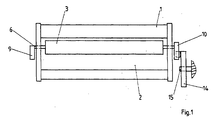
- FIG. 1 shows a plate or forme cylinder Cylinder 1 of a printing machine, not shown.
- the cylinder 1 has an axially parallel pit 2, in which is a clamping rail 3 assigned to the start of printing as Fastening device for printing plates is arranged.
- the clamping rail 3 as a fastening device has according to Figure 2 shows a cylinder-fixed upper part 4 in the form of a profiled rail and a radially movable Lower part 5, which is also designed as a rail. Below the radially movable lower part 5 runs parallel for this purpose, a cylinder-fixed in spaced from each other Bearing blocks 8 rotatably received shaft 6, which has 8 eccentrics 7 between the bearing blocks.
- the outer contours the eccentric 7 act with the lower surfaces of the Lower part 5 in the manner shown, so that by the pivoting of the shaft 6, the lower part 5 for opening or Closing the clamping gap is actuated.
- the direction of movement of the lower part 5 and the eccentric 7 are through the Double arrows indicated.
- the lower part 5 is through Spring elements, not shown, in the open position (cf. Fig. 3) and thus against the outer contour of the Eccentric 7 pressed.
- the lower part 5 pivots through this Spring elements simultaneously shaft 6 via the eccentric 7 in the "open” position. That of the first actuator 11 associated lever 10 at one end of the shaft 6 is thus rotated into the position shown in Figure 3.
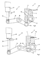
- Figures 3 to 5 show the first actuator 11, which with the lever 10 on one end of the Cylinder 1 cooperates according to Figure 1.
- the first actuator 11 consists of one at the not shown end pivotally articulated, pneumatically operated Working cylinder 12 with a piston rod 13, the free end articulated with one arm of a two-armed Lever 14 is connected.
- This lever 14 is a frame-fixed joint 15 rotatably mounted.
- the lever 14 has a rotatably mounted roller 16 on a second arm, which cooperates with a contour 17 of the lever 10 of the shaft 6.
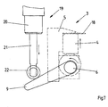
- Figure 3 shows the fully open position the clamping rail 3 with the in the lowest position located lower part 5 for inserting a pressure plate 18th in the fully open detection gap.
- FIGS 6 and 7 show that on the opposite side of the cylinder 1 arranged lever 9, which with the second Actuator 19.
- the second actuator 19 consists of a pneumatically operated, fixed arranged working cylinder 20 with a piston rod 21 the end of which a roller 22 is arranged.
- the roller 22 acts doing so with the free end of the lever 9 at the corresponding end the shaft 6 together.
- a sensor 23 is provided, which with a mark made on the shaft of the piston rod 13 24 interacts and from which a signal can be exactly extracted, when the piston rod 13 is fully extended.
- the mark 24 can be a permanent magnet with which a magnetic field detecting sensor 23 cooperates.
- a comparison of the positions of the lever 10 of Figures 3 and 4 shows that when in the detection gap between the top 4 and lower part 5 there is an object that is too thick, the lever 10 is not in the position shown in FIG. 4 can pivot and consequently the piston rod 13 because of reduced pressure in the working cylinder 12 does not fully extend. As a result, the marking 24 then lies on the sensor 23 not opposite and there is no signal from this.
- the sensor 23 stands with one of the processes shown triggering control in operative connection, the control the pressurization of the working cylinders 12, 20 over Electromagnetically switchable valves.
Landscapes
- Supply, Installation And Extraction Of Printed Sheets Or Plates (AREA)
Claims (10)
- Dispositif de fixation pour des plaques sur des cylindres de machines d'impression, en particulier, pour des clichés ou des plaques d'impression sur des cylindres porte-cliché ou porte-plaque de machines d'impression offset à feuilles, comportant une barre de serrage constituée d'une partie supérieure et d'une partie inférieure, une zone de saisie, formée entre la partie supérieure et la partie inférieure, pour la plaque, ainsi qu'un dispositif d'actionnement, au moyen duquel la zone de saisie est ouverte et, pour maintenir la plaque d'impression, est fermée,
caractérisé en ce qu'un premier dispositif d'actionnement (11) est prévu, au moyen duquel la barre de serrage fermée (3) peut être amenée à s'ouvrir et de la position ouverte dans une position de pré-fermeture, et en ce qu'un second dispositif d'actionnement (19) est prévu, au moyen duquel la barre de serrage (3) est fermée de la position de pré-fermeture par une force permettant le maintien de la plaque. - Dispositif de fixation selon la revendication 1,
caractérisé en ce que la barre de serrage (3) est constituée d'une partie supérieure (4) ainsi que d'une partie inférieure (5) radialement mobile par rapport à celle-ci, la partie inférieure (5) pouvant être actionnée, par un arbre (6), agencé en dessous, ayant des excentriques (7) prévus sur celui-ci pour l'ouverture et la fermeture. - Dispositif de fixation selon la revendication 2,
caractérisé en ce que la partie inférieure (5) peut être amenée dans la position ouverte par des éléments élastiques associés. - Dispositif de fixation selon une des revendications précédentes,
caractérisé en ce que le cylindre (1) présente, aux deux extrémités frontales, à chaque fois un levier (9, 10), le levier (10) coopérant avec le premier dispositif d'actionnement (11) et le levier (9) avec le second dispositif d'actionnement (19). - Dispositif de fixation selon la revendication 4,
caractérisé en ce que les premier et second dispositifs d'actionnement (11, 19) sont agencés de façon solidaire du bâti, de sorte que ceux-ci, après la rotation du cylindre (1) dans une position prévue, agissent sur les leviers (9, 10). - Dispositif de fixation selon une des revendications précédentes,
caractérisé en ce que le premier dispositif d'actionnement (11) présente un capteur (23) au moyen duquel on peut déterminer si la position de pré-fermeture de la barre de serrage (3) a été prise, et en ce que le capteur (23) est en liaison active avec une commande grâce à laquelle la commande du second dispositif d'actionnement (19) peut être déclenchée. - Dispositif de fixation selon une des revendications précédentes,
caractérisé en ce que le premier dispositif d'actionnement (11) est réalisé comme un vérin de travail (12) pouvant être avantageusement actionné de façon pneumatique. - Dispositif de fixation selon une des revendications 1 à 6,
caractérisé en ce que le second dispositif d'actionnement (19) est réalisé comme un vérin de travail pouvant être avantageusement activé de façon pneumatique. - Dispositif de fixation selon la revendication 7,
caractérisé en ce que la tige de piston (13) du vérin de travail (12) du premier dispositif d'actionnement (11) agit, par l'intermédiaire d'un levier à double bras (14), qui est monté sur une articulation (15) solidaire du bâti, sur le levier (10) de la barre de serrage (3). - Dispositif de fixation selon la revendication 9,
caractérisé en ce que le levier (10) est réalisé comme un levier à deux bras ayant un profil (17).
Applications Claiming Priority (2)
| Application Number | Priority Date | Filing Date | Title |
|---|---|---|---|
| DE29807377U DE29807377U1 (de) | 1998-04-23 | 1998-04-23 | Befestigungsvorrichtung für Platten auf Druckmaschinenzylindern |
| DE29807377U | 1998-04-26 |
Publications (2)
| Publication Number | Publication Date |
|---|---|
| EP0951994A1 EP0951994A1 (fr) | 1999-10-27 |
| EP0951994B1 true EP0951994B1 (fr) | 2001-12-19 |
Family
ID=8056205
Family Applications (1)
| Application Number | Title | Priority Date | Filing Date |
|---|---|---|---|
| EP99106998A Expired - Lifetime EP0951994B1 (fr) | 1998-04-23 | 1999-04-09 | Dispositif de fixation de plaques sur des cylindres de machines à impression |
Country Status (4)
| Country | Link |
|---|---|
| EP (1) | EP0951994B1 (fr) |
| JP (1) | JP3244667B2 (fr) |
| AT (1) | ATE211066T1 (fr) |
| DE (2) | DE29807377U1 (fr) |
Families Citing this family (5)
| Publication number | Priority date | Publication date | Assignee | Title |
|---|---|---|---|---|
| DE10146345B4 (de) * | 2001-09-20 | 2006-07-06 | Man Roland Druckmaschinen Ag | Klemm- und Spannvorrichtung für eine Druckmaschine |
| US7290949B1 (en) * | 2005-10-12 | 2007-11-06 | Tallygenicom Lp | Line printer having a motorized platen that automatically adjusts to accommodate print forms of varying thickness |
| EP1790472A3 (fr) * | 2005-11-02 | 2008-05-07 | Goss Systemes Graphiques Nantes | Presse d'impression à actionneurs de verrouillage de plaques portés par le bâti |
| DE102019101172B4 (de) * | 2019-01-17 | 2026-05-07 | Koenig & Bauer Ag | Formzylinder mit Haltevorrichtung und ein Flexo-Auftragwerk |
| CN110682679A (zh) * | 2019-09-27 | 2020-01-14 | 烟台市晟宝丽壁纸有限公司 | 一种壁纸印刷版气动装卸装置 |
Family Cites Families (3)
| Publication number | Priority date | Publication date | Assignee | Title |
|---|---|---|---|---|
| JPH0620609Y2 (ja) * | 1986-09-17 | 1994-06-01 | 三菱重工業株式会社 | 枚葉印刷機の自動版締め装置 |
| DE4335140C1 (de) * | 1993-10-15 | 1995-02-02 | Roland Man Druckmasch | Vorrichtung zum Befestigen einer biegsamen Druckplatte |
| DE29600845U1 (de) * | 1996-01-19 | 1996-03-07 | MAN Roland Druckmaschinen AG, 63075 Offenbach | Vorrichtung zum Befestigen einer Bespannung auf einem Druckwerkzylinder |
-
1998
- 1998-04-23 DE DE29807377U patent/DE29807377U1/de not_active Expired - Lifetime
-
1999
- 1999-04-09 DE DE59900569T patent/DE59900569D1/de not_active Expired - Fee Related
- 1999-04-09 EP EP99106998A patent/EP0951994B1/fr not_active Expired - Lifetime
- 1999-04-09 AT AT99106998T patent/ATE211066T1/de not_active IP Right Cessation
- 1999-04-19 JP JP11097499A patent/JP3244667B2/ja not_active Expired - Fee Related
Also Published As
| Publication number | Publication date |
|---|---|
| JPH11320836A (ja) | 1999-11-24 |
| DE29807377U1 (de) | 1998-07-16 |
| DE59900569D1 (de) | 2002-01-31 |
| ATE211066T1 (de) | 2002-01-15 |
| JP3244667B2 (ja) | 2002-01-07 |
| EP0951994A1 (fr) | 1999-10-27 |
Similar Documents
| Publication | Publication Date | Title |
|---|---|---|
| EP0453845B1 (fr) | Machine à imprimer des feuilles en offset avec au moins un bloc d'impression | |
| EP2057018B1 (fr) | Cylindre porte-cliché d'imprimante comprenant plusieurs sections qui se suivent dans sa direction axiale sur sa surface périphérique, et groupe d'impression comprenant ce cylindre porte-cliché | |
| DE2914152A1 (de) | Sicherheitseinrichtung an bogenrotationsdruckmaschinen zum absichern eines walzenspaltes, insbesondere zwischen druck- und gummizylinder | |
| EP0951994B1 (fr) | Dispositif de fixation de plaques sur des cylindres de machines à impression | |
| EP0727311B1 (fr) | Dispositif pour échanger des plaques d'impression | |
| DE10309030B3 (de) | Kniehebelpresse | |
| DE4214206C2 (de) | Vorrichtung zum Betätigen einer Klemmschiene gegenüber der Spannschiene des Plattenzylinders einer Rotationsdruckmaschine, insbesondere Bogenoffsetdruckmaschine | |
| EP0631868B1 (fr) | Dispositif pour tendre en repérage des plaques d'impression sur les cylindres de machines d'impression | |
| EP0664213B1 (fr) | Procédé et dispositif pour exécuter des étapes de travail dans une machine à imprimer | |
| DE2350827C3 (de) | Sicherheitsschalter an einer Schutzabdeckung für bewegte Teile einer Arbeitsmaschine | |
| DE4438754C2 (de) | Aufhängung für ein an einem Zylinder einer Druckmaschine an- und abstellbares Andrückelement | |
| EP0666171B1 (fr) | Dispositif de serrage et de tension dans un cylindre porte-plaque d'une machine à imprimer rotative | |
| EP0352625A2 (fr) | Dispositif de pliage de feuilles pour machine d'impression | |
| DE19753820A1 (de) | Vorrichtung zum gegenseitigen Anstellen von Druckwerkzylindern | |
| EP0534214B1 (fr) | Procédé et dispositif pour la correction de divergences trapézoidales des repères | |
| DE4240333C2 (de) | Einrichtung zum lagegenauen Schnellaufspannen von flexiblen Druckplatten | |
| DE19941900A1 (de) | Fernsteuerbare Klemm- und Spanneinrichtung an einem Druckwerkzylinder | |
| DE10052354B4 (de) | Vorrichtung zur Druckan- und Druckabstellung eines Gummizylinders zu einem Plattenzylinder und einem Gegendruckzylinder | |
| DE4226192C2 (de) | Verfahren und Vorrichtung zur Korrektur trapezartiger Passerabweichungen | |
| EP0786338A1 (fr) | Dispositif pour la mise en pression et hors pression d'un cylindre | |
| DE4315905C2 (de) | Klemm- und Spanneinrichtung für eine Druckmaschine | |
| EP0875378B2 (fr) | Dispositif de serrage | |
| DE10004203A1 (de) | Befestigungsleiste zum Befestigen einer Druckplattenhinterkante | |
| DE1436520C (de) | Einrichtung zum Übertragen von Signaturen auf einen Stiftzylinder | |
| DE10357009B4 (de) | Steuervorrichtung für Greifer eines Vorgreifers in einer Bogenverarbeitungsmaschine |
Legal Events
| Date | Code | Title | Description |
|---|---|---|---|
| PUAI | Public reference made under article 153(3) epc to a published international application that has entered the european phase |
Free format text: ORIGINAL CODE: 0009012 |
|
| 17P | Request for examination filed |
Effective date: 19990806 |
|
| AK | Designated contracting states |
Kind code of ref document: A1 Designated state(s): AT CH DE FR GB IT LI SE |
|
| AX | Request for extension of the european patent |
Free format text: AL;LT;LV;MK;RO;SI |
|
| AKX | Designation fees paid |
Free format text: AT CH DE FR GB IT LI SE |
|
| GRAG | Despatch of communication of intention to grant |
Free format text: ORIGINAL CODE: EPIDOS AGRA |
|
| GRAG | Despatch of communication of intention to grant |
Free format text: ORIGINAL CODE: EPIDOS AGRA |
|
| GRAH | Despatch of communication of intention to grant a patent |
Free format text: ORIGINAL CODE: EPIDOS IGRA |
|
| GRAH | Despatch of communication of intention to grant a patent |
Free format text: ORIGINAL CODE: EPIDOS IGRA |
|
| 17Q | First examination report despatched |
Effective date: 20010607 |
|
| GRAA | (expected) grant |
Free format text: ORIGINAL CODE: 0009210 |
|
| AK | Designated contracting states |
Kind code of ref document: B1 Designated state(s): AT CH DE FR GB IT LI SE |
|
| REF | Corresponds to: |
Ref document number: 211066 Country of ref document: AT Date of ref document: 20020115 Kind code of ref document: T |
|
| REG | Reference to a national code |
Ref country code: CH Ref legal event code: NV Representative=s name: E. BLUM & CO. PATENTANWAELTE Ref country code: CH Ref legal event code: EP |
|
| REG | Reference to a national code |
Ref country code: GB Ref legal event code: IF02 |
|
| GBT | Gb: translation of ep patent filed (gb section 77(6)(a)/1977) |
Effective date: 20011231 |
|
| REF | Corresponds to: |
Ref document number: 59900569 Country of ref document: DE Date of ref document: 20020131 |
|
| ET | Fr: translation filed | ||
| PLBE | No opposition filed within time limit |
Free format text: ORIGINAL CODE: 0009261 |
|
| STAA | Information on the status of an ep patent application or granted ep patent |
Free format text: STATUS: NO OPPOSITION FILED WITHIN TIME LIMIT |
|
| 26N | No opposition filed | ||
| PGFP | Annual fee paid to national office [announced via postgrant information from national office to epo] |
Ref country code: CH Payment date: 20030318 Year of fee payment: 5 |
|
| PGFP | Annual fee paid to national office [announced via postgrant information from national office to epo] |
Ref country code: GB Payment date: 20030326 Year of fee payment: 5 |
|
| PGFP | Annual fee paid to national office [announced via postgrant information from national office to epo] |
Ref country code: SE Payment date: 20030402 Year of fee payment: 5 |
|
| PGFP | Annual fee paid to national office [announced via postgrant information from national office to epo] |
Ref country code: AT Payment date: 20030403 Year of fee payment: 5 |
|
| PGFP | Annual fee paid to national office [announced via postgrant information from national office to epo] |
Ref country code: FR Payment date: 20030408 Year of fee payment: 5 |
|
| PG25 | Lapsed in a contracting state [announced via postgrant information from national office to epo] |
Ref country code: GB Free format text: LAPSE BECAUSE OF NON-PAYMENT OF DUE FEES Effective date: 20040409 Ref country code: AT Free format text: LAPSE BECAUSE OF NON-PAYMENT OF DUE FEES Effective date: 20040409 |
|
| PG25 | Lapsed in a contracting state [announced via postgrant information from national office to epo] |
Ref country code: SE Free format text: LAPSE BECAUSE OF NON-PAYMENT OF DUE FEES Effective date: 20040410 |
|
| PG25 | Lapsed in a contracting state [announced via postgrant information from national office to epo] |
Ref country code: LI Free format text: LAPSE BECAUSE OF NON-PAYMENT OF DUE FEES Effective date: 20040430 Ref country code: CH Free format text: LAPSE BECAUSE OF NON-PAYMENT OF DUE FEES Effective date: 20040430 |
|
| EUG | Se: european patent has lapsed | ||
| GBPC | Gb: european patent ceased through non-payment of renewal fee |
Effective date: 20040409 |
|
| REG | Reference to a national code |
Ref country code: CH Ref legal event code: PL |
|
| PG25 | Lapsed in a contracting state [announced via postgrant information from national office to epo] |
Ref country code: FR Free format text: LAPSE BECAUSE OF NON-PAYMENT OF DUE FEES Effective date: 20041231 |
|
| REG | Reference to a national code |
Ref country code: FR Ref legal event code: ST |
|
| PG25 | Lapsed in a contracting state [announced via postgrant information from national office to epo] |
Ref country code: IT Free format text: LAPSE BECAUSE OF NON-PAYMENT OF DUE FEES Effective date: 20050409 |
|
| PGFP | Annual fee paid to national office [announced via postgrant information from national office to epo] |
Ref country code: DE Payment date: 20070423 Year of fee payment: 9 |
|
| PG25 | Lapsed in a contracting state [announced via postgrant information from national office to epo] |
Ref country code: DE Free format text: LAPSE BECAUSE OF NON-PAYMENT OF DUE FEES Effective date: 20081101 |