EP0952061A1 - Antriebseinheit zu einem Schienenfahrzeug - Google Patents
Antriebseinheit zu einem Schienenfahrzeug Download PDFInfo
- Publication number
- EP0952061A1 EP0952061A1 EP98810342A EP98810342A EP0952061A1 EP 0952061 A1 EP0952061 A1 EP 0952061A1 EP 98810342 A EP98810342 A EP 98810342A EP 98810342 A EP98810342 A EP 98810342A EP 0952061 A1 EP0952061 A1 EP 0952061A1
- Authority
- EP
- European Patent Office
- Prior art keywords
- drive unit
- vehicle body
- motors
- unit according
- wheel
- Prior art date
- Legal status (The legal status is an assumption and is not a legal conclusion. Google has not performed a legal analysis and makes no representation as to the accuracy of the status listed.)
- Granted
Links
- 239000000725 suspension Substances 0.000 claims abstract description 7
- 230000008878 coupling Effects 0.000 claims description 8
- 238000010168 coupling process Methods 0.000 claims description 8
- 238000005859 coupling reaction Methods 0.000 claims description 8
- 230000005540 biological transmission Effects 0.000 abstract description 3
- 230000001133 acceleration Effects 0.000 description 3
- 230000000694 effects Effects 0.000 description 2
- 238000006243 chemical reaction Methods 0.000 description 1
- 230000000254 damaging effect Effects 0.000 description 1
- 230000001419 dependent effect Effects 0.000 description 1
- 238000004519 manufacturing process Methods 0.000 description 1
Images

Classifications
-
- B—PERFORMING OPERATIONS; TRANSPORTING
- B61—RAILWAYS
- B61C—LOCOMOTIVES; MOTOR RAILCARS
- B61C9/00—Locomotives or motor railcars characterised by the type of transmission system used; Transmission systems specially adapted for locomotives or motor railcars
- B61C9/38—Transmission systems in or for locomotives or motor railcars with electric motor propulsion
- B61C9/48—Transmission systems in or for locomotives or motor railcars with electric motor propulsion with motors supported on vehicle frames and driving axles, e.g. axle or nose suspension
-
- B—PERFORMING OPERATIONS; TRANSPORTING
- B61—RAILWAYS
- B61F—RAIL VEHICLE SUSPENSIONS, e.g. UNDERFRAMES, BOGIES OR ARRANGEMENTS OF WHEEL AXLES; RAIL VEHICLES FOR USE ON TRACKS OF DIFFERENT WIDTH; PREVENTING DERAILING OF RAIL VEHICLES; WHEEL GUARDS, OBSTRUCTION REMOVERS OR THE LIKE FOR RAIL VEHICLES
- B61F3/00—Types of bogies
- B61F3/02—Types of bogies with more than one axle
- B61F3/04—Types of bogies with more than one axle with driven axles or wheels
-
- B—PERFORMING OPERATIONS; TRANSPORTING
- B61—RAILWAYS
- B61F—RAIL VEHICLE SUSPENSIONS, e.g. UNDERFRAMES, BOGIES OR ARRANGEMENTS OF WHEEL AXLES; RAIL VEHICLES FOR USE ON TRACKS OF DIFFERENT WIDTH; PREVENTING DERAILING OF RAIL VEHICLES; WHEEL GUARDS, OBSTRUCTION REMOVERS OR THE LIKE FOR RAIL VEHICLES
- B61F5/00—Constructional details of bogies; Connections between bogies and vehicle underframes; Arrangements or devices for adjusting or allowing self-adjustment of wheel axles or bogies when rounding curves
- B61F5/38—Arrangements or devices for adjusting or allowing self- adjustment of wheel axles or bogies when rounding curves, e.g. sliding axles, swinging axles
- B61F5/44—Adjustment controlled by movements of vehicle body
Definitions
- the invention relates to a drive unit for a rail vehicle according to the preamble of claim 1.
- the drive unit of this GTW is characterized by a chassis that designed as a frameless support arrangement for a vehicle body is.
- a radial adjustment of the chassis ensures good running properties and good security against derailment.
- Another advantage of the chassis is that there is a reduced number of devices compared to previously known devices Has components that together have a lower mass.
- This Chassis is also cheaper in terms of manufacturing costs.
- the drive unit provided can be adapted accordingly Embodiment can also be used in other rail vehicles.
- the vehicle body is suspended directly on the chassis supported.
- the mass of the undercarriage is considerably reduced since one Frame is missing.
- a pair of drive wheel sets is powered by two motors driven, which are attached to the wheel axles by means of paw bearings ("Tatzlagerantrieb").
- the motors With sudden accelerations - especially vertical and across the vehicle - the masses of the wheelsets, the motors as well as those of the gears and brake units together as common Mass that is coupled to the rest of the vehicle via the suspension.
- the inertia of this common mass has a corresponding reaction the rails and the track system with wear effects connected is. To protect the track system, it is necessary that impulsive effects caused by inertial forces are as small as possible. Conversely, bad tracks also have a damaging effect Components of pusher bearing drives.
- the object of the invention is to provide a drive unit with a frameless To create undercarriage for which those acting directly on the rail Inertial forces are smaller than in the known drive unit and which is less sensitive to bad tracks. This task will solved by the drive unit defined in claim 1.
- the drive unit has a chassis that frameless one Carries the vehicle body.
- the undercarriage comprises two with one motor each powered wheelsets, and it's via suspension with the Vehicle body connected.
- the motors are each via a gearbox and elastic elements comprising a hollow shaft with the associated Connected wheelset. You are on about other elastic elements Vehicle body attached.
- the undercarriage can be used to protect the track Be designed for radial adjustment of the wheel sets.
- the motors, gears and, advantageously, braking units are according to the Invention via elastic elements cushioned against the wheel sets, so that between the track and drive unit in the event of sudden accelerations effectively acting inertial forces largely only through the masses of the Wheelsets are determined.
- the dependent claims 2 to 8 relate to advantageous Embodiments of the drive unit, according to the invention a chassis with fully sprung drive.
- the subject of claim 9 is a Rail vehicle with such a drive unit.
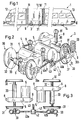
- the GTW 1 shown in FIG. 1 comprises a central drive unit 10 which on both sides via joints 11 with those provided for passenger transport Vehicle parts 12 and 13 (with running gear 14) is connected.
- the Drive unit 10 consists of a vehicle body 10 'and a drivable undercarriage 3, which has a suspension 9 with the vehicle body 10 'is connected and its wheels 31 are movable on rails 2.
- the undercarriage 3 of FIGS. 2 and 3 comprises two wheel sets 30, each can be driven via a motor 5 and a transmission 6.
- the wheel sets 30 are coupled via a pair of axle links 4, with which they automatically are radially adjustable with respect to a curve to be traversed.
- Each Axle linkage 4 comprises two rods 40a and 40b which are articulated over one short lever 41 are connected to each other and each corresponding pivot bearing housings 36a and 36b (Camp 37).
- the levers 41 of the two axle links 4 are around Coupling bearing 42 pivotally connected via a coupling shaft 43 can stand.
- the axle linkages 4 can the axle bearing housings 36a and 36b with the associated rods 40a and 40b can be rigidly connected.
- the motors 5 are each via the gear 6 and elastic elements, which comprise a hollow shaft 33, with the associated Wheelset 30 connected and on further elastic elements 81 am Vehicle body 10 'attached.
- the axle linkages 4 provide a frictional connection between Wheel axles 32 and the vehicle body 10 'forth, this frictional connection via elastic elements, namely elastically designed coupling bearings 42, to be led.
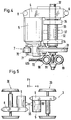
- FIG. 4 Another important component of a chassis 3, namely a brake 7, is shown in FIG. 4 (brake cylinder 70, lever 71 with brake shoes 72). She is fastened to the motor 5 and is therefore also related to the wheel set 30 cushioned. 4 is also the resilient connection between the Gear 6 and the wheel axle 32 shown. This is through the hollow shaft 33 and given two elastic connecting parts 34 and 35. Part 34 connects the hollow shaft 33 elastically to the wheel axle 32 while the part 35 an elastic connection between the hollow shaft 33 and the transmission 6 forms. Dash-dotted lines indicate a brake disk 37, which is an alternative can be provided for the brake 7. With such a disc brake the activatable components are attached to the vehicle body.
- Fig. 5 shows a chassis 3, the two motors 5 centrally via one Articulation point 55 are coupled such that for the coupled motors 5 a rotational pendulum movement (arrows 55 ') around a vertical central axis is possible in the z direction through the articulation point 55.
- Fig. 6 shows a chassis 3, the two motors 5 including the associated gear 6 are coupled at two points 56a and 56b, that a pendulum movement in the y direction (arrow 56 '), d. H. towards the Wheel axles 32, is possible.
- the motors 5 can be rigid via parallel pendulums be coupled so that the movements are only free in the y direction.
- the Coupling can also be soft, so that in addition to translational can also result in rotational pendulum movements.
- Another one Possibility is that the motors 5 are rigidly coupled in the x-y plane and are attached to the vehicle body 10 'via two parallel pendulums 8, wherein the pendulum rods 80 at both ends of spherical bearings 81 as Have connecting elements. In this case there are movements in the y direction and about the vertical central axis as in the embodiment of FIG Fig. 5 possible.
Landscapes
- Engineering & Computer Science (AREA)
- Mechanical Engineering (AREA)
- Chemical & Material Sciences (AREA)
- Combustion & Propulsion (AREA)
- Transportation (AREA)
- Arrangement Or Mounting Of Propulsion Units For Vehicles (AREA)
- Automatic Cycles, And Cycles In General (AREA)
- Platform Screen Doors And Railroad Systems (AREA)
Abstract
Description
- Fig. 1
- einen Gelenktriebwagen GTW mit einer erfindungsgemässen Antriebseinheit,
- Fig. 2
- eine schematische Darstellung eines Fahrwerks der Antriebseinheit,
- Fig. 3
- eine Draufsicht auf das Fahrwerk der Fig. 2,
- Fig. 4
- vereinfacht gezeichnete Details zum Fahrwerk der Fig. 2 und
- Fig. 5, 6
- Fahrwerke mit Motoren, die über Koppelelemente miteinander verbunden sind.
Claims (9)
- Antriebseinheit (10) zu einem Schienenfahrzeug (1), mit einem Fahrwerk (3), das rahmenlos einen Fahrzeugkasten (10') trägt, das zwei durch jeweils einen Motor (5) angetriebene Radsätze (30) umfasst und das über eine Federung (9) mit dem Fahrzeugkasten verbunden ist,
dadurch gekennzeichnet, dass die Motoren jeweils über ein Getriebe (6) und elastische Elemente, die eine Hohlwelle (32) umfassen, mit dem zugeordneten Radsatz verbunden sind und über weitere elastische Elemente (81) am Fahrzeugkasten befestigt sind. - Antriebseinheit nach Anspruch 1, dadurch gekennzeichnet, dass die Radsätze (30) über ein Paar von Achsanlenkungen (4) gekoppelt sind, mit denen sie selbsttätig radial bezüglich einer zu durchlaufenden Kurve einstellbar sind, wobei über jede Achsanlenkung ein Kraftschluss zwischen Radachsen (32) und dem Fahrzeugkasten (10') hergestellt ist und dieser Kraftschluss über elastische Elemente (42) geführt ist.
- Antriebseinheit nach Anspruch 2, dadurch gekennzeichnet, dass jede Achsanlenkung (4) zwei Stangen (40a, 40b) umfasst, die einerseits gelenkig über einen kurzen Hebel (41) miteinander verbunden sind sowie andererseits gelenkig oder starr mit Achslagergehäusen (36a, 36b) verbunden sind, und dass Koppellager (42), um welche die kurzen Hebel schwenkbar sind, elastisch ausgebildet sowie am Fahrzeugkasten (10') befestigt sind, wobei insbesondere die beiden Achsanlenkungen über eine zwischen den Koppellagern angeordnete Koppelwelle (43) verbunden sind.
- Antriebseinheit nach einem der Ansprüche 1 bis 3, dadurch gekennzeichnet, dass an den Motoren (5) jeweils eine Bremseinheit (7) für ein Rad (31) angeordnet ist.
- Antriebseinheit nach einem der Ansprüche 1 bis 3, dadurch gekennzeichnet, dass an den Hohlwellen (33) Bremsscheiben (37) angeordnet sind und dass zugeordnete Bremseinheiten mit aktivierbaren Teile der Bremse am Fahrzeugkasten (10') befestigt sind.
- Antriebseinheit nach einem der Ansprüche 1 bis 5, dadurch gekennzeichnet, dass die weiteren federnden Elemente zwischen Motoren (5) und Fahrzeugkasten (10') Pendelstangen (80) mit Sphärolagern (81) sind.
- Antriebseinheit nach einem der Ansprüche 1 bis 5, dadurch gekennzeichnet, dass die beiden Motoren (5) zentral über einen Anlenkpunkt (55) derart gekoppelt sind, dass für die gekoppelten Motoren eine rotatorische Pendelbewegung um eine vertikale Achse (z) durch den Anlenkpunkt möglich ist.
- Antriebseinheit nach einem der Ansprüche 1 bis 5, dadurch gekennzeichnet, dass die beiden Motoren (5) einschliesslich zugeordneter Getriebe (6) an zwei Stellen (56a, 56b) so gekoppelt sind, dass eine Pendelbewegung in Richtung (y) der Radachse (32) möglich ist.
- Schienenfahrzeug (1) mit einer Antriebseinheit (10) gemäss einem der Ansprüche 1 bis 8, dadurch gekennzeichnet, dass die Antriebseinheit (10) über Gelenke (11) zwischen zwei für einen Fahrgasttransport dienende Fahrzeugteilen (12, 13) angeordnet sind, die beide je auf einem Lauffahrwerk (14) gelagert sind.
Priority Applications (4)
| Application Number | Priority Date | Filing Date | Title |
|---|---|---|---|
| EP98810342A EP0952061B1 (de) | 1998-04-20 | 1998-04-20 | Antriebseinheit zu einem Schienenfahrzeug |
| AT98810342T ATE243129T1 (de) | 1998-04-20 | 1998-04-20 | Antriebseinheit zu einem schienenfahrzeug |
| ES98810342T ES2201427T3 (es) | 1998-04-20 | 1998-04-20 | Unidad motriz para un vehiculo ferroviario. |
| DE59808757T DE59808757D1 (de) | 1998-04-20 | 1998-04-20 | Antriebseinheit zu einem Schienenfahrzeug |
Applications Claiming Priority (1)
| Application Number | Priority Date | Filing Date | Title |
|---|---|---|---|
| EP98810342A EP0952061B1 (de) | 1998-04-20 | 1998-04-20 | Antriebseinheit zu einem Schienenfahrzeug |
Publications (2)
| Publication Number | Publication Date |
|---|---|
| EP0952061A1 true EP0952061A1 (de) | 1999-10-27 |
| EP0952061B1 EP0952061B1 (de) | 2003-06-18 |
Family
ID=8236044
Family Applications (1)
| Application Number | Title | Priority Date | Filing Date |
|---|---|---|---|
| EP98810342A Expired - Lifetime EP0952061B1 (de) | 1998-04-20 | 1998-04-20 | Antriebseinheit zu einem Schienenfahrzeug |
Country Status (4)
| Country | Link |
|---|---|
| EP (1) | EP0952061B1 (de) |
| AT (1) | ATE243129T1 (de) |
| DE (1) | DE59808757D1 (de) |
| ES (1) | ES2201427T3 (de) |
Cited By (3)
| Publication number | Priority date | Publication date | Assignee | Title |
|---|---|---|---|---|
| EP1209057A1 (de) * | 2000-11-17 | 2002-05-29 | Siemens Aktiengesellschaft | Triebfahrzeug mit zumindest einem Drehgestell |
| JP2016215684A (ja) * | 2015-05-14 | 2016-12-22 | 新日鐵住金株式会社 | 鉄道車両 |
| CN106740897A (zh) * | 2016-12-09 | 2017-05-31 | 中车株洲电力机车有限公司 | 高速轨道车辆及其转向架、轮对驱动装置 |
Families Citing this family (1)
| Publication number | Priority date | Publication date | Assignee | Title |
|---|---|---|---|---|
| AT524028B1 (de) * | 2020-09-29 | 2022-02-15 | Siemens Mobility Austria Gmbh | Fahrwerk für ein Schienenfahrzeug |
Citations (7)
| Publication number | Priority date | Publication date | Assignee | Title |
|---|---|---|---|---|
| CH246410A (de) * | 1945-01-27 | 1946-12-31 | Schweizerische Lokomotiv | Schienenfahrzeuguntergestell mit Elektromotor mit Nasenaufhängung. |
| DE963339C (de) * | 1952-07-29 | 1957-05-09 | Siemens Schuckertwerke Ges M B | Rahmenloses Triebdrehgestell fuer Schienenfahrzeuge |
| EP0025409A2 (de) * | 1979-09-07 | 1981-03-18 | Siemens Aktiengesellschaft | Schienengebundenes elektrisches Triebfahrzeug |
| EP0534899A1 (de) | 1991-09-26 | 1993-03-31 | SLM Schweizerische Lokomotiv- und Maschinenfabrik AG | Antrieb für einen Radsatz eines Schienentriebfahrzeuges und Federelement für einen derartigen Antrieb |
| EP0542174A1 (de) * | 1991-11-13 | 1993-05-19 | ABBPATENT GmbH | Schienentriebfahrzeug |
| EP0649782A1 (de) | 1993-10-21 | 1995-04-26 | SLM Schweizerische Lokomotiv- und Maschinenfabrik AG | Schienenfahrzeug und Fahrwerk für ein derartiges Fahrzeug |
| DE4419878C1 (de) * | 1994-06-07 | 1995-07-20 | Sig Schweiz Industrieges | In axialer Richtung bewegliche Achsanordnung für Schienenfahrzeuge |
-
1998
- 1998-04-20 AT AT98810342T patent/ATE243129T1/de active
- 1998-04-20 ES ES98810342T patent/ES2201427T3/es not_active Expired - Lifetime
- 1998-04-20 DE DE59808757T patent/DE59808757D1/de not_active Expired - Lifetime
- 1998-04-20 EP EP98810342A patent/EP0952061B1/de not_active Expired - Lifetime
Patent Citations (7)
| Publication number | Priority date | Publication date | Assignee | Title |
|---|---|---|---|---|
| CH246410A (de) * | 1945-01-27 | 1946-12-31 | Schweizerische Lokomotiv | Schienenfahrzeuguntergestell mit Elektromotor mit Nasenaufhängung. |
| DE963339C (de) * | 1952-07-29 | 1957-05-09 | Siemens Schuckertwerke Ges M B | Rahmenloses Triebdrehgestell fuer Schienenfahrzeuge |
| EP0025409A2 (de) * | 1979-09-07 | 1981-03-18 | Siemens Aktiengesellschaft | Schienengebundenes elektrisches Triebfahrzeug |
| EP0534899A1 (de) | 1991-09-26 | 1993-03-31 | SLM Schweizerische Lokomotiv- und Maschinenfabrik AG | Antrieb für einen Radsatz eines Schienentriebfahrzeuges und Federelement für einen derartigen Antrieb |
| EP0542174A1 (de) * | 1991-11-13 | 1993-05-19 | ABBPATENT GmbH | Schienentriebfahrzeug |
| EP0649782A1 (de) | 1993-10-21 | 1995-04-26 | SLM Schweizerische Lokomotiv- und Maschinenfabrik AG | Schienenfahrzeug und Fahrwerk für ein derartiges Fahrzeug |
| DE4419878C1 (de) * | 1994-06-07 | 1995-07-20 | Sig Schweiz Industrieges | In axialer Richtung bewegliche Achsanordnung für Schienenfahrzeuge |
Cited By (4)
| Publication number | Priority date | Publication date | Assignee | Title |
|---|---|---|---|---|
| EP1209057A1 (de) * | 2000-11-17 | 2002-05-29 | Siemens Aktiengesellschaft | Triebfahrzeug mit zumindest einem Drehgestell |
| JP2016215684A (ja) * | 2015-05-14 | 2016-12-22 | 新日鐵住金株式会社 | 鉄道車両 |
| CN106740897A (zh) * | 2016-12-09 | 2017-05-31 | 中车株洲电力机车有限公司 | 高速轨道车辆及其转向架、轮对驱动装置 |
| CN106740897B (zh) * | 2016-12-09 | 2019-02-26 | 中车株洲电力机车有限公司 | 高速轨道车辆及其转向架、轮对驱动装置 |
Also Published As
| Publication number | Publication date |
|---|---|
| ES2201427T3 (es) | 2004-03-16 |
| ATE243129T1 (de) | 2003-07-15 |
| EP0952061B1 (de) | 2003-06-18 |
| DE59808757D1 (de) | 2003-07-24 |
Similar Documents
| Publication | Publication Date | Title |
|---|---|---|
| EP0770013B1 (de) | Angetriebenes laufwerk für schienenfahrzeuge mit spurwechseleinrichtung | |
| DE69425390T2 (de) | Schienenfahrzeugaufhängung | |
| EP0589864B1 (de) | Triebfahrzeug, insbesondere Eisenbahn-Triebfahrzeug | |
| DE19506888C2 (de) | Antriebseinheit für elektrische Schienenfahrzeuge | |
| DE3130603A1 (de) | Triebdrehgestell fuer ein schienenfahrzeug | |
| DE4143519C2 (de) | Vorrichtung zur Übertragung von Traktionskräften in Drehgestellen von Schienenfahrzeugen | |
| EP0848676B1 (de) | Drehgestell für schienenfahrzeuge | |
| EP0649782B1 (de) | Schienenfahrzeug und Fahrwerk für ein derartiges Fahrzeug | |
| DE60017067T2 (de) | Triebdrehgestell für ein Schienenfahrzeug und Schienenfahrzeug mit solch einem Drehgestell | |
| EP0952061B1 (de) | Antriebseinheit zu einem Schienenfahrzeug | |
| DE69312803T2 (de) | Drehgestell für ein Schienenfahrzeug mit am Rahmen aufgehängten Direktmotoren und Getrieben | |
| EP0308720B1 (de) | Angetriebenes Einzelrad-Fahrwerk für Niederflur-Stadtbahnwagen unterschiedlicher Spurweite | |
| DE2910392A1 (de) | Drehgestell fuer schienenfahrzeuge, insbesondere fuer strassenbahnen o.dgl. | |
| EP0568044B1 (de) | Laufwerk für ein Schienenfahrzeug | |
| EP1532033B1 (de) | Triebgestell für ein schienenfahrzeug | |
| AT407980B (de) | Laufwerk für schienenfahrzeuge | |
| DE69929675T2 (de) | Triebdrehgestell eines zugfahrzeuges | |
| EP0930210B1 (de) | Fahrwerk für Schienenfahrzeuge und Schienenfahrzeug mit mindestens einem derartigen Fahrwerk | |
| WO2014131688A1 (de) | Motorfahrwerk für schienenfahrzeuge | |
| EP0290782A1 (de) | Drehgestell für Schienenfahrzeuge, insbesondere für Stadtbahnwagen | |
| EP0782519B1 (de) | Einrichtung zur abstützung, führung und lenkung eines gebremsten und/oder angetriebenen radsatzes für schienenfahrzeuge | |
| EP0444017B1 (de) | Radsatzsteuerung für Drehgestelle von Schienenfahrzeugen | |
| DE3232939C2 (de) | Abstützvorrichtung für Drehmomentstützen von Achsgetriebegehäusen bei Schienentriebfahrzeugen | |
| DE1455165C (de) | Mehrachsiges Schienentriebfahrzeug | |
| AT401034B (de) | Fahrwerk, insbesondere drehgestell, für ein schienenfahrzeug |
Legal Events
| Date | Code | Title | Description |
|---|---|---|---|
| PUAI | Public reference made under article 153(3) epc to a published international application that has entered the european phase |
Free format text: ORIGINAL CODE: 0009012 |
|
| AK | Designated contracting states |
Kind code of ref document: A1 Designated state(s): AT CH DE ES FR GB GR IT LI SE |
|
| AX | Request for extension of the european patent |
Free format text: AL;LT;LV;MK;RO;SI |
|
| RAP1 | Party data changed (applicant data changed or rights of an application transferred) |
Owner name: DAIMLERCHRYSLER AG |
|
| 17P | Request for examination filed |
Effective date: 20000317 |
|
| AKX | Designation fees paid |
Free format text: AT CH DE ES FR GB GR IT LI SE |
|
| RAP1 | Party data changed (applicant data changed or rights of an application transferred) |
Owner name: DAIMLERCHRYSLER RAIL SYSTEMS GMBH |
|
| GRAH | Despatch of communication of intention to grant a patent |
Free format text: ORIGINAL CODE: EPIDOS IGRA |
|
| GRAH | Despatch of communication of intention to grant a patent |
Free format text: ORIGINAL CODE: EPIDOS IGRA |
|
| RAP1 | Party data changed (applicant data changed or rights of an application transferred) |
Owner name: BOMBARDIER TRANSPORTATION GMBH |
|
| GRAA | (expected) grant |
Free format text: ORIGINAL CODE: 0009210 |
|
| AK | Designated contracting states |
Designated state(s): AT CH DE ES FR GB GR IT LI SE |
|
| REG | Reference to a national code |
Ref country code: GB Ref legal event code: FG4D Free format text: NOT ENGLISH |
|
| REG | Reference to a national code |
Ref country code: CH Ref legal event code: EP |
|
| GBT | Gb: translation of ep patent filed (gb section 77(6)(a)/1977) | ||
| REF | Corresponds to: |
Ref document number: 59808757 Country of ref document: DE Date of ref document: 20030724 Kind code of ref document: P |
|
| REG | Reference to a national code |
Ref country code: GR Ref legal event code: EP Ref document number: 20030403374 Country of ref document: GR |
|
| REG | Reference to a national code |
Ref country code: SE Ref legal event code: TRGR |
|
| ET | Fr: translation filed | ||
| REG | Reference to a national code |
Ref country code: ES Ref legal event code: FG2A Ref document number: 2201427 Country of ref document: ES Kind code of ref document: T3 |
|
| PLBE | No opposition filed within time limit |
Free format text: ORIGINAL CODE: 0009261 |
|
| STAA | Information on the status of an ep patent application or granted ep patent |
Free format text: STATUS: NO OPPOSITION FILED WITHIN TIME LIMIT |
|
| 26N | No opposition filed |
Effective date: 20040319 |
|
| PGFP | Annual fee paid to national office [announced via postgrant information from national office to epo] |
Ref country code: ES Payment date: 20110426 Year of fee payment: 14 Ref country code: FR Payment date: 20110510 Year of fee payment: 14 Ref country code: GR Payment date: 20110418 Year of fee payment: 14 Ref country code: SE Payment date: 20110414 Year of fee payment: 14 Ref country code: CH Payment date: 20110428 Year of fee payment: 14 Ref country code: DE Payment date: 20110421 Year of fee payment: 14 |
|
| PGFP | Annual fee paid to national office [announced via postgrant information from national office to epo] |
Ref country code: GB Payment date: 20110421 Year of fee payment: 14 Ref country code: AT Payment date: 20110414 Year of fee payment: 14 |
|
| PGFP | Annual fee paid to national office [announced via postgrant information from national office to epo] |
Ref country code: IT Payment date: 20110422 Year of fee payment: 14 |
|
| REG | Reference to a national code |
Ref country code: CH Ref legal event code: PL |
|
| REG | Reference to a national code |
Ref country code: SE Ref legal event code: EUG |
|
| REG | Reference to a national code |
Ref country code: AT Ref legal event code: MM01 Ref document number: 243129 Country of ref document: AT Kind code of ref document: T Effective date: 20120420 |
|
| GBPC | Gb: european patent ceased through non-payment of renewal fee |
Effective date: 20120420 |
|
| REG | Reference to a national code |
Ref country code: FR Ref legal event code: ST Effective date: 20121228 |
|
| REG | Reference to a national code |
Ref country code: GR Ref legal event code: ML Ref document number: 20030403374 Country of ref document: GR Effective date: 20121102 |
|
| PG25 | Lapsed in a contracting state [announced via postgrant information from national office to epo] |
Ref country code: GB Free format text: LAPSE BECAUSE OF NON-PAYMENT OF DUE FEES Effective date: 20120420 Ref country code: LI Free format text: LAPSE BECAUSE OF NON-PAYMENT OF DUE FEES Effective date: 20120430 Ref country code: AT Free format text: LAPSE BECAUSE OF NON-PAYMENT OF DUE FEES Effective date: 20120420 Ref country code: CH Free format text: LAPSE BECAUSE OF NON-PAYMENT OF DUE FEES Effective date: 20120430 |
|
| REG | Reference to a national code |
Ref country code: DE Ref legal event code: R119 Ref document number: 59808757 Country of ref document: DE Effective date: 20121101 |
|
| PG25 | Lapsed in a contracting state [announced via postgrant information from national office to epo] |
Ref country code: IT Free format text: LAPSE BECAUSE OF NON-PAYMENT OF DUE FEES Effective date: 20120420 Ref country code: FR Free format text: LAPSE BECAUSE OF NON-PAYMENT OF DUE FEES Effective date: 20120430 Ref country code: SE Free format text: LAPSE BECAUSE OF NON-PAYMENT OF DUE FEES Effective date: 20120421 Ref country code: GR Free format text: LAPSE BECAUSE OF NON-PAYMENT OF DUE FEES Effective date: 20121102 |
|
| REG | Reference to a national code |
Ref country code: ES Ref legal event code: FD2A Effective date: 20130716 |
|
| PG25 | Lapsed in a contracting state [announced via postgrant information from national office to epo] |
Ref country code: ES Free format text: LAPSE BECAUSE OF NON-PAYMENT OF DUE FEES Effective date: 20120421 |
|
| PG25 | Lapsed in a contracting state [announced via postgrant information from national office to epo] |
Ref country code: DE Free format text: LAPSE BECAUSE OF NON-PAYMENT OF DUE FEES Effective date: 20121101 |