EP0952523A1 - Unité fonctionnelle pour une commande programmable par mémoire avec une fonction de redondance - Google Patents
Unité fonctionnelle pour une commande programmable par mémoire avec une fonction de redondance Download PDFInfo
- Publication number
- EP0952523A1 EP0952523A1 EP98107284A EP98107284A EP0952523A1 EP 0952523 A1 EP0952523 A1 EP 0952523A1 EP 98107284 A EP98107284 A EP 98107284A EP 98107284 A EP98107284 A EP 98107284A EP 0952523 A1 EP0952523 A1 EP 0952523A1
- Authority
- EP
- European Patent Office
- Prior art keywords
- functional unit
- slot
- bus
- functional
- unit according
- Prior art date
- Legal status (The legal status is an assumption and is not a legal conclusion. Google has not performed a legal analysis and makes no representation as to the accuracy of the status listed.)
- Granted
Links
Images


Classifications
-
- G—PHYSICS
- G05—CONTROLLING; REGULATING
- G05B—CONTROL OR REGULATING SYSTEMS IN GENERAL; FUNCTIONAL ELEMENTS OF SUCH SYSTEMS; MONITORING OR TESTING ARRANGEMENTS FOR SUCH SYSTEMS OR ELEMENTS
- G05B19/00—Program-control systems
- G05B19/02—Program-control systems electric
- G05B19/04—Program control other than numerical control, i.e. in sequence controllers or logic controllers
- G05B19/05—Programmable logic controllers, e.g. simulating logic interconnections of signals according to ladder diagrams or function charts
- G05B19/054—Input/output
-
- G—PHYSICS
- G05—CONTROLLING; REGULATING
- G05B—CONTROL OR REGULATING SYSTEMS IN GENERAL; FUNCTIONAL ELEMENTS OF SUCH SYSTEMS; MONITORING OR TESTING ARRANGEMENTS FOR SUCH SYSTEMS OR ELEMENTS
- G05B2219/00—Program-control systems
- G05B2219/10—Plc systems
- G05B2219/11—Plc I-O input output
- G05B2219/1197—Each interface, module has simulation module which takes over control
-
- G—PHYSICS
- G05—CONTROLLING; REGULATING
- G05B—CONTROL OR REGULATING SYSTEMS IN GENERAL; FUNCTIONAL ELEMENTS OF SUCH SYSTEMS; MONITORING OR TESTING ARRANGEMENTS FOR SUCH SYSTEMS OR ELEMENTS
- G05B2219/00—Program-control systems
- G05B2219/10—Plc systems
- G05B2219/15—Plc structure of the system
- G05B2219/15008—Identify connected I-O and store in address table
-
- G—PHYSICS
- G05—CONTROLLING; REGULATING
- G05B—CONTROL OR REGULATING SYSTEMS IN GENERAL; FUNCTIONAL ELEMENTS OF SUCH SYSTEMS; MONITORING OR TESTING ARRANGEMENTS FOR SUCH SYSTEMS OR ELEMENTS
- G05B2219/00—Program-control systems
- G05B2219/10—Plc systems
- G05B2219/15—Plc structure of the system
- G05B2219/15013—Set configuration, address of connected module from fixed non volatile
Definitions
- the invention relates to a plug-in functional unit for a programmable logic controller according to the preamble of claim 1 and a programmable logic controller according to claim 8.
- programmable logic controllers with plug-in functional units are known, in which the bus system of the controllers comprises a system bus, as well as an address bus with associated selection lines and a control bus.
- a selection line leads to the pluggable functional units and is connected to one of the lines of the address bus.
- the assigned CPU can output signals via the control bus which cause the functional units to signal to the CPU on the selection lines which lead to the address bus that these are plugged into a specific slot.
- the signaling takes place via a collecting line and the feedback via exactly the selection line that is assigned to this slot.
- the slot in which a functional unit is inserted can be precisely recognized by the assigned CPU, but the respective functional unit has only a single selection connection and the conventional functional unit cannot recognize where it is inserted.
- this can be a major disadvantage in certain cases. If, for example, an inserted functional unit has a defect, the area of resources assigned to this functional unit may be completely unusable under certain circumstances. This means that downstream devices connected to the functional unit are no longer addressed and the memory area occupied by the functional unit and assigned to the slot is no longer available.
- conventional systems depending on their programming, generate an error message or interrupt the current operating state of the programmable logic controller. The execution of the running program can be delayed until the faulty functional unit is replaced or repaired, or under certain circumstances even stopped entirely.
- the invention is therefore based on the object of alleviating the restrictions of conventional programmable logic systems with regard to the signaling of an occupied state and also to allow a more flexible use of the resources assigned to the respective functional units.
- the invention no longer requires the conventional selection lines, which are each routed to an address line assigned to the pluggable functional unit, but instead the address bus, which is also referred to below as the peripheral selection bus, is accessed without signaling on the selection line, and it is replaced by the Functional unit according to the invention on the address bus only some slot is displayed as occupied, in which no other active functional unit is inserted. As a result, any free memory locations can be displayed as occupied and their resources freely available. Is For example, if a slot is faulty, the functional unit according to the invention can use the resources of this slot from another slot that is actually occupied by this slot.
- the functional unit according to the invention can use the resources, i.e. use the address spaces or input / output areas assigned to a slot or use several free slots for themselves and display them as occupied and thereby achieve a significantly higher data throughput.
- the storage means of the functional unit store the numbers of more than one slot and indicate the occupancy of these slots by the functional unit on the address bus.
- the assignment of the slots can be signaled dynamically from the plug-in functional unit itself. Since very high data throughputs can occur in today's systems, for example with lightwave communication devices, much higher amounts of data can be transmitted in such applications with the functional unit according to the invention than was previously possible at all. As a result, a multiple of peripheral devices can be connected or additional data can be transmitted for the control of these devices.
- the occupancy status of the slots can be coordinated with one another and a dynamic assignment of the slots and their Resources are made.
- plug-in functional units can be provided externally, in a manner well known to the person skilled in the art, with corresponding multiple connections to peripheral devices, so that the emulation of the faulty plug-in functional unit does not lead to a functional failure of the peripheral devices.
- the failure of a conventional functional unit can also be recognized by the lack of its signaling of the slot assignment and the conventional functional unit can also be emulated.
- a desired and an actual state of the assignment with inserted functional units is advantageously stored in the memory device of the functional unit according to the invention, this can be compared by means of a comparator device and a control signal can be generated if the actual state deviates from the desired state. Since this control signal represents the failure of the functional units recognized as missing, their immediate emulation can be carried out on the basis of this signal by a functional unit according to the invention which was determined beforehand for this purpose.
- the functional unit according to the invention has a signaling line, by means of which the deviation of the actual state from the target state is reported and recognized by the assigned CPU.
- the CPU can indicate the faulty operation on assigned display devices and the defective functional unit can even be removed from the system without peripheral modules or devices having come to a standstill and subsequently replaced by an intact functional unit.
- Detection of the replacement by the pluggable functional unit according to the invention ends the emulation of the failed pluggable functional unit.
- FIG. 1 represents a functional unit according to the invention, generally designated 1.
- the functional unit 1 comprises connection means 2, shown as dark squares, which establish a connection between the unit 1 and the bus system 3 of the programmable logic controller.
- the bus system 3 comprises a system bus 4 with a data bus and a memory address bus for process data exchange between the assigned CPU and the pluggable functional units, and comprises a control bus 5 and an address bus 6, also called peripheral selection bus.
- a selection line 7 leads to a predefined connection location, which is the same for all slots, at which the conventional plug-in functional units signal their busy signal to the address bus 6.
- the selection lines 7 are not accessed and there are no associated connections.
- the functional unit 1 comprises storage means 8, 9, preferably in the form of a register, in which the address of a free slot or a slot in which a non-active functional unit is inserted is stored.
- the functional unit 1 If the request to indicate the slot of the CPU to the CPU is signaled via a bus of the control bus 5, the functional unit 1 outputs the slot whose resources are used directly to the address bus 6.
- the address of this slot does not have to match the slot that is actually plugged in, and in a further embodiment according to the invention, the addresses of several slots are output on the address bus 6 by a single functional unit 1 on request from the CPU. In the latter case, the associated resources of all slot addresses output, such as their usable memory areas as well Input / output areas used by a single functional unit according to the invention.
- These addresses can be supplied to the functional unit 1 via the system bus 4, controlled by an associated user software, or, in an alternative embodiment, can be set on the functional unit 1 itself using DIP switches (not shown in the drawings).
- register 9 comprises a bit-mapped representation of slots occupied by active other functional units and of remaining, i.e. to use free slots.
- This bit mask can also include further functional units which are emulated by the functional unit 1 according to the invention if they fail.
- the actual assignment of the programmable logic controller with functional units is stored in register 8 and compared by comparator 10 with the target state stored in register 9. If there is a discrepancy between the target and the actual state, the comparator 10 can inform an interface unit 11, which generates a message signal on the line 12, which notifies the assigned CPU of the incorrect assignment.
- this incorrect assignment is transmitted to external or other functional units according to the invention on a configuration channel 13.
- the functional unit 1 can also be given the bit-mapped value for the register 9 from other data sources.
- the recognized actual state can be communicated with one another directly via the configuration channel, or it can Functional units according to the invention perform a dynamic assignment of slots to one another via the configuration channel 13.
- a functional unit 1 can also include the functionality of a different unit in assigned memory means, not shown in the figures file to emulate these units if necessary.
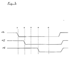
- the time behavior occurring during operation is shown as an example in FIG. 3.
- Reference number 14 denotes the signal on the line of the control bus 5 which instructs the functional units to output their busy signal on their selection lines 7.
- Reference symbol 15 represents the signal curve of a conventional functional unit, as occurs on one of the selection lines 7.
- Reference numeral 16 represents the signal curve of a functional unit according to the invention directly on the address bus 6.
- the timing of the signals is as follows. An assigned CPU queries the system equipment by activating the control signal at time t 1 . The functional units present at time t 2 then signal their presence on the associated selection line 7.
- the functional unit 1 can likewise output the occupied signal of the slots it manages directly to the address bus 6 at time t 2 or can first check whether the occupied signals of all functional units to be emulated by it are present and is read after the actual Start the state with the comparison operation.
- the signal of all slots to be managed by the functional unit 1 according to the invention is output at time t 4 and recognized by the assigned CPU at time t 5 .
- the times t 3 and t 4 are always selected by correspondingly fast functional units so that they are before the time t 5 , and in this way secure signaling of the respective occupied state is achieved. This means that the emulation also occurs before time t 5 failed functional units started and a system downtime avoided.
Landscapes
- Physics & Mathematics (AREA)
- General Physics & Mathematics (AREA)
- Engineering & Computer Science (AREA)
- Automation & Control Theory (AREA)
- Programmable Controllers (AREA)
- Debugging And Monitoring (AREA)
Priority Applications (4)
| Application Number | Priority Date | Filing Date | Title |
|---|---|---|---|
| DE59811718T DE59811718D1 (de) | 1998-04-22 | 1998-04-22 | Funktionseinheit für eine speicherprogrammierbare Steuerung mit Redundanzfunktion |
| DE29807417U DE29807417U1 (de) | 1998-04-22 | 1998-04-22 | Funktionseinheit für eine speicherprogrammierbare Steuerung mit Redundanzfunktion |
| ES98107284T ES2221092T3 (es) | 1998-04-22 | 1998-04-22 | Unidad funcional para un control programable con memoria de funcion de redundancia. |
| EP19980107284 EP0952523B1 (fr) | 1998-04-22 | 1998-04-22 | Unité fonctionnelle pour une commande programmable par mémoire avec une fonction de redondance |
Applications Claiming Priority (1)
| Application Number | Priority Date | Filing Date | Title |
|---|---|---|---|
| EP19980107284 EP0952523B1 (fr) | 1998-04-22 | 1998-04-22 | Unité fonctionnelle pour une commande programmable par mémoire avec une fonction de redondance |
Publications (2)
| Publication Number | Publication Date |
|---|---|
| EP0952523A1 true EP0952523A1 (fr) | 1999-10-27 |
| EP0952523B1 EP0952523B1 (fr) | 2004-07-28 |
Family
ID=8231796
Family Applications (1)
| Application Number | Title | Priority Date | Filing Date |
|---|---|---|---|
| EP19980107284 Expired - Lifetime EP0952523B1 (fr) | 1998-04-22 | 1998-04-22 | Unité fonctionnelle pour une commande programmable par mémoire avec une fonction de redondance |
Country Status (3)
| Country | Link |
|---|---|
| EP (1) | EP0952523B1 (fr) |
| DE (2) | DE29807417U1 (fr) |
| ES (1) | ES2221092T3 (fr) |
Cited By (4)
| Publication number | Priority date | Publication date | Assignee | Title |
|---|---|---|---|---|
| EP2042952A1 (fr) * | 2007-09-26 | 2009-04-01 | Siemens Aktiengesellschaft | Commande d'appareil de commutation, appareil de commutation et procédé de commande d'un appareil de commutation |
| CN103197586A (zh) * | 2013-04-11 | 2013-07-10 | 南京盘谷电气科技有限公司 | 一种基于微处理器的配网终端自动识别技术 |
| EP2568788A3 (fr) * | 2011-09-08 | 2014-09-03 | Schneider Electric Industries SAS | Dispositif et procédé de contrôle d'appareil ou d'installation électrique, installation électrique comportant un tel dispositif |
| LU101427B1 (de) | 2019-10-02 | 2021-04-08 | Phoenix Contact Gmbh & Co | Ein/Ausgabe-Station für ein Feldbussystem, Feldbus-Koppler für die Ein/Ausgabe-Station, sowie Platzhaltermodul für die Ein/Ausgabe-Station |
Citations (3)
| Publication number | Priority date | Publication date | Assignee | Title |
|---|---|---|---|---|
| US4188670A (en) * | 1978-01-11 | 1980-02-12 | Mcdonnell Douglas Corporation | Associative interconnection circuit |
| GB2202062A (en) * | 1987-03-14 | 1988-09-14 | Plessey Co Plc | Checking a system configuration |
| EP0674786B1 (fr) * | 1992-12-21 | 1997-03-19 | Siemens Aktiengesellschaft | Dispositif a unites fonctionnelles enfichables |
-
1998
- 1998-04-22 DE DE29807417U patent/DE29807417U1/de not_active Expired - Lifetime
- 1998-04-22 EP EP19980107284 patent/EP0952523B1/fr not_active Expired - Lifetime
- 1998-04-22 DE DE59811718T patent/DE59811718D1/de not_active Expired - Lifetime
- 1998-04-22 ES ES98107284T patent/ES2221092T3/es not_active Expired - Lifetime
Patent Citations (3)
| Publication number | Priority date | Publication date | Assignee | Title |
|---|---|---|---|---|
| US4188670A (en) * | 1978-01-11 | 1980-02-12 | Mcdonnell Douglas Corporation | Associative interconnection circuit |
| GB2202062A (en) * | 1987-03-14 | 1988-09-14 | Plessey Co Plc | Checking a system configuration |
| EP0674786B1 (fr) * | 1992-12-21 | 1997-03-19 | Siemens Aktiengesellschaft | Dispositif a unites fonctionnelles enfichables |
Non-Patent Citations (1)
| Title |
|---|
| BUDZINSKI: "Geographic addressing with Multibus II", NEW ELECTRONICS., vol. 19, no. 14, July 1986 (1986-07-01), LONDON GB, pages 27 - 28, XP000211799 * |
Cited By (6)
| Publication number | Priority date | Publication date | Assignee | Title |
|---|---|---|---|---|
| EP2042952A1 (fr) * | 2007-09-26 | 2009-04-01 | Siemens Aktiengesellschaft | Commande d'appareil de commutation, appareil de commutation et procédé de commande d'un appareil de commutation |
| EP2568788A3 (fr) * | 2011-09-08 | 2014-09-03 | Schneider Electric Industries SAS | Dispositif et procédé de contrôle d'appareil ou d'installation électrique, installation électrique comportant un tel dispositif |
| CN103197586A (zh) * | 2013-04-11 | 2013-07-10 | 南京盘谷电气科技有限公司 | 一种基于微处理器的配网终端自动识别技术 |
| LU101427B1 (de) | 2019-10-02 | 2021-04-08 | Phoenix Contact Gmbh & Co | Ein/Ausgabe-Station für ein Feldbussystem, Feldbus-Koppler für die Ein/Ausgabe-Station, sowie Platzhaltermodul für die Ein/Ausgabe-Station |
| WO2021064004A1 (fr) | 2019-10-02 | 2021-04-08 | Phoenix Contact Gmbh & Co. Kg | Station d'entrée/sortie pour un système de bus de terrain, coupleur de bus de terrain pour la station d'entrée/sortie et module d'espace réservé pour la station d'entrée/sortie |
| US11868289B2 (en) | 2019-10-02 | 2024-01-09 | Phoenix Contact Gmbh & Co. Kg | Input/output station for a field bus system, field bus coupler for the input/output station, and placeholder module for the input/output station |
Also Published As
| Publication number | Publication date |
|---|---|
| DE29807417U1 (de) | 1999-09-02 |
| DE59811718D1 (de) | 2004-09-02 |
| EP0952523B1 (fr) | 2004-07-28 |
| ES2221092T3 (es) | 2004-12-16 |
Similar Documents
| Publication | Publication Date | Title |
|---|---|---|
| DE3486130T2 (de) | Uebertragungsleitungssteuerung. | |
| DE19927635B4 (de) | Sicherheitsbezogenes Automatisierungsbussystem | |
| DE69615611T2 (de) | Externes Speichersystem mit redundanten Speichersteuerungen | |
| DE68926436T2 (de) | Plattenlaufwerkanordnungssystem und Verfahren | |
| DE2829550C2 (fr) | ||
| DE3429941C2 (de) | Kommunikationssystem für Fahrzeugkörper | |
| EP1346881A2 (fr) | Méthode et dispositif de réception de données | |
| EP1639465B1 (fr) | Procede permettant de surveiller l'execution d'un programme dans un micro-ordinateur | |
| EP2491492B1 (fr) | Système d'automatisation et procédé pour faire fonctionner un système d'automatisation | |
| EP0952523B1 (fr) | Unité fonctionnelle pour une commande programmable par mémoire avec une fonction de redondance | |
| EP1000810B1 (fr) | Système d'ordinateur pour véhicule | |
| EP2480940A1 (fr) | Procédé de mise à disposition de fonctions de sécurité | |
| DE3238826A1 (de) | Steuereinheit fuer die eingabe/ausgabe-interface-schaltungen eines rechners | |
| EP1197418A1 (fr) | Pocédé de commande pour un processus à sécurité critique dans le service ferroviaire et dispositif pour mettre en oeuvre ce procédé | |
| DE69636805T2 (de) | Massenspeicherplattenanordnung zur Verwendung in Rechnersystemen | |
| EP0358785B1 (fr) | Dispositif pour la mise en fonctionnement d'un système multiprocesseur répondant destiné à la commande d'une cabine à signaux électronique dans la technique des signaux de chemin de fer | |
| EP2090947B1 (fr) | Procédé destiné au réglage d'adresses d'appareils de terrain | |
| DE2034423C3 (de) | Verfahren zur Fehlersuche in einem programmgesteuerten Vermittlungssystem | |
| DE102006035890A1 (de) | System und Verfahren zur automatischen Installation und Wartung von Hard- und Software in einem verteilten Computersystem | |
| EP0562353A2 (fr) | Méthode pour transférer des programmes et données de haute priorité dans un système de communications | |
| DE69630326T2 (de) | Informationsspeicherungssteuerungsgerät | |
| DE69433155T2 (de) | Programmierbare Matrize zum Prüfen von Fehlern in einem digitalen Kommunikationssystem | |
| DE69829909T2 (de) | Wahlverfahren von der aktiven Station in einem gesicherten System für Informationsverarbeitung | |
| EP0961973B1 (fr) | Appareil electronique redondant a canaux certifies et non certifies avec methode correspondante | |
| WO1997022057A1 (fr) | Procede de reglage d'adresses dans des systemes de bus a cablage parallele, et dispositif pour la mise en oeuvre de ce procede |
Legal Events
| Date | Code | Title | Description |
|---|---|---|---|
| PUAI | Public reference made under article 153(3) epc to a published international application that has entered the european phase |
Free format text: ORIGINAL CODE: 0009012 |
|
| AK | Designated contracting states |
Kind code of ref document: A1 Designated state(s): BE DE ES FR GB IT NL |
|
| AX | Request for extension of the european patent |
Free format text: AL;LT;LV;MK;RO;SI |
|
| RTI1 | Title (correction) |
Free format text: FUNCTIONAL UNIT FOR A PROGRAMMABLE CONTROLLER HAVING REDUNDANCY FUNCTION |
|
| 17P | Request for examination filed |
Effective date: 20000422 |
|
| AKX | Designation fees paid |
Free format text: BE DE ES FR GB IT NL |
|
| RAP1 | Party data changed (applicant data changed or rights of an application transferred) |
Owner name: PHOENIX CONTACT GMBH & CO. KG |
|
| GRAP | Despatch of communication of intention to grant a patent |
Free format text: ORIGINAL CODE: EPIDOSNIGR1 |
|
| GRAS | Grant fee paid |
Free format text: ORIGINAL CODE: EPIDOSNIGR3 |
|
| GRAA | (expected) grant |
Free format text: ORIGINAL CODE: 0009210 |
|
| AK | Designated contracting states |
Kind code of ref document: B1 Designated state(s): BE DE ES FR GB IT NL |
|
| REG | Reference to a national code |
Ref country code: GB Ref legal event code: FG4D Free format text: NOT ENGLISH |
|
| GBT | Gb: translation of ep patent filed (gb section 77(6)(a)/1977) |
Effective date: 20040728 |
|
| REF | Corresponds to: |
Ref document number: 59811718 Country of ref document: DE Date of ref document: 20040902 Kind code of ref document: P |
|
| REG | Reference to a national code |
Ref country code: ES Ref legal event code: FG2A Ref document number: 2221092 Country of ref document: ES Kind code of ref document: T3 |
|
| ET | Fr: translation filed | ||
| PLBE | No opposition filed within time limit |
Free format text: ORIGINAL CODE: 0009261 |
|
| STAA | Information on the status of an ep patent application or granted ep patent |
Free format text: STATUS: NO OPPOSITION FILED WITHIN TIME LIMIT |
|
| 26N | No opposition filed |
Effective date: 20050429 |
|
| REG | Reference to a national code |
Ref country code: FR Ref legal event code: PLFP Year of fee payment: 19 |
|
| PGFP | Annual fee paid to national office [announced via postgrant information from national office to epo] |
Ref country code: NL Payment date: 20160421 Year of fee payment: 19 |
|
| PGFP | Annual fee paid to national office [announced via postgrant information from national office to epo] |
Ref country code: GB Payment date: 20160425 Year of fee payment: 19 Ref country code: ES Payment date: 20160422 Year of fee payment: 19 |
|
| PGFP | Annual fee paid to national office [announced via postgrant information from national office to epo] |
Ref country code: BE Payment date: 20160421 Year of fee payment: 19 Ref country code: IT Payment date: 20160429 Year of fee payment: 19 Ref country code: FR Payment date: 20160423 Year of fee payment: 19 |
|
| PGFP | Annual fee paid to national office [announced via postgrant information from national office to epo] |
Ref country code: DE Payment date: 20170630 Year of fee payment: 20 |
|
| REG | Reference to a national code |
Ref country code: NL Ref legal event code: MM Effective date: 20170501 |
|
| GBPC | Gb: european patent ceased through non-payment of renewal fee |
Effective date: 20170422 |
|
| REG | Reference to a national code |
Ref country code: FR Ref legal event code: ST Effective date: 20171229 |
|
| PG25 | Lapsed in a contracting state [announced via postgrant information from national office to epo] |
Ref country code: NL Free format text: LAPSE BECAUSE OF NON-PAYMENT OF DUE FEES Effective date: 20170501 Ref country code: FR Free format text: LAPSE BECAUSE OF NON-PAYMENT OF DUE FEES Effective date: 20170502 |
|
| PG25 | Lapsed in a contracting state [announced via postgrant information from national office to epo] |
Ref country code: GB Free format text: LAPSE BECAUSE OF NON-PAYMENT OF DUE FEES Effective date: 20170422 |
|
| REG | Reference to a national code |
Ref country code: BE Ref legal event code: MM Effective date: 20170430 |
|
| REG | Reference to a national code |
Ref country code: DE Ref legal event code: R071 Ref document number: 59811718 Country of ref document: DE |
|
| REG | Reference to a national code |
Ref country code: ES Ref legal event code: FD2A Effective date: 20180510 |
|
| PG25 | Lapsed in a contracting state [announced via postgrant information from national office to epo] |
Ref country code: IT Free format text: LAPSE BECAUSE OF NON-PAYMENT OF DUE FEES Effective date: 20170422 Ref country code: BE Free format text: LAPSE BECAUSE OF NON-PAYMENT OF DUE FEES Effective date: 20170430 |
|
| PG25 | Lapsed in a contracting state [announced via postgrant information from national office to epo] |
Ref country code: ES Free format text: LAPSE BECAUSE OF NON-PAYMENT OF DUE FEES Effective date: 20170423 |