EP0952634A2 - Système d'assurance de position d'un connecteur électrique - Google Patents
Système d'assurance de position d'un connecteur électrique Download PDFInfo
- Publication number
- EP0952634A2 EP0952634A2 EP99108055A EP99108055A EP0952634A2 EP 0952634 A2 EP0952634 A2 EP 0952634A2 EP 99108055 A EP99108055 A EP 99108055A EP 99108055 A EP99108055 A EP 99108055A EP 0952634 A2 EP0952634 A2 EP 0952634A2
- Authority
- EP
- European Patent Office
- Prior art keywords
- connector
- cpa
- tpa
- position assurance
- housing
- Prior art date
- Legal status (The legal status is an assumption and is not a legal conclusion. Google has not performed a legal analysis and makes no representation as to the accuracy of the status listed.)
- Withdrawn
Links
Images


Classifications
-
- H—ELECTRICITY
- H01—ELECTRIC ELEMENTS
- H01R—ELECTRICALLY-CONDUCTIVE CONNECTIONS; STRUCTURAL ASSOCIATIONS OF A PLURALITY OF MUTUALLY-INSULATED ELECTRICAL CONNECTING ELEMENTS; COUPLING DEVICES; CURRENT COLLECTORS
- H01R13/00—Details of coupling devices of the kinds covered by groups H01R12/70 or H01R24/00 - H01R33/00
- H01R13/62—Means for facilitating engagement or disengagement of coupling parts or for holding them in engagement
- H01R13/629—Additional means for facilitating engagement or disengagement of coupling parts, e.g. aligning or guiding means, levers, gas pressure electrical locking indicators, manufacturing tolerances
-
- H—ELECTRICITY
- H01—ELECTRIC ELEMENTS
- H01R—ELECTRICALLY-CONDUCTIVE CONNECTIONS; STRUCTURAL ASSOCIATIONS OF A PLURALITY OF MUTUALLY-INSULATED ELECTRICAL CONNECTING ELEMENTS; COUPLING DEVICES; CURRENT COLLECTORS
- H01R13/00—Details of coupling devices of the kinds covered by groups H01R12/70 or H01R24/00 - H01R33/00
- H01R13/40—Securing contact members in or to a base or case; Insulating of contact members
- H01R13/42—Securing in a demountable manner
- H01R13/436—Securing a plurality of contact members by one locking piece or operation
- H01R13/4361—Insertion of locking piece perpendicular to direction of contact insertion
-
- H—ELECTRICITY
- H01—ELECTRIC ELEMENTS
- H01R—ELECTRICALLY-CONDUCTIVE CONNECTIONS; STRUCTURAL ASSOCIATIONS OF A PLURALITY OF MUTUALLY-INSULATED ELECTRICAL CONNECTING ELEMENTS; COUPLING DEVICES; CURRENT COLLECTORS
- H01R13/00—Details of coupling devices of the kinds covered by groups H01R12/70 or H01R24/00 - H01R33/00
- H01R13/62—Means for facilitating engagement or disengagement of coupling parts or for holding them in engagement
- H01R13/627—Snap or like fastening
- H01R13/6271—Latching means integral with the housing
- H01R13/6272—Latching means integral with the housing comprising a single latching arm
Definitions
- This invention generally relates to the art of electrical connectors and, particularly, to a connector position assurance system for an electrical connector adapted to mate with another mateable connecting device.
- latching systems have been used with electrical connectors to provide such secure engagement. Such systems usually provide this secure engagement with ease of attachment and detachment. For instance, latching mechanisms have been developed which include pivotally supported latching arms that interlock with each other or that interlock with a complementary latching mechanism of the mateable connector or connecting device.
- connector position assurance devices also are known in the art. Typically, the primary function of such devices is to verify that the connectors are fully mated and latched, i.e. that the latching mechanisms are fully or securely engaged. A secondary function often is to prevent the latching mechanisms from inadvertently unlatching and permitting the connectors to separate.
- These connector position assurance functions may be accomplished in a variety of ways, but many prior art connector position assurance systems employ a spacer that cannot be inserted into its intended position unless the latching arm is fully engaged, and the latching arm cannot be moved when the spacer is properly positioned. Problems often are encountered with such removable spacers because they may be lost or misplaced.
- the spacers may be preloaded on the connector housing so that they cannot be lost or misplaced.
- one of the problems with such systems is that, should the preloaded spacer by inadvertently moved to its final locking position before the connectors are mated, mating cannot take place.
- terminal position assurance devices also are known in the art. Typically, the primary function of such devices is to verify that the terminals of the connector are fully inserted to their final positions for proper mating with the terminals of the mateable connector or connecting device.
- This terminal position assurance function may be accomplished in a variety of ways, but a typical terminal position assurance system employs a member that is inserted into the connector housing to a given position which can be accomplished only if all of the terminals are fully inserted into the housing. For instance, if one or more of the terminals are not fully inserted, the terminal position assurance device is blocked from moving to its given position, thereby detecting or indicating that one or more terminals are improperly inserted.
- the connector becomes quite complex and unnecessarily enlarged to accommodate the various devices and their supports, guides and other related structure.
- the present invention is directed to solving at least some of these problems by providing a unique connector position assurance system wherein a terminal position assurance device provides a guide means for a connector position assurance device, thereby eliminating portions of the connector housing which otherwise would be necessary to perform these functions.
- An object, therefore, of the invention is to provide a new and improved connector position assurance system for an electrical connector adapted for mating with another mateable connecting device.
- a connector housing means includes a relatively movable locking arm having a latch for mechanically interlocking with a cooperating latch of the mateable connecting device.
- the housing means further includes at least one terminal-receiving passage, with a terminal positionable in the passage.
- a terminal position assurance device (TPA) is mountable on the housing means in a given position assuring proper positioning of the terminal in the passage.
- a connector position assurance device (CPA) is mountable on the housing means and is movable relative thereto between a first position allowing movement of the locking arm and mating of the connector with the mateable connecting device, and a second position blocking movement of the locking arm with the connector fully mated.
- the TPA includes guide means for guiding the CPA between its first and second positions.
- the locking arm is movable relative to the housing means between a first position when the connector is fully mated and a second position of incomplete mating of the connector and the mateable connecting device.
- the locking arm in its second position of incomplete mating, blocks movement of the CPA from its first position to its second position, thereby indicating that the connector is not fully mated.
- the guide means on the TPA comprise a pair of spaced guide rails between which the CPA is movable.
- the connector housing means include a pair of guide rails aligned with the guide rails on the TPA for guiding the CPA between its first and second positions.
- the connector housing means include a pair of housing parts.
- the CPA is movably mounted on one of the housing parts, and the TPA is mounted on the other housing part.
- the guide rails on the housing means are located on the one housing part.
- the TPA is mountable on the housing means in a first direction
- the CPA is movable relative to the housing means in a second direction generally transverse to the first direction.
- the TPA is mountable on the housing means in a path intersecting the path of movement of the CPA, such that the CPA cannot move to its second position unless the locking arm is in its first position, i.e. unless the connector is fully mated. The connector can not be fully mated unless the TPA is in its final or given position.
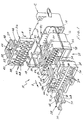
- the invention is embodied in a connector position assurance system for an electrical connector, generally designated 10, which is adapted for mating with another mateable connecting device shown herein as a header connector, generally designated 12.
- Header connector 12 includes a large receptacle 14 for receiving a mating end 16 of connector 10, as well as a smaller receptacle 18 for receiving the mating end of a second connector described hereinafter in relation to Figures 3 and 4.
- the second connector, as well as the terminals of the connector assembly, are not shown in Figure 1 in order to avoid cluttering the drawing which would detract from a clear depiction of the components of electrical connector 10.
- electrical connector 10 is comprised of four components, namely: a housing means, generally designated 20, which includes a front housing part 22 and a rear housing part 24; a terminal position assurance device (TPA), generally designated 26; and a connector position assurance device (CPA), generally designated 28.
- TPA 26 is mountable on front housing part 22 by inserting the TPA into a slot 30 in the direction of arrow "A”.
- CPA 28 is mountable within a cage 32 of rear housing part 24 in the direction of arrow "B".
- Front housing part 22 has two rows of terminal-receiving passages 34
- rear housing part 24 has two rows of-terminal-receiving passages 36
- TPA 26 has two rows of terminal-receiving passages 38, all of which are aligned when connector 20 is assembled.
- the TPA has narrowed portions 40 between passages 38 which will abut against portions of any terminal which is not fully inserted into the connector and, thereby, prevent the TPA from being fully inserted into front housing part 22 in the direction of arrow "A". Therefore, the incompletely inserted TPA will indicate that one or more terminals are not fully inserted into connector housing means 20.
- narrowed portions 40 will act as a secondary locking feature to retain the fully-inserted terminals in their correct positions, along with the primary locking arm discussed in more detail below.
- TPA 26 basically is a generally rectangular block 42 having terminal-receiving passages 38 extending therethrough.
- a pair of mounting arms 44 project forwardly of block 42 and are insertable into appropriate mounting grooves 46 in the top of front housing part 22.
- a generally U-shaped CPA guide structure 48 also projects forwardly of block 42 at the top thereof.
- the guide structure includes a pair of generally parallel guide rails 50 which have interior guide channels formed by angled interior walls 52.
- Front housing part 22 of connector 10 also has a pair of guide rails 54 defining interior guide channels formed by angled interior walls 56.
- guide rails 50 and interior guide channels 52 of the TPA are in alignment with guide rails 54 and interior guide channels 56 of the front housing part.
- Rear housing part 24 of connector 10 includes a relatively movable locking arm 58 which is attached to the rear housing part by an integrally molded, flexible fulcrum 60.
- the latch arm has a central slot 62 which terminates in a rearwardly facing shoulder 64 which defines a latch for the locking arm which resiliently snaps behind a latch boss 65 on header connector 12.
- CPA 28 of connector 10 is mountable within cage 32 of rear housing part 24 on top of locking arm 58 in the direction of arrow "B".
- Cage 32 has a pair of spaced, parallel guide rails 66 which are aligned with guide rails 54 of front housing part 22 and guide rails 50 of TPA 26 when the connector is assembled.
- CPA 28 has a pair of generally parallel guide rails 68 having outwardly flared or enlarged bottom edges defined by outwardly angled side walls 70. These enlarged, outwardly flared bottom edges of guide rails 68 are captured within interior guide channels 56 of guide rails 54 and interior guide channels 52 of guide rails 50 of front housing part 22 and TPA 26, respectively.
- CPA 28 cannot be lifted off of the connector assembly, because outwardly flared lower edges 70 of guide rails 68 are captured within the interior guide channels of the front housing part and the TPA, as well as within the short guide rails 66 of the rear housing part.
- CPA 28 also has a forwardly projecting actuating arm 72 having a downwardly angled front latching tip 74.
- the front latching tip rides within slot 62 of locking arm 58 for purposes described hereinafter.
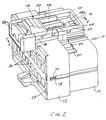
- FIG. 2 shows electrical connector 10 of Figure 1 in fully assembled condition. It can be seen that TPA 26 has been fully inserted downwardly into slot 30 of front housing part 22, with the rear housing part 24 assembled to the front housing part. It can be seen that the rear housing part has a pair of side latch bosses 76 which snap into a pair of complementary side latch apertures 78 in the front housing part.
- CPA 28 is shown in assembled condition with guide rails 68 slidably movable between guide rails 54 of the rear housing part and guide rails 50 of the TPA. It also can be seen that front latching tip 74 of actuating arm 72 of the CPA is disposed within slot 62 of locking arm 58.
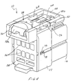
- Figures 3 and 4 show a second electrical connector, generally designated 10A, which is substantially identical to connector 10 (Figs. 1 and 2), except that connector 10A is sized for insertion into the smaller receptacle 18 (Fig. 1) of header connector 12. Except for the size differential, connector 10A is substantially identical to connector 10 in structure, assembly and function. In other words, connector 10A includes a front housing part 22, a rear housing part 24, a TPA 26 and a CPA 28. Therefore, like reference numerals have been applied in Figures 3 and 4 corresponding to like components described above in relation to connector 10 in Figures 1 and 2.
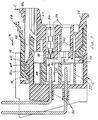
- FIGS 5-7 show sequential views of the assembly of connector 10 with header connector 12 as well as the functioning of locking arm 58 and CPA 28.
- one of the terminals, generally designated 80, of the connector assembly has been inserted into one of the terminal-receiving passages 36 of rear housing part 24, one of the terminal-receiving passages 38 of TPA 26 and one of the terminal-receiving passages 34 of front housing part 22.
- one of the terminals 80 will be inserted into each of the terminal-receiving passages in the housing parts and the TPA.
- rear housing part 24 has a primary locking arm 82 with a forwardly facing locking shoulder 84 within each of the composite terminal-receiving passages. Locking shoulder 84 of each primary locking arm is adapted for locking behind a shoulder 86 of the respective terminal inserted into the adjacent passage.
- an enlarged front portion 88 of the terminal will block movement of the enlarged portions 40 (Fig. 1) of the TPA and, thereby, prevent the TPA from moving to is final terminal position assurance position.
- a pair of terminal pins 90 are shown mounted within header connector 12 for mating engagement with terminals 80 of connector 10. If TPA 26 is not fully inserted to the position shown in Figures 5-7, it will block full assembly of the two housing parts due to mounting arms 44 of block 42 stubbing on or interfering with slot walls 87 in front housing part 22.
- Figure 5 shows connector 10 just slightly prior to insertion into header connector 12 in the direction of arrow "E".
- front latching tip 74 of actuating arm 72 of CPA 28 abuts against latch shoulder 64 of locking arm 58. This prevents the CPA from inadvertently moving to its final locking position before the connectors are mated.
- CPA 28 is maintained in a preload position shown in Figure 5 prior to latching of connectors 10 and 12.
- Figure 5 shows the front end 58b of locking arm 58, immediately forward of latching shoulder 64, riding up an angled surface 65a of latch 65 on header connector 12.
- FIG. 6 shows connector 10 fully mated and latched with header connector 12. It can be seen that latch shoulder 64 at the front of locking arm 58 has resiliently snapped behind latch 65 of the header connector. During final latching movement between the connectors, front latching tip 74 of actuating arm 72 of the CPA rides up angled surface 65a of latch 65 as indicated by arrow "F". Latching tip 74, thereby, is moved out of locking engagement with latch shoulder 64 and now can be moved forwardly in the direction of arrow "G".
- FIG. 7 shows CPA 28 having been moved forwardly in the direction of arrow "G” until front latching tip 74 of actuating arm 72 snaps over the front end 58b of locking arm 58.
- the outside surface of front end 58b of locking arm 58 has an angled or wedged surface 89 ( Figures 1 and 3) which opposes a wedged surface (not shown) along an inside wall of rail 68 to prevent locking arm 58 from moving upward and to therefore retain the locking arm in its locked position particularly in the event that pressure is applied to the rear end 58a of the locking arm in the direction of arrow "C".
- CPA 28 When it is desired to unmate connectors 10 and 12, CPA 28 is moved rearwardly opposite the direction of arrow "G" from the final position shown in Figure 7 to the preload position shown in Figure 6.
- the rear end 58a of locking arm 58 then can be depressed as shown in Figure 5 to lift latch 64 of connector 10 off of latch 65 of header connector 12, and the connectors can be unmated.
- Second connector 10A being of substantially identical structure to connector 10, functions substantially identical to the description of connector 10 in relation to Figures 5-7. Therefore, the description will not be repeated.
Landscapes
- Details Of Connecting Devices For Male And Female Coupling (AREA)
- Coupling Device And Connection With Printed Circuit (AREA)
- Connector Housings Or Holding Contact Members (AREA)
Applications Claiming Priority (2)
| Application Number | Priority Date | Filing Date | Title |
|---|---|---|---|
| US09/064,356 US5928038A (en) | 1998-04-24 | 1998-04-24 | Electrical connector position assurance system |
| US64356 | 1998-04-24 |
Publications (2)
| Publication Number | Publication Date |
|---|---|
| EP0952634A2 true EP0952634A2 (fr) | 1999-10-27 |
| EP0952634A3 EP0952634A3 (fr) | 2001-04-04 |
Family
ID=22055378
Family Applications (1)
| Application Number | Title | Priority Date | Filing Date |
|---|---|---|---|
| EP99108055A Withdrawn EP0952634A3 (fr) | 1998-04-24 | 1999-04-23 | Système d'assurance de position d'un connecteur électrique |
Country Status (4)
| Country | Link |
|---|---|
| US (1) | US5928038A (fr) |
| EP (1) | EP0952634A3 (fr) |
| JP (1) | JP3092066B2 (fr) |
| KR (1) | KR19990083451A (fr) |
Cited By (2)
| Publication number | Priority date | Publication date | Assignee | Title |
|---|---|---|---|---|
| CN111316504A (zh) * | 2017-09-07 | 2020-06-19 | 赫斯曼汽车有限公司 | 具有用于将触点配合件固定在其触点承载件中的次级锁定件的插接连接器 |
| US12531373B2 (en) * | 2021-12-03 | 2026-01-20 | Neutrik Ag | Unlocking element and electrical plug-in provided therewith |
Families Citing this family (96)
| Publication number | Priority date | Publication date | Assignee | Title |
|---|---|---|---|---|
| JP3420918B2 (ja) * | 1997-09-17 | 2003-06-30 | 矢崎総業株式会社 | 半嵌合防止コネクタ |
| JP3693149B2 (ja) * | 1999-01-11 | 2005-09-07 | 住友電装株式会社 | コネクタ |
| JP3494285B2 (ja) * | 1999-10-21 | 2004-02-09 | 住友電装株式会社 | コネクタ |
| US6354860B1 (en) * | 1999-11-01 | 2002-03-12 | Osram Sylvania Inc. | Connector and connector assembly |
| JP3463636B2 (ja) * | 1999-12-13 | 2003-11-05 | 住友電装株式会社 | コネクタ |
| JP3672229B2 (ja) * | 2000-02-23 | 2005-07-20 | 矢崎総業株式会社 | ホルダ抜け防止コネクタ |
| US6305990B1 (en) * | 2000-05-08 | 2001-10-23 | Tyco Electronics Corp | Sealed electrical connector with secondary locking |
| JP3555591B2 (ja) * | 2001-04-26 | 2004-08-18 | 住友電装株式会社 | コネクタ |
| JP3976134B2 (ja) * | 2001-09-05 | 2007-09-12 | 矢崎総業株式会社 | 半嵌合防止コネクタ |
| US6491542B1 (en) * | 2002-01-16 | 2002-12-10 | Yazaki North America | Combined connection and terminal position assurance structure for vehicle wiring connectors |
| US6780045B2 (en) | 2002-03-06 | 2004-08-24 | Tyco Electronics Corporation | Connector position assurance device |
| JP4219612B2 (ja) * | 2002-05-10 | 2009-02-04 | 古河電気工業株式会社 | 二重ロックコネクタ |
| US6913494B2 (en) * | 2002-07-17 | 2005-07-05 | Tyco Electronics Corporation | Electrical connector apparatus, methods and articles of manufacture |
| DE10334589B4 (de) * | 2002-07-29 | 2008-03-27 | Yazaki Corp. | Steckverbinder |
| US6648700B1 (en) * | 2003-02-20 | 2003-11-18 | Tyco Electronics Corporation | Stepped/keying interface stabilization alignment mechanism |
| FR2853770A1 (fr) * | 2003-04-11 | 2004-10-15 | Framatome Connectors Int | Connecteur electrique avec clip de retention pour maintenir au moins une borne de contact et procede de montage associe |
| US7201599B2 (en) * | 2004-03-23 | 2007-04-10 | Fci Americas Technology, Inc. | Electrical connector latch |
| FR2875957A1 (fr) * | 2004-09-29 | 2006-03-31 | Fci Sa | Dispositif de verrouillage d'elements de connecteur et connecteur le comprenant |
| KR100599313B1 (ko) * | 2004-11-12 | 2006-07-18 | 현대자동차주식회사 | 와이어하니스 커넥터 |
| DE102005013633B4 (de) * | 2005-03-24 | 2012-11-08 | Amphenol-Tuchel Electronics Gmbh | Stecksystem für elektrische Steckverbinder |
| US7048583B1 (en) * | 2005-04-25 | 2006-05-23 | J.S.T. Corporation | Electrical connector with a terminal position assurance mechanism |
| US7179135B2 (en) * | 2005-04-25 | 2007-02-20 | J.S. T. Corporation | Electrical connector with a terminal position assurance mechanism |
| US7744390B2 (en) * | 2005-07-28 | 2010-06-29 | Fci Americas Technology, Inc. | Electrical connector assembly with connection assist |
| US7241155B2 (en) * | 2005-07-28 | 2007-07-10 | Fci Americas Technology, Inc. | Electrical connector assembly with connection assist |
| US7223131B2 (en) * | 2005-09-02 | 2007-05-29 | Tyco Electronics Corporation | Three position electrical connector assembly |
| JP4747753B2 (ja) * | 2005-09-14 | 2011-08-17 | 住友電装株式会社 | コネクタ |
| US7361036B2 (en) * | 2005-10-06 | 2008-04-22 | Fci Americas Technology, Inc. | Electrical connector with lever and latch |
| US7255593B2 (en) * | 2006-01-09 | 2007-08-14 | Fci Americas Technology, Inc. | Electrical connector with connector position assurance (CPA) member |
| US7387545B2 (en) | 2006-03-24 | 2008-06-17 | Fci Americas Technology, Inc. | Electrical connector with pre-locked terminal position assurance (TPA) |
| KR100809560B1 (ko) | 2006-06-19 | 2008-03-04 | 한국몰렉스 주식회사 | 암커넥터의 tpa 설치구조 |
| KR100858755B1 (ko) | 2006-11-20 | 2008-09-16 | 에프씨아이 커넥터즈 싱가포르 피티이 엘티디. | 전기 커넥터 및 커넥터 조립체 |
| US7399195B2 (en) * | 2006-12-06 | 2008-07-15 | J.S.T. Corporation | Connector position assurance device and connector assembly incorporating the same |
| JP2008153103A (ja) * | 2006-12-19 | 2008-07-03 | Sumitomo Wiring Syst Ltd | コネクタ |
| US7347745B1 (en) * | 2007-01-19 | 2008-03-25 | Tyco Electronics Corporation | Three position electrical connector assembly |
| KR100818629B1 (ko) * | 2007-02-23 | 2008-04-02 | 한국단자공업 주식회사 | 위치확보부재를 포함하는 커넥터 어셈블리 |
| JP2009021159A (ja) * | 2007-07-13 | 2009-01-29 | Tyco Electronics Amp Kk | 電気コネクタ組立体、雄型コネクタ |
| US7553179B2 (en) * | 2007-08-07 | 2009-06-30 | Itt Manufacturing Enterprises, Inc. | Connector latch retainer |
| US7682205B2 (en) * | 2007-11-15 | 2010-03-23 | Tyco Electronics Corporation | Multi position electrical connector assembly |
| CH702048B1 (de) * | 2008-03-14 | 2011-04-29 | Huber+Suhner Ag | Mehrfach-Koaxialkabel-Steckverbindung sowie Verfahren zum Montieren einer solchen Mehrfach-Koaxialkabel-Steckverbindung. |
| US20090247011A1 (en) * | 2008-03-27 | 2009-10-01 | John Mark Myer | Connector assembly having primary and secondary locking features |
| DE102008035193A1 (de) * | 2008-07-28 | 2010-02-11 | Tyco Electronics Amp Gmbh | Kontrollierbare Steckverbindung und Verfahren zur Kontrolle des Steckzustandes einer Steckverbindung |
| JP5341477B2 (ja) * | 2008-11-04 | 2013-11-13 | 矢崎総業株式会社 | コネクタ |
| DE102008057467B3 (de) | 2008-11-14 | 2010-04-08 | Amphenol-Tuchel Electronics Gmbh | Vormontierbares Steckverbindersystem |
| JP5506439B2 (ja) * | 2010-02-05 | 2014-05-28 | 矢崎総業株式会社 | コネクタ |
| JP5653150B2 (ja) * | 2010-09-16 | 2015-01-14 | 矢崎総業株式会社 | 半嵌合防止コネクタ |
| DE102010042826B3 (de) * | 2010-10-22 | 2012-03-15 | Tyco Electronics Amp Gmbh | Elektrisches Steckerelement mit Kontaktsicherungsorgan und Prüfanschlag |
| KR101717114B1 (ko) * | 2010-11-12 | 2017-03-16 | 한국단자공업 주식회사 | 인터락 커넥터조립체 |
| US8419485B2 (en) * | 2011-01-27 | 2013-04-16 | Tyco Electronics Corporation | Bulkhead connector assembly |
| JP5644657B2 (ja) * | 2011-05-10 | 2014-12-24 | 住友電装株式会社 | 車載用電気機器のシールカバー |
| JP5704031B2 (ja) * | 2011-09-24 | 2015-04-22 | 住友電装株式会社 | コネクタ |
| US8678846B2 (en) * | 2012-03-28 | 2014-03-25 | Tyco Electronics Corporation | Electrical connector with connector position assurance device |
| KR101337937B1 (ko) * | 2012-05-04 | 2013-12-09 | 현대자동차주식회사 | 연료전지 스택의 셀 전압 측정용 커넥터 |
| US8926355B2 (en) * | 2012-06-29 | 2015-01-06 | Lear Corporation | Connector position assurance device for a connector assembly |
| US9318836B2 (en) * | 2014-02-06 | 2016-04-19 | Dai-Ichi Seiko Co., Ltd. | Electric connector |
| US9666972B2 (en) * | 2014-11-13 | 2017-05-30 | Te Connectivity Corporation | Electrical connector |
| JP6372428B2 (ja) * | 2015-06-22 | 2018-08-15 | 株式会社オートネットワーク技術研究所 | ジョイントコネクタ |
| JP2017084486A (ja) * | 2015-10-23 | 2017-05-18 | タイコエレクトロニクスジャパン合同会社 | コネクタ |
| JP6244345B2 (ja) * | 2015-10-28 | 2017-12-06 | 矢崎総業株式会社 | コネクタ |
| US10109955B2 (en) | 2016-01-14 | 2018-10-23 | J.S.T. Corporation | Electrical connector apparatus having a male housing and a female housing with ribs |
| US10673168B2 (en) * | 2016-01-14 | 2020-06-02 | J.S.T. Corporation | MSL connector series |
| US10622746B2 (en) | 2016-01-15 | 2020-04-14 | J.S.T. Corporation | Terminal position assurance member and method of operating a terminal position assurance member |
| US9912092B2 (en) * | 2016-01-29 | 2018-03-06 | Te Connectivity Corporation | Ergonomic terminal position assurance member |
| FR3051080B1 (fr) * | 2016-05-09 | 2022-07-22 | Delphi Int Operations Luxembourg Sarl | Ensemble de connexion et procede d'assemblage de cet ensemble de connexion |
| ES2906252T3 (es) | 2016-08-25 | 2022-04-13 | Itt Mfg Enterprises Llc | Interconexión de sellado de perfil bajo con interfaz de enganche |
| USD818962S1 (en) | 2017-03-02 | 2018-05-29 | Molex, Llc | Connector shell |
| USD835044S1 (en) | 2017-03-02 | 2018-12-04 | Molex, Llc | Connector housing |
| USD821974S1 (en) | 2017-03-02 | 2018-07-03 | Molex, Llc | Connector shell |
| USD831574S1 (en) | 2017-03-02 | 2018-10-23 | Molex, Llc | Connector housing |
| USD829658S1 (en) | 2017-03-02 | 2018-10-02 | Molex, Llc | Connector assembly |
| JP6891699B2 (ja) * | 2017-07-26 | 2021-06-18 | I−Pex株式会社 | 嵌合検知コネクタ装置および雌コネクタ |
| JP6891700B2 (ja) * | 2017-07-26 | 2021-06-18 | I−Pex株式会社 | 嵌合検知コネクタ装置および雌コネクタ |
| US10283904B2 (en) * | 2017-08-04 | 2019-05-07 | Yazaki Corporation | Connector |
| CN111066207B (zh) * | 2017-08-31 | 2021-04-23 | 矢崎总业株式会社 | 部件锁定结构 |
| US20190140386A1 (en) * | 2017-11-08 | 2019-05-09 | GM Global Technology Operations LLC | Inline connector tpa terminal stabilizer |
| US10355414B1 (en) | 2018-02-08 | 2019-07-16 | Delphi Technologies, Llc | Connector with a connector position assurance device |
| WO2019178520A1 (fr) * | 2018-03-16 | 2019-09-19 | Fci Usa Llc | Connecteurs électriques à haute densité |
| JP6800921B2 (ja) * | 2018-08-01 | 2020-12-16 | 矢崎総業株式会社 | コネクタ |
| US10566728B1 (en) * | 2018-10-30 | 2020-02-18 | Aptiv Technologies Limited | Electrical connector with high vibration resistant locks |
| CN110212357B (zh) * | 2018-12-05 | 2021-03-23 | 中航光电科技股份有限公司 | 连接器及其接触件锁止件 |
| KR101998077B1 (ko) * | 2019-01-23 | 2019-07-09 | (주)우주일렉트로닉스 | 커넥터위치보증부재를 갖는 커넥터 장치 |
| USD925456S1 (en) * | 2019-02-28 | 2021-07-20 | Molex, Llc | Connector |
| DE102019004712A1 (de) * | 2019-07-04 | 2021-01-07 | Kostal Kontakt Systeme Gmbh | Mehrpolige Steckverbinderanordnung |
| US11962106B2 (en) * | 2019-07-18 | 2024-04-16 | Tyco Electronics Japan G.K. | Connector |
| CN112448218B (zh) * | 2019-08-27 | 2022-05-03 | 胡连电子(南京)有限公司 | 一种防止带电拔插的连接器 |
| US11456553B2 (en) * | 2019-09-19 | 2022-09-27 | J.S.T. Corporation | Low profile high voltage connector and method for assemblying thereof |
| KR102911843B1 (ko) | 2019-11-12 | 2026-01-14 | 현대자동차주식회사 | 연료 전지에 탈착 가능한 셀 모니터링 커넥터 |
| JP7414635B2 (ja) * | 2020-05-07 | 2024-01-16 | 日本航空電子工業株式会社 | コネクタ組立体 |
| DE102020210760A1 (de) * | 2020-08-25 | 2022-03-03 | Te Connectivity Germany Gmbh | Stecker mit einem Lagesicherungselement mit einer Kontaktaufnahme |
| DE102020122660A1 (de) * | 2020-08-31 | 2022-03-03 | Md Elektronik Gmbh | Verbindungsvorrichtung mit einem Steckverbinder und einem Gegensteckverbinder |
| US11837806B2 (en) | 2020-12-09 | 2023-12-05 | Lear Corporation | Grounding electrical connector |
| CN114843815B (zh) * | 2021-02-02 | 2026-01-23 | 泰科电子(上海)有限公司 | 电连接器 |
| JP7393386B2 (ja) * | 2021-06-04 | 2023-12-06 | 矢崎総業株式会社 | コネクタ |
| TWM629291U (zh) | 2021-07-07 | 2022-07-11 | 大陸商富加宜電子(南通)有限公司 | 一種混合式連接器 |
| CN115732972A (zh) * | 2021-08-31 | 2023-03-03 | 华为技术有限公司 | 连接器、其制作方法及相关设备 |
| KR20230052072A (ko) * | 2021-10-12 | 2023-04-19 | 현대자동차주식회사 | 연료 전지용 셀 모니터링 커넥터 |
| JP2025179560A (ja) * | 2024-05-28 | 2025-12-10 | 住友電装株式会社 | コネクタ |
Family Cites Families (25)
| Publication number | Priority date | Publication date | Assignee | Title |
|---|---|---|---|---|
| US5120255A (en) * | 1990-03-01 | 1992-06-09 | Yazaki Corporation | Complete locking confirming device for confirming the complete locking of an electric connector |
| US5217390A (en) * | 1990-04-16 | 1993-06-08 | Sumitomo Wiring Systems, Ltd. | Connector |
| GB9012060D0 (en) * | 1990-05-30 | 1990-07-18 | Amp Great Britain | Electrical connector housings |
| US5026298A (en) * | 1990-07-23 | 1991-06-25 | General Motors Corporation | Electrical connector with connector position assurance device |
| GB2249438B (en) * | 1990-10-08 | 1995-01-18 | Sumitomo Wiring Systems | Connector |
| JP2500721Y2 (ja) * | 1990-10-12 | 1996-06-12 | 矢崎総業株式会社 | 半嵌合防止コネクタ |
| JP2563323Y2 (ja) * | 1990-10-22 | 1998-02-18 | 矢崎総業株式会社 | コネクタ |
| JP2501005Y2 (ja) * | 1990-10-31 | 1996-06-12 | 矢崎総業株式会社 | コネクタ |
| JP2571310B2 (ja) * | 1990-12-14 | 1997-01-16 | 矢崎総業株式会社 | コネクタのロック保障機構 |
| JP2523705Y2 (ja) * | 1991-08-26 | 1997-01-29 | 矢崎総業株式会社 | 自動車用電気接続装置 |
| US5120240A (en) * | 1991-09-03 | 1992-06-09 | General Motors Corporation | Electrical connector with improved connector position assurance device |
| JPH05135823A (ja) * | 1991-11-11 | 1993-06-01 | Yazaki Corp | コネクタのロツク装置 |
| US5507666A (en) * | 1993-12-28 | 1996-04-16 | Yazaki Corporation | Lock securing mechanism for connectors |
| JP2907377B2 (ja) * | 1994-06-03 | 1999-06-21 | 矢崎総業株式会社 | コネクタの結合検知装置 |
| US5618201A (en) * | 1994-06-14 | 1997-04-08 | Yazaki Corporation | Connector having engagement detecting device |
| US5672073A (en) * | 1994-06-14 | 1997-09-30 | Yazaki Corporation | Connector having engagement detecting device |
| JP2921645B2 (ja) * | 1994-07-12 | 1999-07-19 | 矢崎総業株式会社 | コネクタ嵌合検知構造 |
| JP3098938B2 (ja) * | 1994-08-10 | 2000-10-16 | 矢崎総業株式会社 | コネクタ |
| JP2982107B2 (ja) * | 1994-10-19 | 1999-11-22 | 矢崎総業株式会社 | コネクタの半嵌合検知構造 |
| US5605471A (en) * | 1995-02-01 | 1997-02-25 | United Technologies Automotive, Inc. | Electrical connector assembly employing a connector position assurance device |
| US5628648A (en) * | 1995-03-17 | 1997-05-13 | Molex Incorporated | Electrical connector position assurance system |
| US5643003A (en) * | 1995-06-02 | 1997-07-01 | The Whitaker Corporation | Housing latch with connector position assurance device |
| JP3125846B2 (ja) * | 1995-06-09 | 2001-01-22 | 矢崎総業株式会社 | 端子係止具を備えたコネクタ |
| US5681178A (en) * | 1995-06-27 | 1997-10-28 | The Whitaker Corporation | Electrical connector with connector position assurance device |
| FR2738081B1 (fr) * | 1995-08-22 | 1997-09-26 | Cinch Connecteurs Sa | Connecteur electrique |
-
1998
- 1998-04-24 US US09/064,356 patent/US5928038A/en not_active Expired - Lifetime
-
1999
- 1999-04-21 JP JP11113480A patent/JP3092066B2/ja not_active Expired - Fee Related
- 1999-04-23 EP EP99108055A patent/EP0952634A3/fr not_active Withdrawn
- 1999-04-23 KR KR1019990014706A patent/KR19990083451A/ko not_active Ceased
Cited By (2)
| Publication number | Priority date | Publication date | Assignee | Title |
|---|---|---|---|---|
| CN111316504A (zh) * | 2017-09-07 | 2020-06-19 | 赫斯曼汽车有限公司 | 具有用于将触点配合件固定在其触点承载件中的次级锁定件的插接连接器 |
| US12531373B2 (en) * | 2021-12-03 | 2026-01-20 | Neutrik Ag | Unlocking element and electrical plug-in provided therewith |
Also Published As
| Publication number | Publication date |
|---|---|
| EP0952634A3 (fr) | 2001-04-04 |
| KR19990083451A (ko) | 1999-11-25 |
| JP3092066B2 (ja) | 2000-09-25 |
| US5928038A (en) | 1999-07-27 |
| JPH11329585A (ja) | 1999-11-30 |
Similar Documents
| Publication | Publication Date | Title |
|---|---|---|
| US5928038A (en) | Electrical connector position assurance system | |
| EP0984522B1 (fr) | Connecteur électrique avec dispositif d'assurance de position | |
| EP3766139B1 (fr) | Connecteur électrique avec cpa | |
| US5591041A (en) | Electrical connector position assurance system | |
| JP6710310B2 (ja) | コネクタ位置保証を有するコネクタシステム | |
| US6533601B2 (en) | Electrical connector assembly with a laterally deflectable latch member and CPA | |
| EP0704934B1 (fr) | Connecteur électrique avec un dispositif pour assurer la position des terminaux facilitant l'insertion complète des terminaux | |
| US6811424B2 (en) | Electrical connector having connector position assurance member | |
| EP0804821B1 (fr) | Element d'encliquetage de boitier avec dispositif de verification de la position de connecteurs | |
| US6244880B1 (en) | Low-insertion force connector | |
| EP0923164B1 (fr) | Assemblage de connexion électrique avec un système de retenue des contacts | |
| US6716069B2 (en) | Connector with a housing and a retainer held securely on the housing | |
| EP0732775A2 (fr) | Système d'assurance de position d'un connecteur électrique | |
| EP0726617A2 (fr) | Connecteur avec verrouillage secondaire et mécanisme d'accouplement | |
| EP1054481A1 (fr) | Un connecteur | |
| US20060063414A1 (en) | Electrical connector having improved terminal positioning assurance member | |
| US5890935A (en) | Electrical connector with terminal position assurance device | |
| EP1094559B1 (fr) | Connecteur électrique ayant un dispositif de retenue des contacts | |
| US6682366B2 (en) | Connector | |
| US20240372297A1 (en) | Connector assembly with a terminal position assurance function integrated to a connector position assurance member | |
| KR102722218B1 (ko) | 커넥터 위치 보장 부재 | |
| US7063577B2 (en) | Split-type connector assembly and method of assembling it | |
| US20190252818A1 (en) | Connector | |
| EP0999614A2 (fr) | Connecteur électrique pourvu d'un membre de verrouillage | |
| US6478632B2 (en) | Shake preventing construction for a terminal fitting and a connector |
Legal Events
| Date | Code | Title | Description |
|---|---|---|---|
| PUAI | Public reference made under article 153(3) epc to a published international application that has entered the european phase |
Free format text: ORIGINAL CODE: 0009012 |
|
| AK | Designated contracting states |
Kind code of ref document: A2 Designated state(s): AT BE CH CY DE DK ES FI FR GB GR IE IT LI LU MC NL PT SE |
|
| AX | Request for extension of the european patent |
Free format text: AL;LT;LV;MK;RO;SI |
|
| PUAL | Search report despatched |
Free format text: ORIGINAL CODE: 0009013 |
|
| AK | Designated contracting states |
Kind code of ref document: A3 Designated state(s): AT BE CH CY DE DK ES FI FR GB GR IE IT LI LU MC NL PT SE |
|
| AX | Request for extension of the european patent |
Free format text: AL;LT;LV;MK;RO;SI |
|
| AKX | Designation fees paid | ||
| REG | Reference to a national code |
Ref country code: DE Ref legal event code: 8566 |
|
| STAA | Information on the status of an ep patent application or granted ep patent |
Free format text: STATUS: THE APPLICATION IS DEEMED TO BE WITHDRAWN |
|
| 18D | Application deemed to be withdrawn |
Effective date: 20011005 |