EP1094559B1 - Connecteur électrique ayant un dispositif de retenue des contacts - Google Patents
Connecteur électrique ayant un dispositif de retenue des contacts Download PDFInfo
- Publication number
- EP1094559B1 EP1094559B1 EP00122300A EP00122300A EP1094559B1 EP 1094559 B1 EP1094559 B1 EP 1094559B1 EP 00122300 A EP00122300 A EP 00122300A EP 00122300 A EP00122300 A EP 00122300A EP 1094559 B1 EP1094559 B1 EP 1094559B1
- Authority
- EP
- European Patent Office
- Prior art keywords
- housing
- retainer
- lock arm
- lock
- detecting
- Prior art date
- Legal status (The legal status is an assumption and is not a legal conclusion. Google has not performed a legal analysis and makes no representation as to the accuracy of the status listed.)
- Expired - Lifetime
Links
- 230000013011 mating Effects 0.000 claims description 12
- 230000005489 elastic deformation Effects 0.000 claims description 10
- 238000003780 insertion Methods 0.000 claims description 9
- 230000037431 insertion Effects 0.000 claims description 9
- 230000002452 interceptive effect Effects 0.000 claims description 2
- 229920003002 synthetic resin Polymers 0.000 description 3
- 239000000057 synthetic resin Substances 0.000 description 3
- 230000001419 dependent effect Effects 0.000 description 1
- 238000004519 manufacturing process Methods 0.000 description 1
- 238000000034 method Methods 0.000 description 1
Images


Classifications
-
- H—ELECTRICITY
- H01—ELECTRIC ELEMENTS
- H01R—ELECTRICALLY-CONDUCTIVE CONNECTIONS; STRUCTURAL ASSOCIATIONS OF A PLURALITY OF MUTUALLY-INSULATED ELECTRICAL CONNECTING ELEMENTS; COUPLING DEVICES; CURRENT COLLECTORS
- H01R13/00—Details of coupling devices of the kinds covered by groups H01R12/70 or H01R24/00 - H01R33/00
- H01R13/40—Securing contact members in or to a base or case; Insulating of contact members
- H01R13/42—Securing in a demountable manner
- H01R13/436—Securing a plurality of contact members by one locking piece or operation
- H01R13/4361—Insertion of locking piece perpendicular to direction of contact insertion
- H01R13/4362—Insertion of locking piece perpendicular to direction of contact insertion comprising a temporary and a final locking position
-
- H—ELECTRICITY
- H01—ELECTRIC ELEMENTS
- H01R—ELECTRICALLY-CONDUCTIVE CONNECTIONS; STRUCTURAL ASSOCIATIONS OF A PLURALITY OF MUTUALLY-INSULATED ELECTRICAL CONNECTING ELEMENTS; COUPLING DEVICES; CURRENT COLLECTORS
- H01R13/00—Details of coupling devices of the kinds covered by groups H01R12/70 or H01R24/00 - H01R33/00
- H01R13/62—Means for facilitating engagement or disengagement of coupling parts or for holding them in engagement
- H01R13/627—Snap or like fastening
- H01R13/6271—Latching means integral with the housing
- H01R13/6272—Latching means integral with the housing comprising a single latching arm
Definitions
- the present invention relates to a connector provided with a retainer.
- a known connector of this type is disclosed in Japanese Patent Publication No. 2627357 schematically shown in FIGS. 12 and 13.
- This connector 1 is provided with a housing 2 formed with cavities for accommodating terminal fittings, and a retainer 3 mountable in the housing 2 in a direction intersecting with an inserting direction of the terminal fittings.
- the retainer 3 locks the terminal fittings to prevent them from coming out.
- the housing 2 is connected with a mating housing 4 by inserting the housing 2 into a receptacle 5 of the mating housing 4.
- the retainer 3 If the retainer 3 is partly mounted without being pushed to its full locking position, it projects from the housing 2, thereby interfering the opening edge of the receptacle 5 while the housings 2, 4 are being connected (see FIG. 12). Partial mounting of the retainer 3 can be detected since the housing 2 cannot be fitted into the receptacle 5 any further.
- EP-A-0 851 535 discloses a connector having a retainer to lock terminal fittings in cavities of a housing of the connector. This retainer is provided with an escaping portion facing a lock arm to permit an elastic deformation of the lock arm in a full locking position of the retainer, so that the housing of the connector is allowed to be connected with a mating housing.
- US-A-5 037 336 discloses a connector having a retainer to lock terminal fittings in cavities of a housing of the connector. This retainer is lockable in a temporary position and a final position by means of latching devices.
- the present invention was developed in view of the above problem, and an object thereof is to provide a connector which can securely detect partial mounting of a retainer.
- the retainer is insertable into the housing in a direction intersecting with an inserting direction of the terminal fittings.
- a connector comprising:
- the escaping portion is aligned with the lock arm in the deforming direction.
- the lock arm is permitted to undergo a specified degree of elastic deformation by entering the escaping portion.
- the retainer is partly mounted without reaching the full locking position, the escaping portion is not aligned with the lock arm. Since the insertion of the housing into the receptacle of the mating housing is hindered, the lock arm is not permitted to undergo a sufficient degree of elastic deformation.
- partial mounting of the retainer is detected based on whether or not the housings can be connected with each other by using the elastically deformable lock arm as a detecting means.
- the retainer comprises:
- the retainer further comprises a holding piece which is provided at the substantially opposite side of the main body from the detecting piece and located outside the housing.
- the detecting piece and/or the holding piece are provided with a locking portion for the housing to prevent the entire retainer from coming out of the housing.
- the retainer comprises a main body to be inserted into the housing through an insertion opening formed in a side surface of the housing to lock the terminal fittings so as not to come out of the cavities, and a detecting piece which is so located outside the housing as to face the lock arm in the deforming direction, wherein the detecting piece is provided with a locking portion for engaging the housing to prevent the entire retainer from coming out of the housing.
- the detecting piece is so located outside the housing as to face the lock arm in the deforming direction, and the locking portion of this detecting piece securely holds the retainer in the full locking position so that the escaping portion securely faces the lock arm in the deforming direction.
- partial mounting of the retainer can be securely detected.
- the retainer further comprises a holding piece which is provided at the opposite side of the main body from the detecting piece and located outside the housing, the holding piece being also provided with a locking portion for engaging the housing.
- the connector can stably hold the retainer.
- the retainer is movable with respect to the housing between a partial locking position where insertion and withdrawal of the terminal fittings into and from the cavities are permitted and the full locking position.
- the retainer is prevented from coming out of the housing by being held in the partial locking position where insertion and withdrawal of the terminal fittings are permitted.
- This makes it easier to transport an assembly of partly mounted housing and retainer to a location where the terminal fittings are inserted and to insert the terminal fittings into the housing. Therefore, the connector is allowed to have an improved assembling operability.
- the escaping portion comprises a slanted portion being slanted towards the housing with an angle of inclination substantially corresponding to a deformation angle of the deformed lock arm.
- one of the lock arm and the escaping portion comprises a detecting projection and the other of the lock arm and the escaping portion comprises a mating detecting recess, wherein the detecting projection is allowed to be inserted into the detecting recess when the retainer is positioned or arranged in the full lock position so as to allow the elastic deflection of the lock arm.
- the escaping portion comprises a recess having a lateral width substantially corresponding to the lateral width of the lock arm so that the lock arm can be at least partly inserted into the recess upon deflection, when the retainer is positioned in the full lock position, whereby the housings are allowed to be connected.
- a connector 10 according to this embodiment is comprised of a male housing 12 and a female housing 11 as shown in FIG. 1.
- the male housing 12 has a main body 12B made e.g. of a synthetic resin and having a shape of a substantially rectangular column, and a plurality of cavities 12C are so formed as to substantially penetrate through the main body 12B in longitudinal or forward and backward directions for at least partly accommodating unillustrated terminal fittings.
- the male housing 12 is also provided with a substantially tubular receptacle 12A which at least partly surrounds a front half of the main body 12B.
- a housing lock 13 projects from the inner side of an opening edge of the receptacle 12A. The housing lock 13 is engageable with a lock arm 14 of the female housing 11 to be described later.
- the female housing 11 is made e.g. of a synthetic resin and has a shape of a substantially rectangular column.
- a plurality of cavities 11C are so formed as to substantially penetrate through the female housing 11 in longitudinal or forward and backward directions for at least partly accommodating unillustrated female terminal fittings.
- the lock arm 14 cantilevers backward in a position corresponding to the housing lock 13, preferably in the substantially middle of the upper surface of the female housing 11 with respect to widthwise direction.
- the lock arm 14 is elastically deformable upward and downward or toward and away from the female housing 11, and a locking projection 14A is formed on the upper surface of its rear end.
- the lock arm 14 moves under or cooperates with the housing lock 13 while having its rear end elastically deformed in a deformation direction D, e.g.
- the lock arm 14 passes the housing lock 13 to be elastically restored substantially to its original shape. In this way, the locking projection 14A engages the housing lock 13 to lock the housings 11, 12 into each other.
- the terminal fittings (not shown) accommodated in the housings 11, 12 are electrically connected in this state.
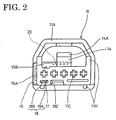
- an operable portion 11A which radially projects preferably over the substantially entire circumference of the female housing 11 and whose upper half is substantially arch-shaped (see FIG. 2). An operator can insert and withdraw the female housing 11 into and from the male housing 12 while holding or manipulating the operable portion 11A.
- Guiding projections 11H project from the upper and lower or lateral surfaces of the female housing 11, and unillustrated guide grooves corresponding thereto are formed in the receptacle 12A of the male housing 12.
- the housings 11, 12 can be stably fitted substantially without shaking by inserting the female housing 11 into the male housing 12 while engaging the guiding projections 11H with the guide grooves.
- the female housing 11 is formed with a retainer accommodating portion 16 which extends in a direction intersecting with an inserting direction of unillustrated terminal fittings.
- One end of the retainer accommodating portion 16 is open preferably in the substantially middle of one side surface of the female housing 11, thereby forming an insertion opening 16A (see FIG. 3).
- the retainer accommodating portion 16 is so formed as to substantially communicate with the respective cavities 11C.
- locking projections 17 substantially symmetrically project in positions on the upper and lower surfaces of the female housing 11 near the retainer accommodating portion 16A (see FIG. 5).
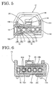
- a retainer 15 is integrally or unitarily formed e.g. of a synthetic resin and comprised of a main body 15A preferably in the form of a thick plate, a detecting piece 15B and a holding piece 15C which are provided preferably substantially above and below the main body 15A while defining clearances therebetween (see FIG. 6).
- the main body 15A is so formed as to be at least partly insertable into the retainer accommodating portion 16, and is formed with communication holes 15H which are aligned with the cavities 11C to communicate therewith (see FIGS. 1 and 6).
- Each communication hole 15H of the retainer 15 is formed with locking portions 15R.
- the detecting piece 15B is elastically deformably connected with one end of the main body 15A and substantially extends along the main body 15A.
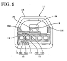
- the detecting piece 15B is located substantially in close contact with the upper surface of the female housing 11 and has such a length that its leading end crosses below or reaches the lock arm 14 when the retainer 15 is inserted to the proper mount position in the retainer accommodating portion 16 (see FIG. 9).
- the holding piece 15C is provided at the opposite side of the main body 15A from the detecting piece 15B, and cantilevers along the main body 15A from the same end of the main body 15A where the detecting piece 15B is provided in such a manner as to be elastically deformable.
- the holding piece 15C is located substantially in close contact with the lower surface of the female housing 11 when the retainer 15 is inserted into the retainer accommodating portion 16.
- the holding piece 15C is preferably shorter than the detecting piece 15B.
- locking recesses 18 are substantially symmetrically provided in positions of the inner surfaces of the detecting piece 15B and the holding piece 15C near their sides connected with the main body 15A.
- the locking recesses 18 include partial locking recesses 18A and full locking recesses 18B so as to be selectably engageable with the locking projections 17 (see FIGS. 5 and 9).
- the retainer 15 is held in a partial locking position with respect to the female housing 11, thereby permitting insertion and withdrawal of the terminal fittings into and from the cavities 11C (see FIG. 5).
- the retainer 15 When the retainer 15 is further inserted into the retainer accommodating portion 16 to engage the full locking recesses 18B and the locking projections 17, the retainer 15 is held in a full locking position where it engages the female terminal fittings (not shown) to lock preferably double-lock them in the cavities 11C (see FIG. 9).
- An escaping portion 20 for permitting an elastic deformation of the lock arm 14 is formed in the upper surface of the detecting piece 15B of the retainer 15 as shown in FIG. 7.
- the escaping portion 20 is formed in such a position that it is located below the lock arm 14 when the retainer 15 is held in the full locking position (see FIGS. 8 and 9).
- the width of the escaping portion 20 is preferably set substantially equal to or slightly larger than that of the lock arm 14.
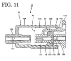
- the bottom surface of the escaping portion 20 is gradually slanted downward from its front end to its rear end such that an angle of inclination substantially corresponds to an angle or orientation of the deformed lock arm 14 when the locking projection 14A passes the housing lock 13 (see FIG. 10).
- the lock arm 14 Before the retainer 15 reaches the full locking position, the lock arm 14 is not substantially aligned with the escaping portion 20 and is interfered by the upper surface of the detecting piece 15B. Thus, the lock arm 14 is not permitted to deform to such a degree that the locking projection 14A can pass the housing lock 13 (see FIG. 11).
- the main body 15A of the retainer 15 is inserted into the retainer accommodating portion 16 through the retainer accommodating portion 16A of the female housing 11.
- the retainer 15 is guidably inserted into the retainer accommodating portion 16 while holding the female housing 11 by the detecting piece 15B and the holding piece 15C.
- the retainer 15 is held in its partial locking position in the female housing 11 (see FIG. 5).
- the connector 10 is transferred to a location of a terminal inserting process with the retainer 15 and the female housing 11 integrally assembled.
- the terminal fittings can be inserted into the cavities 11C since the locking portions 15R provided in the respective communication holes 15H of the retainer 15 do not project into the cavities 11C.
- the locking projections 17 engaged with the partial locking recesses 18A of the detecting piece 15B and the holding piece 15C are released from the partial locking recesses 18A by deformations of the detecting piece 15B and the holding piece 15C in opening directions and are engaged with the full locking recesses 18B, with the result that the retainer 15 is held in the full locking position (see FIG. 9).
- the locking portions 15R of the retainer 15 project into the cavities 11C to engage parts of the female terminal fittings (not shown) in the cavities 11C, thereby locking them.
- the female housing 11 is at least partly inserted into the receptacle 12A of the male housing 12.
- the locking projection 14A of the lock arm 14 comes into contact with the housing lock 13, and the lock arm 14 is elastically deformed downward (or away from the housing lock 13) to pass under (or over) the housing lock 13.
- the escaping portion 20 is substantially aligned right below the lock arm 14 in a deforming direction of the lock arm 14. Accordingly, the lock arm 14 is permitted to properly undergo an elastic deformation by the escaping portion 20 (see FIG. 10).
- the locking projection 14A can pass under the housing lock 13.
- the locking projection 14A and the housing lock 13 are engaged or interact with each other or cooperate to hold the male and female housings 11, 12 properly connected as shown in FIG. 1.
- the escaping portion 20 is not aligned with the lock arm 14. Accordingly, the lock arm 14 cannot be elastically deformed to such a degree as to permit the locking projection 14A to pass the housing lock 13 by being interfered by the detecting piece 15B. As a result, the female housing 11 cannot be inserted into the receptacle 12A of the male housing 12 (see FIG. 11).
- partial mounting of the retainer 15 is detected based on whether or not the housings 11, 12 can be connected with each other.
- the retainer is partly mounted such that it projects from the housing, it interferes the mating housing.
- a projecting amount of the retainer acts as a detecting means for detecting an impossibility to connect the housings with each other.
- the projecting amount is small, it might be offset by a connection clearance between the housings, with the result that partial mounting of the retainer may not be detected.
- the elastically deformable lock arm 14 is used as a detecting means, and a degree of elastic deformation of the lock arm 14 can be set independently of the connection clearance between the housings e.g. by adequately setting the projecting amount of the locking projection 14A.
- the position of the lock arm 14 where the connection of the male and female housings 11, 12 is permitted and that of the lock arm 14 where it is not permitted can be sufficiently spaced apart preferably by securing a sufficient depth of the escaping portion 20.
Landscapes
- Details Of Connecting Devices For Male And Female Coupling (AREA)
- Connector Housings Or Holding Contact Members (AREA)
Claims (9)
- Connecteur (10), comprenant :un boîtier (11) comportant à l'intérieur une ou plusieurs cavités (11C) pour recevoir au moins en partie une ou plusieurs armatures de bande correspondantes, et au moins partiellement ajustable dans un réceptacle (12A) d'un boîtier coopérant (12),une pièce de retenue (15) insérable dans le boîtier (11) et prévue pour verrouiller les armatures de borne dans les cavités (11C) lorsqu'elle est montée à une position de verrouillage total (figure 9),un bras de verrouillage (14) prévu sur le boîtier (11) et qui peut venir en prise avec le boîtier coopérant (12) afin d'empêcher les deux boîtiers (11, 12) de se séparer l'un de l'autre, etune partie d'échappement (20) prévue sur la pièce de retenue (15) dans une position en face du bras de verrouillage (14) dans une direction de déformation (D) pour permettre une déformation élastique du bras de verrouillage (14) seulement lorsque la pièce de retenue (15) atteint sensiblement la position de verrouillage total (figure 9) de sorte que les boîtiers (11, 12) peuvent s'accoupler,caractérisé par
un élément de détection (15B) prévu sur la pièce de retenue (15) et empêchant la déformation élastique du bras de verrouillage (14) à un degré tel que l'accouplement des boîtiers (11, 12) n'est pas permis, si la pièce de retenue (15) est partiellement montée (figure 5) de sorte que la partie d'échappement (20) n'est pas alignée avec le bras de verrouillage (14). - Connecteur selon la revendication 1, dans lequel la pièce de retenue (15) est insérable dans le boîtier (11) dans une direction en intersection avec une direction d'insertion des armatures de borne.
- Connecteur selon une ou plusieurs des revendications précédentes, dans lequel la pièce de retenue (15) comprend :un corps principal (15A) à insérer dans le boîtier (11) à travers une ouverture d'insertion (16A) formée de préférence dans une surface latérale du boîtier (11), pour verrouiller les armatures de borne afin qu'elles ne sortent pas des cavités (11C), etdans lequel le dit élément de détection (15B) est placé à l'extérieur du boîtier '11) de façon à faire sensiblement face au bras de verrouillage (14) dans la direction de déformation (D).
- Connecteur selon la revendication 3, dans lequel la pièce de retenue (15) comprend en outre un élément de maintien (15C) qui est prévu du côté du corps principal (15A) sensiblement à l'opposé de l'élément de détection (15B) et situé en dehors du boîtier (11).
- Connecteur selon la revendication 3 ou 4, dans lequel l'élément de détection (15B) et/ou l'élément de maintien (15C) comportent une partie de verrouillage (18) pour venir en prise avec le boîtier (11) afin d'empêcher la pièce de retenue entière (15) de sortir du boîtier (11).
- Connecteur selon une ou plusieurs des revendications précédentes, dans lequel la pièce de retenue (15) est déplaçable par rapport au boîtier (11) entre une position de verrouillage partiel (figure 5), dans laquelle l'insertion et l'extraction des armatures de borne dans et hors des cavités (11C) sont permises, et la position de verrouillage total (figure 9).
- Connecteur selon une ou plusieurs des revendications précédentes, dans lequel la partie d'échappement (20) comprend une partie inclinée, qui est inclinée vers le boîtier (11) suivant un angle d'inclinaison correspondant sensiblement à un angle de déformation du bras de verrouillage déformé (14).
- Connecteur selon une ou plusieurs des revendications précédentes, dans lequel l'un du bras de verrouillage (14) et de la partie d'échappement (20) comprend une saillie de détection, et l'autre du bras de verrouillage (14) et de la partie d'échappement (20) comprend un évidement de détection coopérant, dans lequel la saillie de détection peut être insérée dans l'évidement de détection lorsque la pièce de retenue (15) se trouve dans la position de verrouillage total (figure 9), de façon à permettre la flexion élastique du bras de verrouillage (14).
- Connecteur selon une ou plusieurs des revendications précédentes, dans lequel la partie d'échappement (20) comprend un évidement (20) ayant une largeur latérale correspondant sensiblement à la largeur latérale du bras de verrouillage (14) de sorte que le bras de verrouillage (14) peut être au moins en partie inséré dans l'évidement (20) lors de la flexion, lorsque la pièce de retenue (15) se trouve dans la position de verrouillage total (figure 9), de sorte que les boîtiers (11, 12) peuvent être accouplés.
Applications Claiming Priority (2)
| Application Number | Priority Date | Filing Date | Title |
|---|---|---|---|
| JP29984999 | 1999-10-21 | ||
| JP29984999A JP3494285B2 (ja) | 1999-10-21 | 1999-10-21 | コネクタ |
Publications (2)
| Publication Number | Publication Date |
|---|---|
| EP1094559A1 EP1094559A1 (fr) | 2001-04-25 |
| EP1094559B1 true EP1094559B1 (fr) | 2007-11-28 |
Family
ID=17877695
Family Applications (1)
| Application Number | Title | Priority Date | Filing Date |
|---|---|---|---|
| EP00122300A Expired - Lifetime EP1094559B1 (fr) | 1999-10-21 | 2000-10-20 | Connecteur électrique ayant un dispositif de retenue des contacts |
Country Status (4)
| Country | Link |
|---|---|
| US (1) | US6368164B1 (fr) |
| EP (1) | EP1094559B1 (fr) |
| JP (1) | JP3494285B2 (fr) |
| DE (1) | DE60037231T2 (fr) |
Families Citing this family (12)
| Publication number | Priority date | Publication date | Assignee | Title |
|---|---|---|---|---|
| JP3555591B2 (ja) * | 2001-04-26 | 2004-08-18 | 住友電装株式会社 | コネクタ |
| DE20111964U1 (de) * | 2001-07-19 | 2002-11-28 | Robert Bosch Gmbh, 70469 Stuttgart | Sekundärverriegelung für einen Kabelbaumstecker mit unterschiedlichen Kontaktarten |
| US6491542B1 (en) * | 2002-01-16 | 2002-12-10 | Yazaki North America | Combined connection and terminal position assurance structure for vehicle wiring connectors |
| DE602004009051T2 (de) | 2003-01-16 | 2008-06-19 | Sumitomo Wiring Systems, Ltd., Yokkaichi | Werkzeug und Verfahren zum Herausziehen eines Kontaktes aus einem Verbinder |
| JP2006040818A (ja) * | 2004-07-29 | 2006-02-09 | Sumitomo Wiring Syst Ltd | コネクタ |
| JP4730237B2 (ja) * | 2006-07-20 | 2011-07-20 | 住友電装株式会社 | コネクタ |
| JP5204469B2 (ja) * | 2007-11-30 | 2013-06-05 | 矢崎総業株式会社 | コネクタハウジング |
| JP5098875B2 (ja) * | 2008-07-31 | 2012-12-12 | 住友電装株式会社 | コネクタ |
| FR2955979A1 (fr) * | 2010-01-29 | 2011-08-05 | Renault Sa | Socle et prise electrique de recharge des batteries d'un vehicule automobile electrique depuis le secteur |
| KR20120028821A (ko) * | 2010-09-15 | 2012-03-23 | 스미토모 덴소 가부시키가이샤 | 커넥터 |
| US9397445B1 (en) * | 2015-04-15 | 2016-07-19 | Tyco Electronics Corporation | Electrical connector system with connector position assurance |
| JP6445495B2 (ja) * | 2016-07-29 | 2018-12-26 | 矢崎総業株式会社 | コネクタ |
Family Cites Families (9)
| Publication number | Priority date | Publication date | Assignee | Title |
|---|---|---|---|---|
| JP2695487B2 (ja) | 1989-09-29 | 1997-12-24 | 日本エー・エム・ピー株式会社 | 電気コネクタ |
| JPH0810930Y2 (ja) * | 1990-05-30 | 1996-03-29 | 住友電装株式会社 | コネクタ |
| US5217390A (en) * | 1990-04-16 | 1993-06-08 | Sumitomo Wiring Systems, Ltd. | Connector |
| US5203722A (en) | 1990-09-28 | 1993-04-20 | Amp Incorporated | Double-lock electrical connector |
| JP2627357B2 (ja) | 1990-09-28 | 1997-07-02 | 日本エー・エム・ピー株式会社 | ダブルロック型電気コネクタ |
| JP3544068B2 (ja) * | 1996-07-30 | 2004-07-21 | 住友電装株式会社 | コネクタ |
| JP3301329B2 (ja) | 1996-12-27 | 2002-07-15 | 住友電装株式会社 | コネクタ |
| JP3337124B2 (ja) * | 1997-11-28 | 2002-10-21 | 住友電装株式会社 | コネクタ |
| US5928038A (en) * | 1998-04-24 | 1999-07-27 | Molex Incorporated | Electrical connector position assurance system |
-
1999
- 1999-10-21 JP JP29984999A patent/JP3494285B2/ja not_active Expired - Fee Related
-
2000
- 2000-09-27 US US09/670,872 patent/US6368164B1/en not_active Expired - Lifetime
- 2000-10-20 EP EP00122300A patent/EP1094559B1/fr not_active Expired - Lifetime
- 2000-10-20 DE DE60037231T patent/DE60037231T2/de not_active Expired - Lifetime
Also Published As
| Publication number | Publication date |
|---|---|
| DE60037231T2 (de) | 2008-10-23 |
| JP3494285B2 (ja) | 2004-02-09 |
| EP1094559A1 (fr) | 2001-04-25 |
| JP2001118636A (ja) | 2001-04-27 |
| US6368164B1 (en) | 2002-04-09 |
| DE60037231D1 (de) | 2008-01-10 |
Similar Documents
| Publication | Publication Date | Title |
|---|---|---|
| US6019629A (en) | Connector | |
| US6241542B1 (en) | Connector with shorting terminal | |
| US6244880B1 (en) | Low-insertion force connector | |
| US6659797B2 (en) | Connector with resiliently deflectable lock arm | |
| US6942510B2 (en) | Connector and a connector system | |
| CN101218714B (zh) | 带有接线端位置保证装置的连接器组件 | |
| EP1863135B1 (fr) | Connecteur et gabarit de déblocage de celui-ci | |
| EP1094559B1 (fr) | Connecteur électrique ayant un dispositif de retenue des contacts | |
| EP1033788B1 (fr) | Connecteur à verrouillage secondaire | |
| EP1528634B1 (fr) | Connecteur modulaire et méthode d'assemblage | |
| US6851987B2 (en) | Connector | |
| EP2051335B1 (fr) | Connecteur | |
| US7753613B2 (en) | Connector | |
| EP1528635B1 (fr) | Connecteur modulaire, méthode d'assemblage et méthode d'accouplement à un connecteur complémentaire | |
| EP1801925B1 (fr) | Connecteur et ensemble de connecteurs | |
| EP1528636B1 (fr) | Connecteur modulaire et méthode de dégagement d'un module | |
| CN113557641B (zh) | 连接器位置保证构件 | |
| US7063577B2 (en) | Split-type connector assembly and method of assembling it | |
| EP1801926B1 (fr) | Connecteur et ensemble de connecteurs | |
| CN112952410B (zh) | 连接器 | |
| US6488547B2 (en) | Connector with longitudinally spaced locks for retaining terminal fittings | |
| WO2007062683A1 (fr) | Connecteur electrique dote de moyens de verrouillage secondaire | |
| US7001224B2 (en) | Connector with retainer for locking terminal fitings |
Legal Events
| Date | Code | Title | Description |
|---|---|---|---|
| PUAI | Public reference made under article 153(3) epc to a published international application that has entered the european phase |
Free format text: ORIGINAL CODE: 0009012 |
|
| 17P | Request for examination filed |
Effective date: 20001116 |
|
| AK | Designated contracting states |
Kind code of ref document: A1 Designated state(s): DE FR |
|
| AX | Request for extension of the european patent |
Free format text: AL;LT;LV;MK;RO;SI |
|
| AKX | Designation fees paid |
Free format text: DE FR |
|
| 17Q | First examination report despatched |
Effective date: 20041013 |
|
| GRAP | Despatch of communication of intention to grant a patent |
Free format text: ORIGINAL CODE: EPIDOSNIGR1 |
|
| GRAS | Grant fee paid |
Free format text: ORIGINAL CODE: EPIDOSNIGR3 |
|
| GRAA | (expected) grant |
Free format text: ORIGINAL CODE: 0009210 |
|
| AK | Designated contracting states |
Kind code of ref document: B1 Designated state(s): DE FR |
|
| REF | Corresponds to: |
Ref document number: 60037231 Country of ref document: DE Date of ref document: 20080110 Kind code of ref document: P |
|
| ET | Fr: translation filed | ||
| PLBE | No opposition filed within time limit |
Free format text: ORIGINAL CODE: 0009261 |
|
| STAA | Information on the status of an ep patent application or granted ep patent |
Free format text: STATUS: NO OPPOSITION FILED WITHIN TIME LIMIT |
|
| 26N | No opposition filed |
Effective date: 20080829 |
|
| PGFP | Annual fee paid to national office [announced via postgrant information from national office to epo] |
Ref country code: FR Payment date: 20141008 Year of fee payment: 15 |
|
| REG | Reference to a national code |
Ref country code: FR Ref legal event code: ST Effective date: 20160630 |
|
| PG25 | Lapsed in a contracting state [announced via postgrant information from national office to epo] |
Ref country code: FR Free format text: LAPSE BECAUSE OF NON-PAYMENT OF DUE FEES Effective date: 20151102 |
|
| REG | Reference to a national code |
Ref country code: DE Ref legal event code: R084 Ref document number: 60037231 Country of ref document: DE |
|
| PGFP | Annual fee paid to national office [announced via postgrant information from national office to epo] |
Ref country code: DE Payment date: 20191008 Year of fee payment: 20 |
|
| REG | Reference to a national code |
Ref country code: DE Ref legal event code: R071 Ref document number: 60037231 Country of ref document: DE |