EP0953445A2 - Flüssigkeitsausstossverfahren, Flüssigkeitsausstosskopf und Flüssigkeitsausstossvorrichtung - Google Patents
Flüssigkeitsausstossverfahren, Flüssigkeitsausstosskopf und Flüssigkeitsausstossvorrichtung Download PDFInfo
- Publication number
- EP0953445A2 EP0953445A2 EP99303259A EP99303259A EP0953445A2 EP 0953445 A2 EP0953445 A2 EP 0953445A2 EP 99303259 A EP99303259 A EP 99303259A EP 99303259 A EP99303259 A EP 99303259A EP 0953445 A2 EP0953445 A2 EP 0953445A2
- Authority
- EP
- European Patent Office
- Prior art keywords
- liquid
- bubble
- substrate
- ejection
- ink
- Prior art date
- Legal status (The legal status is an assumption and is not a legal conclusion. Google has not performed a legal analysis and makes no representation as to the accuracy of the status listed.)
- Granted
Links
- 239000007788 liquid Substances 0.000 title claims abstract description 286
- 238000000034 method Methods 0.000 title claims abstract description 77
- 239000000758 substrate Substances 0.000 claims abstract description 89
- 238000004891 communication Methods 0.000 claims abstract description 6
- 239000012530 fluid Substances 0.000 claims abstract 4
- 239000012298 atmosphere Substances 0.000 claims description 35
- 239000000463 material Substances 0.000 claims description 24
- 230000008569 process Effects 0.000 claims description 22
- 238000009835 boiling Methods 0.000 claims description 3
- 230000015572 biosynthetic process Effects 0.000 claims description 2
- 230000007423 decrease Effects 0.000 claims description 2
- 239000000976 ink Substances 0.000 description 168
- 229920005989 resin Polymers 0.000 description 52
- 239000011347 resin Substances 0.000 description 52
- 239000010410 layer Substances 0.000 description 49
- 239000003822 epoxy resin Substances 0.000 description 12
- 229920000647 polyepoxide Polymers 0.000 description 12
- 238000005516 engineering process Methods 0.000 description 11
- 239000003638 chemical reducing agent Substances 0.000 description 9
- 239000002904 solvent Substances 0.000 description 9
- 238000004519 manufacturing process Methods 0.000 description 8
- 230000002829 reductive effect Effects 0.000 description 8
- 238000010538 cationic polymerization reaction Methods 0.000 description 7
- 239000007787 solid Substances 0.000 description 7
- 150000001875 compounds Chemical class 0.000 description 6
- 238000004132 cross linking Methods 0.000 description 6
- MTHSVFCYNBDYFN-UHFFFAOYSA-N diethylene glycol Chemical compound OCCOCCO MTHSVFCYNBDYFN-UHFFFAOYSA-N 0.000 description 6
- 239000010408 film Substances 0.000 description 6
- 230000010354 integration Effects 0.000 description 6
- 238000007639 printing Methods 0.000 description 6
- 239000000126 substance Substances 0.000 description 6
- 238000005259 measurement Methods 0.000 description 5
- 239000003595 mist Substances 0.000 description 5
- 239000000203 mixture Substances 0.000 description 5
- 239000003505 polymerization initiator Substances 0.000 description 5
- 238000007781 pre-processing Methods 0.000 description 5
- 238000004528 spin coating Methods 0.000 description 5
- XLYOFNOQVPJJNP-UHFFFAOYSA-N water Substances O XLYOFNOQVPJJNP-UHFFFAOYSA-N 0.000 description 5
- -1 aromatic iodonium salt Chemical class 0.000 description 4
- 238000006243 chemical reaction Methods 0.000 description 4
- 230000000052 comparative effect Effects 0.000 description 4
- 239000004033 plastic Substances 0.000 description 4
- 229920003023 plastic Polymers 0.000 description 4
- 229920000642 polymer Polymers 0.000 description 4
- 238000012805 post-processing Methods 0.000 description 4
- 239000010409 thin film Substances 0.000 description 4
- XSQUKJJJFZCRTK-UHFFFAOYSA-N Urea Chemical compound NC(N)=O XSQUKJJJFZCRTK-UHFFFAOYSA-N 0.000 description 3
- 239000000919 ceramic Substances 0.000 description 3
- 238000011161 development Methods 0.000 description 3
- 238000001312 dry etching Methods 0.000 description 3
- 239000000428 dust Substances 0.000 description 3
- 230000000694 effects Effects 0.000 description 3
- 230000005611 electricity Effects 0.000 description 3
- 238000010438 heat treatment Methods 0.000 description 3
- 230000003287 optical effect Effects 0.000 description 3
- 238000000059 patterning Methods 0.000 description 3
- 238000007761 roller coating Methods 0.000 description 3
- 230000003068 static effect Effects 0.000 description 3
- 238000011144 upstream manufacturing Methods 0.000 description 3
- CIWBSHSKHKDKBQ-JLAZNSOCSA-N Ascorbic acid Natural products OC[C@H](O)[C@H]1OC(=O)C(O)=C1O CIWBSHSKHKDKBQ-JLAZNSOCSA-N 0.000 description 2
- JPVYNHNXODAKFH-UHFFFAOYSA-N Cu2+ Chemical compound [Cu+2] JPVYNHNXODAKFH-UHFFFAOYSA-N 0.000 description 2
- BRLQWZUYTZBJKN-UHFFFAOYSA-N Epichlorohydrin Chemical compound ClCC1CO1 BRLQWZUYTZBJKN-UHFFFAOYSA-N 0.000 description 2
- PXHVJJICTQNCMI-UHFFFAOYSA-N Nickel Chemical compound [Ni] PXHVJJICTQNCMI-UHFFFAOYSA-N 0.000 description 2
- XUIMIQQOPSSXEZ-UHFFFAOYSA-N Silicon Chemical compound [Si] XUIMIQQOPSSXEZ-UHFFFAOYSA-N 0.000 description 2
- 229960005070 ascorbic acid Drugs 0.000 description 2
- 235000010323 ascorbic acid Nutrition 0.000 description 2
- 239000011668 ascorbic acid Substances 0.000 description 2
- IISBACLAFKSPIT-UHFFFAOYSA-N bisphenol A Chemical compound C=1C=C(O)C=CC=1C(C)(C)C1=CC=C(O)C=C1 IISBACLAFKSPIT-UHFFFAOYSA-N 0.000 description 2
- 238000005266 casting Methods 0.000 description 2
- 239000003795 chemical substances by application Substances 0.000 description 2
- 238000000576 coating method Methods 0.000 description 2
- 239000003086 colorant Substances 0.000 description 2
- YEOCHZFPBYUXMC-UHFFFAOYSA-L copper benzoate Chemical compound [Cu+2].[O-]C(=O)C1=CC=CC=C1.[O-]C(=O)C1=CC=CC=C1 YEOCHZFPBYUXMC-UHFFFAOYSA-L 0.000 description 2
- 229910001431 copper ion Inorganic materials 0.000 description 2
- SBTSVTLGWRLWOD-UHFFFAOYSA-L copper(ii) triflate Chemical compound [Cu+2].[O-]S(=O)(=O)C(F)(F)F.[O-]S(=O)(=O)C(F)(F)F SBTSVTLGWRLWOD-UHFFFAOYSA-L 0.000 description 2
- 238000013461 design Methods 0.000 description 2
- 238000010586 diagram Methods 0.000 description 2
- 238000005530 etching Methods 0.000 description 2
- 239000004744 fabric Substances 0.000 description 2
- 239000011521 glass Substances 0.000 description 2
- 230000010365 information processing Effects 0.000 description 2
- TYQCGQRIZGCHNB-JLAZNSOCSA-N l-ascorbic acid Chemical compound OC[C@H](O)[C@H]1OC(O)=C(O)C1=O TYQCGQRIZGCHNB-JLAZNSOCSA-N 0.000 description 2
- 239000002346 layers by function Substances 0.000 description 2
- 230000005499 meniscus Effects 0.000 description 2
- 229910052751 metal Inorganic materials 0.000 description 2
- 239000002184 metal Substances 0.000 description 2
- 229920003986 novolac Polymers 0.000 description 2
- QWVGKYWNOKOFNN-UHFFFAOYSA-N o-cresol Chemical compound CC1=CC=CC=C1O QWVGKYWNOKOFNN-UHFFFAOYSA-N 0.000 description 2
- 230000002093 peripheral effect Effects 0.000 description 2
- 230000000704 physical effect Effects 0.000 description 2
- 238000006116 polymerization reaction Methods 0.000 description 2
- 238000012545 processing Methods 0.000 description 2
- 229910052710 silicon Inorganic materials 0.000 description 2
- 239000010703 silicon Substances 0.000 description 2
- SMBAGGHBUKLZPQ-UHFFFAOYSA-J tetrasodium 6-amino-4-hydroxy-3-[[7-sulfinato-4-[(4-sulfonatophenyl)diazenyl]naphthalen-1-yl]diazenyl]naphthalene-2,7-disulfonate Chemical compound C1=CC(=CC=C1N=NC2=C3C=CC(=CC3=C(C=C2)N=NC4=C(C5=CC(=C(C=C5C=C4S(=O)(=O)[O-])S(=O)(=O)[O-])N)O)S(=O)[O-])S(=O)(=O)[O-].[Na+].[Na+].[Na+].[Na+] SMBAGGHBUKLZPQ-UHFFFAOYSA-J 0.000 description 2
- UMGDCJDMYOKAJW-UHFFFAOYSA-N thiourea Chemical compound NC(N)=S UMGDCJDMYOKAJW-UHFFFAOYSA-N 0.000 description 2
- ZYUVGYBAPZYKSA-UHFFFAOYSA-N 5-(3-hydroxybutan-2-yl)-4-methylbenzene-1,3-diol Chemical compound CC(O)C(C)C1=CC(O)=CC(O)=C1C ZYUVGYBAPZYKSA-UHFFFAOYSA-N 0.000 description 1
- 239000005749 Copper compound Substances 0.000 description 1
- CBENFWSGALASAD-UHFFFAOYSA-N Ozone Chemical compound [O-][O+]=O CBENFWSGALASAD-UHFFFAOYSA-N 0.000 description 1
- ISWSIDIOOBJBQZ-UHFFFAOYSA-N Phenol Chemical compound OC1=CC=CC=C1 ISWSIDIOOBJBQZ-UHFFFAOYSA-N 0.000 description 1
- 206010034972 Photosensitivity reaction Diseases 0.000 description 1
- BLRPTPMANUNPDV-UHFFFAOYSA-N Silane Chemical compound [SiH4] BLRPTPMANUNPDV-UHFFFAOYSA-N 0.000 description 1
- 150000008065 acid anhydrides Chemical class 0.000 description 1
- 230000003213 activating effect Effects 0.000 description 1
- 239000000654 additive Substances 0.000 description 1
- 229910052782 aluminium Inorganic materials 0.000 description 1
- XAGFODPZIPBFFR-UHFFFAOYSA-N aluminium Chemical compound [Al] XAGFODPZIPBFFR-UHFFFAOYSA-N 0.000 description 1
- 150000001412 amines Chemical class 0.000 description 1
- 125000001246 bromo group Chemical group Br* 0.000 description 1
- 239000004202 carbamide Substances 0.000 description 1
- 230000015556 catabolic process Effects 0.000 description 1
- 230000008859 change Effects 0.000 description 1
- 238000003486 chemical etching Methods 0.000 description 1
- 238000007796 conventional method Methods 0.000 description 1
- 150000001880 copper compounds Chemical class 0.000 description 1
- OPQARKPSCNTWTJ-UHFFFAOYSA-L copper(ii) acetate Chemical compound [Cu+2].CC([O-])=O.CC([O-])=O OPQARKPSCNTWTJ-UHFFFAOYSA-L 0.000 description 1
- NHADDZMCASKINP-HTRCEHHLSA-N decarboxydihydrocitrinin Natural products C1=C(O)C(C)=C2[C@H](C)[C@@H](C)OCC2=C1O NHADDZMCASKINP-HTRCEHHLSA-N 0.000 description 1
- 230000003247 decreasing effect Effects 0.000 description 1
- 238000006731 degradation reaction Methods 0.000 description 1
- 239000006185 dispersion Substances 0.000 description 1
- 238000010894 electron beam technology Methods 0.000 description 1
- 239000000835 fiber Substances 0.000 description 1
- 239000000945 filler Substances 0.000 description 1
- 238000009501 film coating Methods 0.000 description 1
- 230000000977 initiatory effect Effects 0.000 description 1
- 150000002576 ketones Chemical class 0.000 description 1
- 238000010030 laminating Methods 0.000 description 1
- 239000010985 leather Substances 0.000 description 1
- 238000012986 modification Methods 0.000 description 1
- 230000004048 modification Effects 0.000 description 1
- 229910052759 nickel Inorganic materials 0.000 description 1
- UCUUFSAXZMGPGH-UHFFFAOYSA-N penta-1,4-dien-3-one Chemical group C=CC(=O)C=C UCUUFSAXZMGPGH-UHFFFAOYSA-N 0.000 description 1
- 238000000206 photolithography Methods 0.000 description 1
- 229920002120 photoresistant polymer Polymers 0.000 description 1
- 230000036211 photosensitivity Effects 0.000 description 1
- 229920000139 polyethylene terephthalate Polymers 0.000 description 1
- 239000005020 polyethylene terephthalate Substances 0.000 description 1
- 229920006215 polyvinyl ketone Polymers 0.000 description 1
- 239000010909 process residue Substances 0.000 description 1
- 230000009257 reactivity Effects 0.000 description 1
- 238000011084 recovery Methods 0.000 description 1
- 230000004044 response Effects 0.000 description 1
- 150000003839 salts Chemical class 0.000 description 1
- 238000007650 screen-printing Methods 0.000 description 1
- 229910000077 silane Inorganic materials 0.000 description 1
- 230000002195 synergetic effect Effects 0.000 description 1
- 230000009466 transformation Effects 0.000 description 1
Images


Classifications
-
- B—PERFORMING OPERATIONS; TRANSPORTING
- B41—PRINTING; LINING MACHINES; TYPEWRITERS; STAMPS
- B41J—TYPEWRITERS; SELECTIVE PRINTING MECHANISMS, i.e. MECHANISMS PRINTING OTHERWISE THAN FROM A FORME; CORRECTION OF TYPOGRAPHICAL ERRORS
- B41J2/00—Typewriters or selective printing mechanisms characterised by the printing or marking process for which they are designed
- B41J2/005—Typewriters or selective printing mechanisms characterised by the printing or marking process for which they are designed characterised by bringing liquid or particles selectively into contact with a printing material
- B41J2/01—Ink jet
- B41J2/135—Nozzles
- B41J2/14—Structure thereof only for on-demand ink jet heads
- B41J2/14016—Structure of bubble jet print heads
- B41J2/14032—Structure of the pressure chamber
- B41J2/1404—Geometrical characteristics
-
- B—PERFORMING OPERATIONS; TRANSPORTING
- B41—PRINTING; LINING MACHINES; TYPEWRITERS; STAMPS
- B41J—TYPEWRITERS; SELECTIVE PRINTING MECHANISMS, i.e. MECHANISMS PRINTING OTHERWISE THAN FROM A FORME; CORRECTION OF TYPOGRAPHICAL ERRORS
- B41J2/00—Typewriters or selective printing mechanisms characterised by the printing or marking process for which they are designed
- B41J2/005—Typewriters or selective printing mechanisms characterised by the printing or marking process for which they are designed characterised by bringing liquid or particles selectively into contact with a printing material
- B41J2/01—Ink jet
- B41J2/135—Nozzles
- B41J2/14—Structure thereof only for on-demand ink jet heads
- B41J2/14016—Structure of bubble jet print heads
- B41J2002/14169—Bubble vented to the ambience
-
- B—PERFORMING OPERATIONS; TRANSPORTING
- B41—PRINTING; LINING MACHINES; TYPEWRITERS; STAMPS
- B41J—TYPEWRITERS; SELECTIVE PRINTING MECHANISMS, i.e. MECHANISMS PRINTING OTHERWISE THAN FROM A FORME; CORRECTION OF TYPOGRAPHICAL ERRORS
- B41J2/00—Typewriters or selective printing mechanisms characterised by the printing or marking process for which they are designed
- B41J2/005—Typewriters or selective printing mechanisms characterised by the printing or marking process for which they are designed characterised by bringing liquid or particles selectively into contact with a printing material
- B41J2/01—Ink jet
- B41J2/135—Nozzles
- B41J2/14—Structure thereof only for on-demand ink jet heads
- B41J2002/14387—Front shooter
-
- B—PERFORMING OPERATIONS; TRANSPORTING
- B41—PRINTING; LINING MACHINES; TYPEWRITERS; STAMPS
- B41J—TYPEWRITERS; SELECTIVE PRINTING MECHANISMS, i.e. MECHANISMS PRINTING OTHERWISE THAN FROM A FORME; CORRECTION OF TYPOGRAPHICAL ERRORS
- B41J2202/00—Embodiments of or processes related to ink-jet or thermal heads
- B41J2202/01—Embodiments of or processes related to ink-jet heads
- B41J2202/21—Line printing
Definitions
- the present invention relates to a liquid ejecting method, a liquid ejecting head, and a liquid ejecting apparatus, which record an image on a piece of recording medium by ejecting liquid in the form of a droplet so that the liquid adheres to the recording medium.
- a liquid ejecting recording method for recording an image by adhering liquid to a piece of recording medium by ejecting liquid in the form of a droplet from an ejection orifice with the use of thermal energy is superior to the other recording methods in that it can record a high quality image, it can record in high resolution, it can record at a high speed, it can record with low noise, it can easily record in color, and it can record on ordinary paper.
- a liquid ejecting recording method has been devised in various ways.
- a bubble is generated in the liquid in a liquid path leading to an ejection orifice, with the use of thermal energy, and the liquid in the liquid path is ejected from the ejection orifice while allowing the bubble to open into the atmosphere under a condition that the linear differential value of the velocity, at which the leading end of the bubble in terms of the direction in which the bubble is ejected, is negative.
- a liquid ejecting head which employs this method In a liquid ejecting head which employs this method, the distance from the heater for generating thermal energy to an ejection orifice is relatively short. Therefore, a liquid ejecting head which employs this method is better than the prior liquid ejecting head in terms of the ratio of the electrical energy given to the heater relative to the amount of work accomplished by the bubble. In other words, this liquid ejecting method is superior to the prior liquid ejecting methods in terms of energy efficiency. Further, in the case of this method, the liquid present between the heater and the ejection orifice is almost entirely ejected, which makes this method superior to the prior methods in terms of the uniformity of the volume by which liquid is ejected each time.
- the conventional technologies can reduce the amount of splashing or misting of the liquid, by ejecting the liquid droplet while allowing a bubble to open into the atmosphere under the condition that the linear differential value of the velocity of the leading end of the bubble in terms of the liquid ejecting direction is negative.
- the conventional technologies can prevent image quality from being reduced by the splashing or misting of the liquid.
- the conventional technologies leave much to be desired in terms of the amount by which they reduce the image quality degradation by preventing the splashing or misting of the liquid.
- a primary aspect of the present invention provides a liquid ejecting method, a liquid ejecting head, and a liquid ejecting apparatus, which are stable in terms of the volume by which liquid is ejected each time, the velocity at which liquid is ejected, and the point on which the liquid lands.
- Another aspect of the present invention provides a liquid ejecting method, a liquid ejection head, and a liquid ejecting apparatus, which can prevent the ejected liquid droplet from splashing or misting.
- Another aspect of the present invention provides a liquid ejecting method, a liquid ejecting head, and a liquid ejecting apparatus, which make it possible to record at a high level of recording quality.
- Another aspect of the present invention provides a liquid ejecting method which ejects liquid in the form of a droplet by forming a bubble in the liquid on a heat generating member with the use of thermal energy generated by the heating member provided on a piece of substrate, and which comprises a process in which a bubble deforms in such a manner that the center portion of the bubble wall, or the interface between the liquid and vapor, in other words, the bubble wall portion on the side opposite to the substrate, makes contact with the substrate, and a process in which the bubble opens into the atmosphere, at its periphery, at the same time, or after, the contact between the aforementioned center portion of the bubble wall and the substrate.
- a liquid ejecting head which comprises a plurality of ejection orifices through which liquid is ejected in the form of a droplet, a plurality of liquid paths leading to the plurality of liquid ejection orifices, one for one, a plurality of heat generating members faced, one for one, toward the plurality of liquid ejection orifices to generate the thermal energy used for forming bubbles so that liquid is ejected from the plurality of liquid ejection orifices, a piece of substrate on which the plurality of heating members are disposed, and in which a bubble deforms in such a manner that the center portion of the bubble wall makes contact with the substrate, and a process in which the bubble opens into the atmosphere, at its periphery, at the same time, or after, the contact between the center portion of the bubble wall and the substrate, and also to provide a liquid ejecting apparatus which comprises such a liquid ejecting head.
- the trailing end portion of the column of liquid that is, a portion of the interface between the vapor portion (bubble) and the liquid, almost perfectly aligns with the central axis of the corresponding ejection orifice, at the same time as, or preferably before, the bubble opens into the atmosphere.
- the column of liquid flies away from the ejection orifice, following substantially the central axial line of the ejection orifice, with the trailing end of the column of liquid remaining in contact with the surface of the corresponding substrate until the distance between the leading end of the column of liquid and the surface of the substrate becomes substantial. Therefore, the column of liquid remains straight, and flies away straight in the form of a droplet after it becomes separated from the substrate surface.
- a bubble, or the vapor portion becomes connected to the atmosphere, in the liquid path, adjacent to the substrate, at the same time as, or preferably immediately before, the column of liquid becomes a liquid droplet, that is, at the same time, or preferably immediately before, the trailing end of the column of liquid is separated from the liquid in the liquid path, in the ejection orifice, adjacent to the substrate surface. Therefore, the liquid is prevented from splashing or misting, and should the splashing or misting of the liquid ever occur, the splashed or misted liquid is prevented from being ejected out of the liquid path.
- the liquid is ejected by a constant volume, at a constant velocity, and the trailing end of the liquid droplet, that is, the trailing end of the column of liquid, always behaves the same. Therefore, image quality is not derogatorily affected by satellite liquid droplets. As a result, a high quality image can be recorded.
- a bubble opens into the atmosphere.
- the process in which a bubble shrinks and perishes does not exist. Therefore, the heaters are prevented from being damaged by cavitation. As a result, a liquid ejecting head lasts longer.
- Figures 1, (a) - (h), are schematic sectional views of an ejection orifice and the adjacencies thereof, and depict the sequence in which a bubble is formed, and liquid is ejected, by a liquid ejecting method in accordance with the present invention.
- Figures 2, (a) - (h), are schematic sectional views of an ejection orifice and the adjacencies thereof, and depict the sequence in which a bubble is formed, and liquid is ejected, by another liquid ejecting method in accordance with the present invention.
- Figures 3, (a) - (c), are schematic sectional views of an ejection orifice and the adjacencies thereof, perpendicular to the liquid ejection direction, and depict the sequence in which the state of contact between the trailing end of the column of ink and the surface of a heating member, changes when ink is ejected by one of the liquid ejecting methods in accordance with the present invention.
- Figures 4, (a) - (c), are schematic drawings of a liquid ejecting head compatible with a liquid ejecting method in accordance with the present invention, (a) being a schematic perspective view, (b) being a schematic top view, and (c) being a schematic sectional view along a line B-B in (b).
- Figure 5 is a sectional view of another liquid ejecting head in accordance with the present invention.
- Figure 6 is a sectional view of another liquid ejecting head in accordance with the present invention.
- Figures 7, (a) - (f), are sectional views of the essential portion of a liquid ejecting head in accordance with the present invention, and depict an example of a method for producing a liquid ejecting head in accordance with the present invention.
- Figure 8 is a partially broken perspective view of the essential portion of a liquid ejecting apparatus in accordance with the present invention.
- Figure 9 is a block diagram of an example of a liquid ejecting apparatus in accordance with the present invention.
- Figure 10 is a perspective schematic view of another example of a liquid ejecting apparatus in accordance with the present invention, and depicts the essential portion of the recording system thereof.
- Figure 11 is a schematic sectional view of the essential section of a liquid ejecting head, and depicts a liquid ejecting method based on conventional technologies.
- Figures 1, (a) - (h) relate to an embodiment of the liquid ejecting method in accordance with the present invention. They are schematic sectional views of the essential portion of a liquid ejecting head of the so-called side shooter type, according to which an ejection orifice squarely faces a heat generating member (hereinafter, "heater”). They depict the sequence in which a bubble is formed, and liquid is ejected, by a liquid ejecting method in accordance with the present invention.
- the liquid ejection principle described hereinafter is not limited (affected) by whether or not the liquid ejection direction is perpendicular to the surface of a heater.
- a referential character 1 designates a piece of element substrate formed of silicon.
- a heater 2 as a thermal energy generating means for generating the thermal energy used for ejecting liquid, is formed.
- an orifice 5 above the substrate, squarely facing the heater 2.
- the orifice 5 is a hole through which liquid is ejected in the form of a droplet.
- This ejection orifice 5 is formed in an orifice plate 4 positioned a predetermined distance, equal to the height of a side wall 9, away from the substrate 1.
- the space surrounded by the orifice plate 4, substrate 1, and side wall 9 constitutes a liquid flow path.
- the liquid flow path is filled with liquid ink 3 which is supplied as necessary from an ink supplying portion (unillustrated) located on the upstream side of the ejecting orifice 5. There is formed a meniscus M across the opening of the ejection orifice 5.
- a referential character 6 designates a bubble generated as the ink 3 is substantially instantaneously heated by the heater 2.
- a referential character 7 designates a portion of the liquid ink, which has been caused to swell in the form of a column, from the ejection orifice 5, by the pressure from the bubble 6.
- a referential character 8 designates the portion of the ink having been ejected in the form of a droplet from the ejection orifice 5 by the pressure from the bubble 6.
- Figure 1 depicts the initial state of a liquid ejecting head, that is, the state immediately before the liquid ejecting head begins to be driven, in which the liquid flow path is filled with the ink 3.
- the heater 2 As an electric signal is given to the heater 2 through an unillustrated electrode, the heater 2 generates heat, and the ink adjacent to the heater 2 begins to boil in the so-called film boiling manner, generating thereby a bubble 6.
- the volume of the bubble 6 rapidly changes (grows), a portion of the ink is caused to swell in the form of a column 7 of liquid from the ejection orifice 5.
- the bubble 6 continues to grow for a short while, but it suddenly begins to collapse from the center portion, due to the balance among the volume of the column of ink 7 grown outward from the ejection orifice 5, the internal pressure of the bubble 6, and the like, as shown in Figures 1, (c) and (d).
- the trailing end N of the column of ink 7, that is, a portion of the interface between the bubble 6 (vapor) and the ink 3 partially comes in contact with the top surface of the heater 2 as shown in Figure 1, (e).
- the bubble 6 is substantially in the form of a ring.
- the location of the contact is desired to be within the projection of the outside opening of the ejection orifice 5 upon the substrate 1, or the projection of the inside opening of the ejection orifice 5, that is, the opening of the ejection orifice 5 on the liquid flow path side, upon the substrate 1. It is more desirable if the aforementioned portion of the interface is caused to come in contact with the substrate 1, at the point within both of the projections.
- the liquid is ejected in the form of a droplet in the direction substantially along the single dot line A-A in Figure 1. In other words, the direction in which liquid is ejected is stabilized.
- the bubble 6 collapses, the internal pressure of the liquid flow path suddenly changes, causing the liquid flow path to be damaged by cavitation, which is serious problem.
- it is important that the bubble 6 is allowed to become integrated with the atmosphere at the same time as the trailing end of the column of liquid 7 makes contact with the element substrate, or preferably, immediately thereafter.
- the bubble 6 becomes integrated with the atmosphere at a point which is within the liquid flow path and is substantially distant from the ejection orifice 5, and also that the trailing end of the column of ink 7 makes contact with the element substrate 1. Therefore, the direction E in which the atmospheric air flows into the liquid flow path as the bubble 6 becomes integrated with the atmosphere becomes opposite to the ejection orifice 5, as shown in Figure 1, (f). As a result, the splashing or misting of ink, which occurs when the bubble 6 becomes integrated with the atmosphere, remains within the liquid flow path; the amount of the ink splashed or misted out of the ejection orifice 5 is very small. Therefore, recording quality is prevented from being degrated by the-splashing, misting, or the like of the ink.
- the column of ink 7 breaks away from the ink in the liquid flow path, becoming an ink droplet 8, as illustrated in Figure 1, (g).
- the ink droplet 8 lands on a piece of recording medium 21; in other words, recording is made.
- the liquid flow path is supplied with the ink 3 from an ink container (unillustrated), through a common liquid chamber.
- the meniscus M is allowed to return to the opening of the ejection orifice 5.
- the liquid ejecting head restores the aforementioned initial stage, becoming ready for the next ink ejection operation.
- Figures 2, (a) - (h), are schematic sectional views of the essential portion of another liquid ejecting head in accordance with the present invention, and depict the sequence in which a bubble is formed, and ink is ejected, by another ink ejection method in accordance with the present invention.
- the difference between the liquid ejecting head illustrated in Figure 1 and the liquid ejection head illustrated in Figure 2 is in the shape of the ejection orifice of the orifice plate. More specifically, in this embodiment, the inward opening of the ejection orifice, that is, the opening on the liquid flow path side, is greater in size than the outward opening of the ejection orifice. Further, the edge portion of the inward opening of the ejection orifice is rounded.
- the position and time at which the trailing end of the column of ink 7 comes in contact with the element substrate can be recorded by continuously observing, from above, the top surface of the heater 2 with the use of a microscope pre-focused upon the top surface of the heater 2.
- a substantially circular shape that is the cross sectional shape of the column of ink 7 begins to appear in the field of the microscope.
- the following is the observation of the process of contact between the trailing end of the column of ink 7 and the heater 2, made at the time when the aforementioned cross sectional shape of the column of ink 7 begins to appear in the field of the microscope.
- Figures 3, (a) - (c), are schematic horizontal cross sectional views of the essential portion of a liquid ejecting head in accordance with the present invention, and sequentially depict the state of the adjacencies of the heater 2. While the bubble 6 grows, the ink 3 is pushed away from the surface of the heater 2 by the bubble 6. Then, as the trailing end of the column of ink 7 comes close enough to the surface of the heater 2, the substantially circular shape, that is, the cross sectional shape F of the column of ink 7, appears.
- the time at which the bubble 6 pops, or becomes integrated with the atmosphere, can be recorded by continuously observing the bubble 6 from above the orifice plate 4 with the use of another optical microscope while adjusting the focal distance of the microscope as necessary.
- the conventional structural members of the head may be replaced with transparent structural members so that the essential portion of the liquid ejecting head can be observed through the side wall of the head.
- two or more observational methods may be employed in combination.
- the present invention can be put to practical use by designing the measurements and shapes of the various components of a liquid ejecting head, the position at which a bubble grows, the size of a bubble, the physical properties of ink, and the like, in accordance with the needs of the user of a liquid ejecting apparatus.
- the preferred embodiments of the present invention in the form of a liquid ejecting head will be described.
- the present invention is not to be limited by these embodiments.
- Figures 4, (a) - (c), are schematic drawings of an example of a liquid ejecting head to which a liquid ejecting method in accordance with the present invention is applicable.
- Figure 4, (a) is a schematic perspective view of a side shooter type liquid ejecting head, and depicts the external appearance of the head.
- Figure 4, (b) is a schematic transparent plan of the essential portion of the head illustrated in Figure 4, (a), and shows the ink ejection orifices aligned in two straight lines, the ink ejection orifices in one line being staggered from those in the other line.
- Figure 4, (c) is a schematic sectional view of the head, along a line B-B in Figure 4, (b).
- a referential character 1 designates an element substrate constituted of a piece of thin film of silicon formed with the use of a thin film formation technology or the like.
- an electrothermal transducer as a heater 2 is formed on the element substrate 1.
- an ejection orifice 5 above the heater 2, squarely facing the heater 2.
- the ink ejecting head is provided with a plurality of ejection orifices 5, which are aligned in two straight lines, the ejection orifices in one line being staggered from those in the other line, as illustrated in Figures 4, (a) and (b).
- the element substrate 1 is glued to a portion of a supporting member formed in the shape of a letter L.
- a wiring substrate 34 is fixed, and the actual wiring portion of the wiring substrate 34 and the wiring portion of the element substrate 1 are electrically connected by wire bonding.
- the supporting member 32 is formed of, for example, aluminum in consideration of processability or the like.
- a mold member 33 supports the supporting member 32 by allowing a portion of the supporting member 32 to be inserted in the mold member 33, and also supplies liquid (for example, ink) to the ejection orifices of the head from a liquid storing portion (unillustrated) through the liquid flow paths formed in the mold member 33.
- the mold member 33 functions as a member for removably attaching the liquid ejecting head in accordance with the present invention to a liquid ejecting apparatus, which will be described later, and for accurately positioning the liquid ejecting head relative to the liquid ejecting apparatus.
- the element substrate 1 is provided with a liquid flow path 35 which is extended through the element substrate 1.
- the liquid supplied through the liquid supply path of the mold member 33 is supplied farther to the ejection orifices through the liquid flow path 35 of the element substrate 1.
- the liquid flow path 35 is also connected to a plurality of liquid flow paths 22, each of which leads to an ejection orifice, playing a role as a common liquid chamber.
- this liquid ejecting head has an ink supply orifice 10, which is formed in the bottom portion of the head by anisotropic etching. Ink is supplied to all ink flow paths through the ink supply orifice 10 from an unillustrated ink container. Almost directly below each ejection orifice 5, a heater 2 is disposed to eject the ink, in the form of an ink droplet, from the ejection orifice 5 by giving thermal energy to the ink supplied through the ink flow path.
- the liquid flow path components such as divider walls are formed with the use of a well-known manufacturing method which employs exposing technologies, etching technologies, and the like.
- the specifications of the liquid ejecting head used in this embodiment, and the conditions under which the head is driven, are as follows.
- the driving signal given to the heater 2 is rectangular in waveform, 14.5 V in voltage, and 4 ⁇ sec in pulse width.
- the ink is composed by dissolving C.I. food black 2 in the mixture of diethylene glycol (20 %) and water (80 %) by 4 %.
- the ejection orifice 5 is a cylindrical hole with a diameter of 21 ⁇ m.
- the size of the heater 2 is 30 ⁇ m x 30 ⁇ m.
- the height of a liquid flow path, that is, the height of the gap between the substrate 1 and the orifice plate 4, is 13 ⁇ m, and the thickness of the orifice plate 4 is 25 ⁇ m.
- the volume of each ink droplet ejected when the liquid ejecting head with the above measurement and shape was driven was approximately 10x10 -15 m 3 , and the ejection velocity was approximately 13 m/sec. Both the volume and velocity scarcely fluctuated.
- the observation by a microscope revealed that it was 8 psec after a driving signal was inputted, when the trailing end of the column of ink 7 (interface between bubble 6 (vapor) and ink) made contact with the heater 2, and it was 9 ⁇ sec after a driving signal was inputted, when the bubble 6 became integrated with the atmosphere. In other words, the bubble 6 becomes integrated with the atmosphere approximately 1 ⁇ sec after the column of ink 7 made contact with the heater 2.
- a liquid ejecting head the orifice plate thickness of which was reduced to 19 ⁇ m, was produced.
- the specifications of the head except for the orifice plate thickness were the same as those of the head in the first embodiment.
- the volume of each ink droplet ejected when this liquid ejecting head was driven was approximately 10x10 -15 m 3 , and the ejection velocity was approximately 14 m/sec.
- a liquid ejecting head the orifice plate thickness of which was further reduced to 10 ⁇ m, was produced.
- the specifications of the head other than the orifice plate thickness were the same as those of the head in the first embodiment.
- the volume of each ink droplet was approximately 9x10 -15 m 3
- the ejection velocity was approximately 18 m/sec.
- the operational conditions other than the orifice plate thickness were fixed; only the orifice plate thickness was varied.
- the threshold value for the orifice plate thickness regarding whether or not the column of ink remained straight, and the resultant ink droplet flew straight was approximately 19 ⁇ m.
- This value of 19 ⁇ m is not an absolute value. Rather, it changes in response to the measurements and shapes of various components of a liquid ejecting head, the driving condition for each liquid ejecting head, and the physical properties of ink, and the like factors. Therefore, the orifice plate thickness should be adjusted as necessary, which is desirable to create the optimum design for a liquid ejecting head. There is a tendency that with gradual increase in the orifice plate thickness from 25 ⁇ m, the difference between the liquid ejecting method in accordance with the present invention and the conventional liquid ejecting method gradually disappears.
- FIG. 2 is a schematic sectional view of another liquid ejecting head in accordance with the present invention.
- the thickness of the orifice plate 4 of this head is 19 ⁇ m, which is the same as that of the first comparative embodiment.
- the ejection orifice 5 of this head is tapered. More specifically, the diameter of the outward opening of the ejection orifice 5 of the orifice plate 4 is 21 ⁇ m, and the diameter of the inward opening of the ejection orifice 5, that is, the opening closer to the heater 2, is 30 ⁇ m.
- the specifications of this head other than the differences described above are the same as those of the first embodiment.
- the volume of each ink droplet was approximately 11x10 -15 m 3 , and the ejection velocity was approximately 17 m/sec. Both the volume and velocity scarcely fluctuated.
- the observation by a microscope revealed that it was 7 psec after a driving signal was inputted, when the trailing end of the column of ink 7 (interface between bubble 6 (vapor) and ink) made contact with the heater 2, and it was 7.5 ⁇ sec after a driving signal was inputted, when the bubble 6 became integrated with the atmosphere. In other words, the contact was ahead of the integration; the bubble 6 became integrated with the atmosphere approximately 0.5 ⁇ sec after a portion of the interface between the vapor and liquid made contact with the heater 2.
- FIG. 6 is a schematic sectional view of another liquid ejecting head in accordance with the present invention.
- the liquid ejecting head used in this embodiment, and the conditions under which the head was driven, are as follows. That is, in order to give a rounded edge to the inward opening of the ejection orifice 5 of the liquid ejecting head, that is, the opening on the liquid flow path side, the orifice plate was formed of nickel by electrical casting. The thus formed orifice plate 5 was attached to the structural member for the liquid flow paths with the use of heat and pressure after being accurately positioned relative to the structural member.
- the driving signal given to the heater 2 was rectangular in wave-form, 14.5 V in voltage, and 4 psec in pulse width.
- the ink was composed by dissolving C.I. -food black 2 in the mixture of diethylene glycol (20 %) and water (80 %) by 4 %.
- the size of the heater 2 is 30 ⁇ m x 30 ⁇ m.
- the height of a liquid flow path that is, the height of the gap between the substrate 1 and the orifice plate 4, was 13 ⁇ m.
- the thickness of the orifice plate 4 was 16 ⁇ m.
- the ejection orifice 5 of this head was tapered.
- the diameter of the outward opening of the ejection orifice 5 of the orifice plate 4 was 21 ⁇ m, and the diameter of the inward opening of the ejection orifice 5, that is, the opening closer to the heater 2, was 33 ⁇ m.
- the ejection orifice 5 was a cylindrical hole with a diameter of 21 ⁇ m.
- the volume of an ink droplet was approximately 10x10 -15 m 3 , and the ejection velocity was approximately 17 m/sec. Both the volume and velocity scarcely fluctuated.
- the observation by a microscope revealed that it was 7 psec after a driving signal was inputted, when the trailing end of the column of ink 7 (interface between bubble 6 (vapor) and ink) made contact with the heater 2, and it was 7.5 ⁇ sec after a driving signal was inputted, when the bubble 6 became integrated with the atmosphere. In other words, the bubble 6 becomes integrated with the atmosphere approximately 0.5 ⁇ sec after the column of ink 7 made contact with the heater 2.
- the specifications of the head other than the orifice plate thickness were the same as those of the head in the third embodiment.
- the volume of each ink droplet was approximately 10x10 -15 m 3
- the ejection velocity was approximately 18 m/sec. Both the volume and velocity scarcely fluctuated.
- the observation by a microscope revealed that it was 6 psec after a driving signal was inputted, when the trailing end of the column of ink 7 (interface between bubble 6 (vapor) and ink) made contact with the heater 2, and it was 6.5 ⁇ sec after a driving signal was inputted, when the bubble 6 became integrated with the atmosphere.
- the specifications of the head other than the orifice plate thickness were the same as those of the head in the third embodiment.
- the volume of an ink droplet was approximately 10x10 -15 m 3
- the ejection velocity was approximately 20 m/sec. Both the volume and velocity scarcely fluctuated.
- the observation by a microscope revealed that it was 5.5 ⁇ sec after a driving signal was inputted, when the trailing end of the column of ink 7 (interface between bubble 6 (vapor) and ink) made contact with the heater 2, and it was 5.5 ⁇ sec after a driving signal was inputted, when the bubble 6 became integrated with the atmosphere.
- ink can be ejected in the form of an ink droplet in a desired manner by tapering the ejection orifice 5, that is, by making the inward opening of the ejection orifice, that is, the opening on the liquid flow path side, larger than the outward opening of the ejection orifice, more specifically, gradually decreasing the diameter of the ejection orifice 5 from the inward opening, that is, the opening on the liquid flow path side, toward the outward opening. This is thought to be for the following reason.
- the size of the column of ink 7, which is directly related to the liquid ejection performance of a liquid ejecting head, can be made relatively large.
- the distance between the column of ink 7 and the heater 2 becomes smaller.
- the bubble 6 becomes integrated with the atmosphere directly below the column of ink 7 and directly above the heater 2. Consequently, the trajectory of an ink droplet is improved; an ink droplet flies straighter.
- being able to use an orifice plate thinner than that for a conventional head is important in that it can reduce the cost and time necessary for the production of a liquid ejecting head.
- an ejection orifice that is, the opening on the liquid flow path side
- the outside opening of the ejection orifice preferably by tapering the ejection orifice, and also giving a rounded edge to the inside opening of the ejection orifice 5, that is, the opening on the liquid flow path side
- a piece of substrate 1 formed of glass, ceramic, plastic, metallic, or the like material is prepared.
- This type of substrate 1 plays a role as one of the structural members for liquid flow paths.
- a desired number of ejection energy generating means 2 for example, electrothermal transducers or piezoelectric elements, are disposed on the substrate 1.
- ejection energy is given to the ejection energy generating means 2.
- electrothermal transducers for example, are employed as the aforementioned ejection energy generating means 2, these transducers heat the recording liquid adjacent to the transducers, causing the recording liquid to change its state so that ejection energy is generated.
- piezoelectric elements when piezoelectric elements are employed, ejection energy is generated by the mechanical vibrations of these elements.
- ejection energy generating means 2 To the ejection energy generating means 2, input electrodes (unillustrated) are connected, through which control signals for activating these elements are inputted.
- various functional layers such as a protection layer are provided on the substrate 1 to improve the durability of these ejection energy generating means 2. Provision of such functional layers does not contradict the gist of the present invention.
- the substrate 1 is provided in advance with a hole 10 through which ink is supplied from the back side of the substrate 1.
- any means may be employed as long as it can create holes in the substrate 1.
- it may be a mechanical means such as a drill, or optical means such as a laser.
- the hole 10 may be created by a method which involves resist patterns and chemical etching.
- the ink supply hole 10 may be formed in the member in which the ejection orifices 5 are formed, instead of being created in the substrate 1. In this case, the hole 10 is designed into a resin pattern.
- an ink flow path pattern is formed of dissolvable resin, on the substrate 1, so that it covers the aforementioned ejection energy generating means 2, as shown in Figure 7, (a).
- the most commonly used method for forming the ink flow path pattern there is a means for forming the pattern with the use of photosensitive material. But, it is possible to use other means such as screen printing. In the case of a photosensitive material based means, it is possible to use possible resist, or negative resist with changeable dissolvability, because the ink flow path pattern 14 must be dissolvable.
- the resist layer is desired to be formed by laminating: photosensitive material is dissolved in an appropriate solvent; and the mixture is coated on a piece of polyethyleneterephthalate film or the like, and dried to form a sheet of dry film.
- the material for the dry film it is desired to use photolytic high polymer compound in the vinylketone group, such as polymethylisopropyl ketone and polyvinyl ketone, for the following reason. That is, before being irradiated with light, these chemical compounds display the same characteristics as high polymer compound; more specifically, they can be easily formed into a sheet of extremely thin film, which can be easily laid across the ink supply hole.
- the aforementioned mixture of the photosensitive material and solvent may be coated on the substrate 1 by spin coating, roller coating, or the like method, after filling the ink supply hole 10 with such filler than can be removed in a latter process.
- a cover resin layer 15 is formed by an ordinary spin coating, a roller coating, or the like coating method, on the dissolvable resin layer 14 formed in the ink flow path pattern, as described above.
- the solvent for the material for the cover resin layer 15 does not deform the dissolvable resin layer 14. More specifically, when selecting a solvent for the material for the cover resin layer 15, it is necessary to select such a solvent that does not dissolve the dissolvable resin layer 14 while the mixture, which is formed by dissolving the material for the cover resin layer 15 into a solvent, is coated on the dissolvable resin layer 14 by a spin coating, a roller coating, or the like coating method.
- the material for the cover resin layer 15 is desired to be photosensitive, because ink ejection orifices can be easily and precisely formed in such material. Further, the material for the cover resin layer 15 is required to have high mechanical strength suitable for structural material, adherence to the substrate 1, ink resistance, as well as capability to accommodate high resolution necessary to create microscopic patterns. It has been known that epoxy resin hardened by a cationic polymerization process possesses excellent strength, adherence, and ink resistance, which are required of the structural material for the cover resin layer 15, and also that when this epoxy resin is in solid state at the normal temperature, it displays superb characteristic suitable for a patterning process.
- epoxy resin hardened by cationic polymerization process is higher is crosslinking density (Tg) than epoxy resin hardened with the use of acid anhydride or amine, and therefore, the former displays superb characteristics required of structural material. Further, with the use of epoxy resin which is in solid state at the normal temperature, the polymerization initiation seeds, which generate from the cationic polymerization initiator as the resin is irradiated with light, are prevented from dispersing into the epoxy resin. Therefore, excellent patterning accuracy is realized.
- Tg crosslinking density
- the cover resin layer is formed by spin coating the dissolvable resin layer with the solution composed by dissolving the resin for the cover resin layer, which is in solid state at the normal temperature, into a solvent.
- spin coating which is one of the thin film coating technologies
- the cover resin layer 15 can be uniformly and also precisely formed.
- the distance between the ejection energy generating means 2 and the ejection orifice (distance OH) can be reduced, which was impossible with the use of any of the conventional methods. Consequently, it becomes possible to easily produce a liquid ejecting head capable of ejecting liquid droplets of an extremely small size.
- the aforementioned so-called negative type photosensitive material is used as the material for the cover resin layer
- exposure light is reflected by the suitable surface, and also, scum (development process residue) is generated.
- the ejection orifice pattern is formed on the ink flow paths formed of the dissolvable resin. Therefore, the effect of the exposure light reflection from the substrate surface can be ignored.
- the scum generate during the development process is lifted off during the process in which the dissolvable resin formed in the ink flow path pattern is washed out. Therefore, the scum does not leave any ill effect.
- the epoxy resin which is in solid state at the normal temperature the following can be listed; the product of chemical reaction between bisphenol A and epychlorohydrine, the molecule weight of which is approximately 900 or more, the product of chemical reaction between bromo containing phenol A and epichlorohydrine, product of chemical reaction between phenol novolak, or o-cresol novolak, and epichlorohydrine, multifunctional epoxy resin with a skeleton constituted of oxycyclohexane, which is described in Japanese Laid-Open Patent Applications Nos. 161973/1985, 221121/1988, 9216/1989 and 141219/1990.
- photo-cationic polymerization initiator may be used together with a reducing agent, so that the cationic polymerization is accelerated (crosslinking density increases compared to photocationic polymerization alone).
- a reducing agent of the so-called redox type that is, such a reducing agent that does not react at the normal temperature; more specifically, one that reacts only when temperature is above the normal temperature (preferably, 60 °C or higher).
- copper compound in particular, copper triflate (trifluoromethanesulfonated copper (II)), is most suitable in consideration of reactivity and dissolvability into epoxy resin.
- crosslinking density can be increased by dissolving the aforementioned reducing agent into the solvent in which the cover resin layer is dipped and heated after the process in which the cover resin layer is developed.
- additives may be added to the aforementioned compound.
- a flexibility increase agent may be added, or in order to enhance the adhesion between the substrate and the cover resin layer, silane coupler may be added.
- the cover resin layer 15 formed of the aforementioned photosensitive compound is exposed through a mask 16 (pattern exposure) as shown in Figure 7, (c). Since the photosensitive cover resin layer 15 is negative, the portions of the layer 15, which correspond to the ink ejection orifices and electrical connection, are shielded by the mask.
- the exposing ray may be chosen from among ultraviolet ray, Deep-ultraviolet ray, electron beam, X-rays, and the like, according to the photosensitivity range of the employed photocationic polymerization initiator.
- the photosensitive cover resin layer 15 exposed through the mask 16 may be heated to accelerate the photolytic reaction as necessary. Since the photosensitive cover resin layer is formed of the epoxy resin which is in solid state at the normal temperature as described above, the dispersion of the cationic polymerization seeds generated by the pattern exposure are well controlled. Therefore, a high level of patterning accuracy can be realized.
- the photosensitive cover resin layer 15 exposed through the mask 16 is developed with the use of an appropriate solvent, creating the ejection orifices 15 as shown in Figure 7, (d).
- the dissolvable resin layer 14 for forming the ink flow paths may also be dissolved away.
- the photosensitive cover resin layer 15 alone may be selectively dissolved, so that the dissolvable resin layer 14 for forming the ink flow paths 22 is left undissolved as shown in Figure 7, (d) (resin layer 14 remains occupying the spaces which will constitute future ink flow paths, preventing the refuse from entering ink flow paths).
- the resin layer 14 is dissolved after the dicing ( Figure 7, (e)).
- the scum (development residue) which generates while developing the photosensitive cover resin layer 15 is dissolved away along with the dissolvable resin layer 14, being prevented from remaining in the ejection orifices.
- the orifice plate When necessary to increase the aforementioned crosslinking density, that is, to further harden the photosensitive cover resin layer 15, or the orifice plate, the orifice plate is dipped and heated in a solution containing a reducing agent, after the ink flow paths 22 and ejection orifices 15 are formed. With this process, the crosslinking density of the photosensitive cover resin layer 15, or the orifice plate, is further increased. Also, the photosensitive cover resin layer 15 is drastically improved in terms of adhesiveness to the substrate, and ink resistance.
- the process in which the photosensitive cover resin layer 15 is dipped and heated in the copper ion containing solution, may be carried out, with no problem whatsoever, immediately after the ejection orifices 5 are formed by exposing the photosensitive cover resin layer 15 through the mask 16 and developing it. In this case, the dissolvable resin layer 14 is dissolved out thereafter.
- any reductive substance may be employed.
- such chemical compounds as copper triflate, copper acetate, copper benzoate, and the like, which contain copper ions are more effective.
- copper triflate is extremely effective.
- ascorbic acid is also effective.
- the ejection orifices 5 are formed by photolithography.
- the manufacture of a liquid ejecting head in accordance with the present invention does not need to be limited to the above described method.
- the ejection orifices 5 may be formed by dry etching or with the use of an excimer laser, employing a mask different from the aforementioned one.
- the substrate is protected by the resin pattern, being prevented from being damaged by the laser or plasma, which makes it possible to produce a head which is more precise and reliable.
- thermally curable resin can be used as the material for the cover resin layer 15, in addition to the photosensitive resin.
- FIG 8 is a schematic perspective view of the essential portion of such a liquid ejecting apparatus.
- a referential character 100 designates a carriage on which the aforementioned liquid ejecting head is removably installable.
- four liquid ejecting heads are installed corresponding to four inks, as the liquids to be ejected, of different color.
- Four heads are mounted on the carriage 100 in combination with the container 101Y for yellow ink, container 101M for magenta ink, container 101C for cyan ink, and container 101B for black ink, one for one.
- the carriage 100 is supported by a guide shaft 102, being enabled to be driven forward or backward in the direction indicated by an arrow mark A, on the guide shaft 102, by an endless belt 104 driven forward or backward by a motor 103.
- the endless belt 104 is wrapped around pulleys 105 and 106.
- the recording sheet P as recording medium is intermittently conveyed in the direction indicated by an arrow mark B, which is perpendicular to the arrow A direction.
- the recording sheet P is held and carried by a pair of roller units 107 and 108 and another pair of roller units 109 and 210, which are disposed on the upstream and downstream sides, respectively, relative to the moving direction of the recording sheet P, to give a predetermined amount of tension to the recording sheet P so that it is assured that the recording sheet P remains flat as it is conveyed.
- the force for driving each roller unit is provided by a driving portion 211.
- the liquid ejecting apparatus may be structured so that the aforementioned driving motor is also used to drive each roller unit.
- the carriage 100 stops at the home position, at the beginning of the recording operation or as necessary. At this position, there are provided capping members 212 for capping the ejection orifices of each head.
- the capping member 212 is connected to a suction based head performance recovery means (unillustrated) which sucks the ink (liquid) through the ejection orifices to prevent the ejection orifices from being clogged.
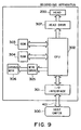
- FIG. 9 is a block diagram for an example of a liquid ejecting apparatus in accordance with the present invention.
- the recording apparatus receives printing data in the form of control signals from a host computer 300.
- the printing data are temporarily stored in an internal input/output interface 301 of the recording apparatus.
- they are converted into such data that are processable in the recording apparatus, and are inputted into the CPU 302 which doubles as a means for supplying head driving signals.
- the data inputted into the CPU 302 are processed by the CPU 302, based on the control program stored in a ROM 303, with the use of peripheral units such as a RAM 304; the data are converted into printable data (image data).
- the CPU 302 also creates driving data for driving the driving motor 305 which moves the recording sheet P and recording head 200 in synchronism with the image data.
- the image data and motor driving data are transmitted to the head 200 and driving motor 306 through a head driver 307 and a motor driver 305, and drive the heads 200 and driving motor 306, respectively, with controlled timings, creating an image.
- FIG. 10 is a schematic perspective view of the essential portion of a recording system as an example of a liquid ejecting apparatus in accordance with the present invention.
- the liquid ejecting head in this embodiment is a full-line head, and is equipped with four heads 201a - 201d correspondent to four colors, which are yellow (Y), magenta (M), cyan (C), and black (Bk).
- the four heads are fixedly supported in parallel to each other with a predetermined interval, being perpendicular to the recording medium conveyance direction, by a holder 202.
- Each head is enabled to cover the entire recordable range of a piece of recording medium 150, and comprises a plurality of ejection orifices disposed in the direction indicated by an arrow mark Y across the recordable range with an interval of 360 dpi.
- driving signals are supplied from a head driver 307 which constitutes a driving signal supplying means.
- a head driver 307 which constitutes a driving signal supplying means.
- four color inks Y, M, C and Bk as the liquids to be ejected are supplied from correspondent ink containers 204a - 204d.
- a referential character 206 designates a conveyer belt which constitutes a means for conveying various recording media described in the preceding embodiments of the present invention.
- the conveyer belt 206 is routed through a predetermined path by various rollers, and is driven by a driving roller controlled by a motor driver 305.
- the ink jet recording system in this embodiment comprises a pre-processing apparatus 251 and a post-processing apparatus 252.
- the pre-processing apparatus 251 is located on the upstream side of the recording medium conveyance path, and carries out various processes upon the recording medium before an actual recording process
- the post-processing apparatus 252 is located on the downstream side and carries out various post-processes upon the recording medium.
- the content of the pre-and post-processings varies depending upon the type of recording medium upon which recording is made, or ink type.
- the recording medium such as metal, plastic or ceramic is exposed to ultraviolet rays and ozone prior to recording to activate the surface of the recording medium so that ink adhesion to the recording medium is improved.
- an ionizing apparatus may be used to remove the static electricity from the recording medium prior to recording so that the dust is released from the recording medium.
- the fabric when fabric is used as the recording medium, the fabric may be treated with a substance selected from among an alkaline substance, a water soluble substance, a synthetic high polymer, water soluble metallic salt, urea, and thiourea prior to printing. The selection of pre-processings is not limited to those listed above. For example, a process for adjusting the recording medium temperature to a proper temperature for printing may be employed.
- the recording medium on which ink has been adhered may be thermally treated to fix the ink to the recording medium, or may be irradiated with ultraviolet rays to promote the fixation of the ink to the recording medium. Also, the processing agents which have been used in the pre-processing and remain inactivated in or on the recording medium are washed away.
- the present invention is such an invention that is applicable to a printer, as a peripheral image outputting apparatus for an information processing apparatus such as a computer, which records an image on a piece of recording medium by ejecting liquid in the form of a liquid droplet. It is also applicable to a copying machine integrated with a reader or the like, a facsimile machine with sending and receiving functions, an information processing apparatus, such as a word processor, equipped with a printing portion. Further, it is applicable to an industrial recording apparatus, or an industrial recording system, intricately integrated with various processing apparatuses.
- a term "recording” in this specification means “providing" a piece of recording medium with not only images, such as characters or graphics, which have specific meaning, but also meaningless patterns.
- the liquid to be ejected may be selected from among various substances such as ink which can be made to be in liquid form at least at the moment of ejection.
- ink which can be made to be in liquid form at least at the moment of ejection.
- it may be an ink which is in a solid state at the normal temperature but liquefies above a certain temperature. In other words, it does not matter whether a substance is in a solid state at the normal temperature or not, as long as it can be in a liquid state at the moment of ejection.
- recording medium the following may be listed: paper, thread, fiber, woven material, leather, metal, plastic (for example, OHP sheet, compact disc, ornamental plate, or the like), glass (for example, color filter, or the like), lumber, ceramic, or material with three dimensional network structure, for example, sponge.
Landscapes
- Physics & Mathematics (AREA)
- Geometry (AREA)
- Particle Formation And Scattering Control In Inkjet Printers (AREA)
- Ink Jet (AREA)
Applications Claiming Priority (4)
| Application Number | Priority Date | Filing Date | Title |
|---|---|---|---|
| JP11961598 | 1998-04-28 | ||
| JP11961498 | 1998-04-28 | ||
| JP11961598 | 1998-04-28 | ||
| JP11961498 | 1998-04-28 |
Publications (3)
| Publication Number | Publication Date |
|---|---|
| EP0953445A2 true EP0953445A2 (de) | 1999-11-03 |
| EP0953445A3 EP0953445A3 (de) | 2000-05-17 |
| EP0953445B1 EP0953445B1 (de) | 2005-03-09 |
Family
ID=26457304
Family Applications (1)
| Application Number | Title | Priority Date | Filing Date |
|---|---|---|---|
| EP99303259A Expired - Lifetime EP0953445B1 (de) | 1998-04-28 | 1999-04-27 | Flüssigkeitsausstossverfahren |
Country Status (3)
| Country | Link |
|---|---|
| US (1) | US6582060B1 (de) |
| EP (1) | EP0953445B1 (de) |
| DE (1) | DE69924047T2 (de) |
Cited By (4)
| Publication number | Priority date | Publication date | Assignee | Title |
|---|---|---|---|---|
| EP1287993A1 (de) * | 2001-09-04 | 2003-03-05 | Canon Kabushiki Kaisha | Bildaufzeichnungseinheit, -Vorrichtung und -Verfahren |
| EP1222938A3 (de) * | 2001-01-16 | 2003-07-09 | Hewlett-Packard Company | Thermischer Erzeugung der Tröpfchen für Aerosol |
| US6709805B1 (en) | 2003-04-24 | 2004-03-23 | Lexmark International, Inc. | Inkjet printhead nozzle plate |
| CN106733263A (zh) * | 2017-01-16 | 2017-05-31 | 西北农林科技大学 | 一种气泡充电电极静电喷头 |
Families Citing this family (11)
| Publication number | Priority date | Publication date | Assignee | Title |
|---|---|---|---|---|
| SG109494A1 (en) * | 2002-04-08 | 2005-03-30 | Inst Of High Performance Compu | Liquid ejection pump system |
| JP2004001490A (ja) * | 2002-04-23 | 2004-01-08 | Canon Inc | インクジェットヘッド |
| US7331650B2 (en) * | 2004-04-08 | 2008-02-19 | Eastman Kodak Company | Printhead having a removable nozzle plate |
| US7625073B2 (en) * | 2005-06-16 | 2009-12-01 | Canon Kabushiki Kaisha | Liquid discharge head and recording device |
| JP4713269B2 (ja) * | 2005-08-08 | 2011-06-29 | ソニー株式会社 | 液体吐出型記録ヘッドの製造方法 |
| US7857422B2 (en) * | 2007-01-25 | 2010-12-28 | Eastman Kodak Company | Dual feed liquid drop ejector |
| US8531952B2 (en) | 2009-11-30 | 2013-09-10 | The Hong Kong Polytechnic University | Method for measurement of network path capacity with minimum delay difference |
| US8567909B2 (en) | 2011-09-09 | 2013-10-29 | Eastman Kodak Company | Printhead for inkjet printing device |
| US8840981B2 (en) | 2011-09-09 | 2014-09-23 | Eastman Kodak Company | Microfluidic device with multilayer coating |
| JP6095315B2 (ja) * | 2012-10-02 | 2017-03-15 | キヤノン株式会社 | 液体吐出ヘッドの製造方法 |
| US10286661B2 (en) * | 2016-10-27 | 2019-05-14 | Canon Kabushiki Kaisha | Liquid discharge method and liquid discharge apparatus for heating a liquid through a surface to generate a bubble |
Citations (1)
| Publication number | Priority date | Publication date | Assignee | Title |
|---|---|---|---|---|
| JPH0410941A (ja) | 1990-04-27 | 1992-01-16 | Canon Inc | 液滴噴射方法及び該方法を用いた記録装置 |
Family Cites Families (7)
| Publication number | Priority date | Publication date | Assignee | Title |
|---|---|---|---|---|
| JPH0625194B2 (ja) | 1984-01-30 | 1994-04-06 | ダイセル化学工業株式会社 | 新規なエポキシ樹脂の製造方法 |
| JPH0725864B2 (ja) | 1987-03-09 | 1995-03-22 | ダイセル化学工業株式会社 | エポキシ樹脂 |
| JP2736664B2 (ja) | 1988-11-24 | 1998-04-02 | 三共化成株式会社 | 射出成形品の製法 |
| DE69126996T2 (de) * | 1990-04-27 | 1998-02-19 | Canon Kk | Aufzeichnungsverfahren und -gerät |
| JP3179834B2 (ja) | 1991-07-19 | 2001-06-25 | 株式会社リコー | 液体飛翔記録装置 |
| US5621447A (en) * | 1991-10-25 | 1997-04-15 | Canon Kabushiki Kaisha | Jet recording method |
| DE19505465A1 (de) * | 1994-02-18 | 1995-08-24 | Hitachi Koki Kk | Thermischer Tintenstrahldrucker |
-
1999
- 1999-04-27 DE DE69924047T patent/DE69924047T2/de not_active Expired - Lifetime
- 1999-04-27 EP EP99303259A patent/EP0953445B1/de not_active Expired - Lifetime
- 1999-04-28 US US09/300,791 patent/US6582060B1/en not_active Expired - Lifetime
Patent Citations (1)
| Publication number | Priority date | Publication date | Assignee | Title |
|---|---|---|---|---|
| JPH0410941A (ja) | 1990-04-27 | 1992-01-16 | Canon Inc | 液滴噴射方法及び該方法を用いた記録装置 |
Cited By (8)
| Publication number | Priority date | Publication date | Assignee | Title |
|---|---|---|---|---|
| EP1222938A3 (de) * | 2001-01-16 | 2003-07-09 | Hewlett-Packard Company | Thermischer Erzeugung der Tröpfchen für Aerosol |
| SG109485A1 (en) * | 2001-01-16 | 2005-03-30 | Hewlett Packard Co | Thermal generation of droplets for aerosol |
| US7594507B2 (en) | 2001-01-16 | 2009-09-29 | Hewlett-Packard Development Company, L.P. | Thermal generation of droplets for aerosol |
| EP1287993A1 (de) * | 2001-09-04 | 2003-03-05 | Canon Kabushiki Kaisha | Bildaufzeichnungseinheit, -Vorrichtung und -Verfahren |
| US6749290B2 (en) | 2001-09-04 | 2004-06-15 | Canon Kabushiki Kaisha | Recording unit, image recording apparatus and image recording method |
| KR100495295B1 (ko) * | 2001-09-04 | 2005-06-14 | 캐논 가부시끼가이샤 | 기록 유니트, 화상 기록 장치 및 화상 기록 방법 |
| US6709805B1 (en) | 2003-04-24 | 2004-03-23 | Lexmark International, Inc. | Inkjet printhead nozzle plate |
| CN106733263A (zh) * | 2017-01-16 | 2017-05-31 | 西北农林科技大学 | 一种气泡充电电极静电喷头 |
Also Published As
| Publication number | Publication date |
|---|---|
| EP0953445B1 (de) | 2005-03-09 |
| DE69924047D1 (de) | 2005-04-14 |
| US6582060B1 (en) | 2003-06-24 |
| EP0953445A3 (de) | 2000-05-17 |
| DE69924047T2 (de) | 2006-02-02 |
Similar Documents
| Publication | Publication Date | Title |
|---|---|---|
| US6612688B2 (en) | Liquid ejection method | |
| AU712741B2 (en) | Liquid ejecting head, liquid ejecting device and liquid ejecting method | |
| EP0953445B1 (de) | Flüssigkeitsausstossverfahren | |
| US6378205B1 (en) | Method for producing liquid ejecting head and liquid ejecting head obtained by the same method | |
| JP4846028B2 (ja) | インクジェット記録ヘッド | |
| US6435669B1 (en) | Liquid ejecting head, liquid ejecting device and liquid ejecting method | |
| US6663230B2 (en) | Liquid ejection head, apparatus and recovery method for them | |
| US6447103B1 (en) | Liquid ejecting method, liquid ejecting head, head cartridge and liquid ejecting apparatus using same | |
| US6527376B1 (en) | Liquid-ejecting head, liquid-ejecting method and liquid-ejecting printing apparatus | |
| US6183068B1 (en) | Liquid discharging head, head cartridge, liquid discharging device, recording system, head kit, and fabrication process of liquid discharging head | |
| JPH0911471A (ja) | 液体吐出方法、液体吐出ヘッド、ヘッドカートリッジ、液体吐出装置、及び液体吐出ヘッドキット | |
| US9139005B2 (en) | Liquid ejection head and process for producing the same | |
| JP2002154208A (ja) | インクジェット記録ヘッドおよび記録装置 | |
| JP3563999B2 (ja) | 液体吐出方法,液体吐出ヘッドおよび液体吐出装置 | |
| JP2009119725A (ja) | インクジェット記録ヘッド及びインクジェット記録ヘッドの製造方法 | |
| JP2001010056A (ja) | 液体吐出ヘッド、液体吐出方法、および液体吐出記録装置 | |
| AU2003204459B2 (en) | Liquid Ejection Method | |
| JP4856827B2 (ja) | インクジェット記録ヘッドの製造方法、インクジェット記録ヘッド、およびインクジェット記録方法 |
Legal Events
| Date | Code | Title | Description |
|---|---|---|---|
| PUAI | Public reference made under article 153(3) epc to a published international application that has entered the european phase |
Free format text: ORIGINAL CODE: 0009012 |
|
| AK | Designated contracting states |
Kind code of ref document: A2 Designated state(s): DE ES FR GB IT NL |
|
| AX | Request for extension of the european patent |
Free format text: AL;LT;LV;MK;RO;SI |
|
| PUAL | Search report despatched |
Free format text: ORIGINAL CODE: 0009013 |
|
| AK | Designated contracting states |
Kind code of ref document: A3 Designated state(s): AT BE CH CY DE DK ES FI FR GB GR IE IT LI LU MC NL PT SE |
|
| AX | Request for extension of the european patent |
Free format text: AL;LT;LV;MK;RO;SI |
|
| 17P | Request for examination filed |
Effective date: 20001009 |
|
| AKX | Designation fees paid |
Free format text: DE ES FR GB IT NL |
|
| 17Q | First examination report despatched |
Effective date: 20030724 |
|
| GRAP | Despatch of communication of intention to grant a patent |
Free format text: ORIGINAL CODE: EPIDOSNIGR1 |
|
| RTI1 | Title (correction) |
Free format text: LIQUID EJECTION METHOD |
|
| GRAS | Grant fee paid |
Free format text: ORIGINAL CODE: EPIDOSNIGR3 |
|
| GRAA | (expected) grant |
Free format text: ORIGINAL CODE: 0009210 |
|
| AK | Designated contracting states |
Kind code of ref document: B1 Designated state(s): DE ES FR GB IT NL |
|
| PG25 | Lapsed in a contracting state [announced via postgrant information from national office to epo] |
Ref country code: NL Free format text: LAPSE BECAUSE OF FAILURE TO SUBMIT A TRANSLATION OF THE DESCRIPTION OR TO PAY THE FEE WITHIN THE PRESCRIBED TIME-LIMIT Effective date: 20050309 |
|
| REG | Reference to a national code |
Ref country code: GB Ref legal event code: FG4D |
|
| REF | Corresponds to: |
Ref document number: 69924047 Country of ref document: DE Date of ref document: 20050414 Kind code of ref document: P |
|
| PG25 | Lapsed in a contracting state [announced via postgrant information from national office to epo] |
Ref country code: ES Free format text: LAPSE BECAUSE OF FAILURE TO SUBMIT A TRANSLATION OF THE DESCRIPTION OR TO PAY THE FEE WITHIN THE PRESCRIBED TIME-LIMIT Effective date: 20050620 |
|
| NLV1 | Nl: lapsed or annulled due to failure to fulfill the requirements of art. 29p and 29m of the patents act | ||
| PLBE | No opposition filed within time limit |
Free format text: ORIGINAL CODE: 0009261 |
|
| STAA | Information on the status of an ep patent application or granted ep patent |
Free format text: STATUS: NO OPPOSITION FILED WITHIN TIME LIMIT |
|
| ET | Fr: translation filed | ||
| 26N | No opposition filed |
Effective date: 20051212 |
|
| PGFP | Annual fee paid to national office [announced via postgrant information from national office to epo] |
Ref country code: IT Payment date: 20140402 Year of fee payment: 16 Ref country code: FR Payment date: 20140428 Year of fee payment: 16 |
|
| PG25 | Lapsed in a contracting state [announced via postgrant information from national office to epo] |
Ref country code: IT Free format text: LAPSE BECAUSE OF NON-PAYMENT OF DUE FEES Effective date: 20150427 |
|
| REG | Reference to a national code |
Ref country code: FR Ref legal event code: ST Effective date: 20151231 |
|
| PG25 | Lapsed in a contracting state [announced via postgrant information from national office to epo] |
Ref country code: FR Free format text: LAPSE BECAUSE OF NON-PAYMENT OF DUE FEES Effective date: 20150430 |
|
| PGFP | Annual fee paid to national office [announced via postgrant information from national office to epo] |
Ref country code: GB Payment date: 20160427 Year of fee payment: 18 Ref country code: DE Payment date: 20160430 Year of fee payment: 18 |
|
| REG | Reference to a national code |
Ref country code: DE Ref legal event code: R119 Ref document number: 69924047 Country of ref document: DE |
|
| GBPC | Gb: european patent ceased through non-payment of renewal fee |
Effective date: 20170427 |
|
| PG25 | Lapsed in a contracting state [announced via postgrant information from national office to epo] |
Ref country code: DE Free format text: LAPSE BECAUSE OF NON-PAYMENT OF DUE FEES Effective date: 20171103 |
|
| PG25 | Lapsed in a contracting state [announced via postgrant information from national office to epo] |
Ref country code: GB Free format text: LAPSE BECAUSE OF NON-PAYMENT OF DUE FEES Effective date: 20170427 |