EP0953471A2 - Commande d'amortissement de transmission pour un véhicule électrique - Google Patents
Commande d'amortissement de transmission pour un véhicule électrique Download PDFInfo
- Publication number
- EP0953471A2 EP0953471A2 EP99108276A EP99108276A EP0953471A2 EP 0953471 A2 EP0953471 A2 EP 0953471A2 EP 99108276 A EP99108276 A EP 99108276A EP 99108276 A EP99108276 A EP 99108276A EP 0953471 A2 EP0953471 A2 EP 0953471A2
- Authority
- EP
- European Patent Office
- Prior art keywords
- motor
- signals
- input port
- torque
- coupled
- Prior art date
- Legal status (The legal status is an assumption and is not a legal conclusion. Google has not performed a legal analysis and makes no representation as to the accuracy of the status listed.)
- Granted
Links
Images


Classifications
-
- B—PERFORMING OPERATIONS; TRANSPORTING
- B60—VEHICLES IN GENERAL
- B60L—PROPULSION OF ELECTRICALLY-PROPELLED VEHICLES; SUPPLYING ELECTRIC POWER FOR AUXILIARY EQUIPMENT OF ELECTRICALLY-PROPELLED VEHICLES; ELECTRODYNAMIC BRAKE SYSTEMS FOR VEHICLES IN GENERAL; MAGNETIC SUSPENSION OR LEVITATION FOR VEHICLES; MONITORING OPERATING VARIABLES OF ELECTRICALLY-PROPELLED VEHICLES; ELECTRIC SAFETY DEVICES FOR ELECTRICALLY-PROPELLED VEHICLES
- B60L15/00—Methods, circuits, or devices for controlling the traction-motor speed of electrically-propelled vehicles
- B60L15/20—Methods, circuits, or devices for controlling the traction-motor speed of electrically-propelled vehicles for control of the vehicle or its driving motor to achieve a desired performance, e.g. speed, torque, programmed variation of speed
-
- B—PERFORMING OPERATIONS; TRANSPORTING
- B60—VEHICLES IN GENERAL
- B60L—PROPULSION OF ELECTRICALLY-PROPELLED VEHICLES; SUPPLYING ELECTRIC POWER FOR AUXILIARY EQUIPMENT OF ELECTRICALLY-PROPELLED VEHICLES; ELECTRODYNAMIC BRAKE SYSTEMS FOR VEHICLES IN GENERAL; MAGNETIC SUSPENSION OR LEVITATION FOR VEHICLES; MONITORING OPERATING VARIABLES OF ELECTRICALLY-PROPELLED VEHICLES; ELECTRIC SAFETY DEVICES FOR ELECTRICALLY-PROPELLED VEHICLES
- B60L50/00—Electric propulsion with power supplied within the vehicle
- B60L50/50—Electric propulsion with power supplied within the vehicle using propulsion power supplied by batteries or fuel cells
- B60L50/51—Electric propulsion with power supplied within the vehicle using propulsion power supplied by batteries or fuel cells characterised by AC-motors
-
- Y—GENERAL TAGGING OF NEW TECHNOLOGICAL DEVELOPMENTS; GENERAL TAGGING OF CROSS-SECTIONAL TECHNOLOGIES SPANNING OVER SEVERAL SECTIONS OF THE IPC; TECHNICAL SUBJECTS COVERED BY FORMER USPC CROSS-REFERENCE ART COLLECTIONS [XRACs] AND DIGESTS
- Y02—TECHNOLOGIES OR APPLICATIONS FOR MITIGATION OR ADAPTATION AGAINST CLIMATE CHANGE
- Y02T—CLIMATE CHANGE MITIGATION TECHNOLOGIES RELATED TO TRANSPORTATION
- Y02T10/00—Road transport of goods or passengers
- Y02T10/60—Other road transportation technologies with climate change mitigation effect
- Y02T10/64—Electric machine technologies in electromobility
-
- Y—GENERAL TAGGING OF NEW TECHNOLOGICAL DEVELOPMENTS; GENERAL TAGGING OF CROSS-SECTIONAL TECHNOLOGIES SPANNING OVER SEVERAL SECTIONS OF THE IPC; TECHNICAL SUBJECTS COVERED BY FORMER USPC CROSS-REFERENCE ART COLLECTIONS [XRACs] AND DIGESTS
- Y02—TECHNOLOGIES OR APPLICATIONS FOR MITIGATION OR ADAPTATION AGAINST CLIMATE CHANGE
- Y02T—CLIMATE CHANGE MITIGATION TECHNOLOGIES RELATED TO TRANSPORTATION
- Y02T10/00—Road transport of goods or passengers
- Y02T10/60—Other road transportation technologies with climate change mitigation effect
- Y02T10/70—Energy storage systems for electromobility, e.g. batteries
-
- Y—GENERAL TAGGING OF NEW TECHNOLOGICAL DEVELOPMENTS; GENERAL TAGGING OF CROSS-SECTIONAL TECHNOLOGIES SPANNING OVER SEVERAL SECTIONS OF THE IPC; TECHNICAL SUBJECTS COVERED BY FORMER USPC CROSS-REFERENCE ART COLLECTIONS [XRACs] AND DIGESTS
- Y02—TECHNOLOGIES OR APPLICATIONS FOR MITIGATION OR ADAPTATION AGAINST CLIMATE CHANGE
- Y02T—CLIMATE CHANGE MITIGATION TECHNOLOGIES RELATED TO TRANSPORTATION
- Y02T10/00—Road transport of goods or passengers
- Y02T10/60—Other road transportation technologies with climate change mitigation effect
- Y02T10/72—Electric energy management in electromobility
Definitions
- This invention relates to electrically driven vehicles, and more particularly to such vehicles in which an axle shaft connects the electric motor to a drive wheel.
- Electric vehicles are coming into increasing importance because of their supposedly low environmental impact.
- a heavyweight vehicle such as a truck or bus is fitted with an electric drivetrain driving the drive wheels through a speed reducing differential and one or more axles
- acceleration from low speeds is not smooth.
- Analysis of the perturbations in acceleration have shown that the stiffness of the axle shafts which couple torque to the drive wheels is such that the axle tends to twist, which, in conjunction with the very low friction of the electric drive train, results in oscillations of the vehicle speed.
- a motor vehicle includes a source of electric energy, and an electric motor including an output shaft.
- the vehicle also includes a control which is a source of operator-controlled commanded torque signals.
- a control system is coupled to the source of electric energy, to the electric motor, and to receive torque command signals, for controlling the motor to produce the commanded torque at the output shaft of the motor.
- the vehicle further includes a mechanical gearbox including an input shaft coupled to the shaft of the motor and also includes an output shaft. The gearbox reduces the input shaft speed to produce a lower output shaft speed, with a concomitant increase in the output shaft torque.
- a drive wheel supports and drives the vehicle.
- An elongated axle shaft is coupled to the drive wheel and to the output shaft of the gearbox, for thereby coupling torque to the drive wheel from the gearbox.
- the axle shaft has a stiffness which, in conjunction with the mass of the vehicle, tends to produce undesired jerky motion of the vehicle.
- a motor speed sensor produces signals representative of the speed of the motor.
- a differencing arrangement includes a noninverting input port coupled to the source of operator-controlled commanded torque signals, and also includes an inverting input port, for subtracting signals applied to the inverting input port of the differencing arrangement from the commanded torque signals, for generating the torque command signals.
- a damping signal generator is coupled to the motor speed sensor and to the inverting input port of the differencing arrangement, for coupling to the inverting input port of the differencing arrangement at least the low-frequency components of motor acceleration.
- the gearbox is a differential including a second output shaft
- the vehicle further comprises a second drive wheel, and a second axle coupling the second drive wheel to the second output shaft of the differential.
- the damping signal generator may include an infinite-impulse-response transversal filter including an input port coupled to the motor speed sensor, for receiving the motor speed signals, for generating the damping signals.
- the infinite-impulse-response filter may include a delay stage including an input node coupled to receive the motor speed signals, and also including an output port at which delayed motor speed signals appear.
- a first summing circuit including an inverting input port and a noninverting input port, and an output port at which the difference between the signals applied to the inverting and noninverting input ports is generated.
- a second summing circuit includes an inverting input port, and also includes a noninverting input port coupled to the output port of the first summing circuit. The second summing circuit further includes an output port at which the damping signals are generated.
- a first multiplier is coupled to the input node of the delay stage and to the noninverting input port of the first summing circuit, for coupling the motor speed signals from the node to the noninverting input port of the first summing circuit with a particular gain.
- a second multiplier is coupled to the output port of the delay stage and to the inverting input port of the second summing circuit, for coupling the delayed motor speed signals from the output port of the delay stage to the inverting input port of the second summing circuit with a second gain.
- the second gain may equal the particular gain.
- a feedback path is coupled to the output port of the second summing circuit and to the inverting input port of the first summing circuit.
- the feedback path includes a delay stage and a third multiplier for multiplying feedback signals traversing the feedback path by a third gain.
- a vehicle 10 includes a pair of drive wheels 12l, 12r, which are attached to axle shafts 14l, 14r.
- Axle shafts 14 are connected to shafts of a speed-reducing differential 16, which receives torque from the output shaft 18s of an electric motor 18.
- Motor 18 receives electrical drive from a controller illustrated as a box 20, which includes a control system.
- Controller 20 receives electrical power from a battery 22, and produces control signals for the motor in response to command torque signals produced by an operator control, illustrated as a box 24.
- vehicle 10 is also illustrated as having front wheels 26l, 26r.
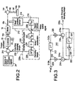
- FIGURE 2 is a simplified block diagram of a vehicle according to an aspect of the invention.
- the signals representing the desired torque which are generated by operator control 24 are applied to the noninverting input port of a differencing or error signal generating circuit.
- Differencing circuit 24 also includes an inverting input port.
- Differencing circuit 24 subtracts low-frequency components of the damping torque signal applied to its inverting input port from the commanded torque signals applied to its noninverting input port, to thereby generate torque command signals for application to controller 20.
- Controller 20 processes the torque command signals applied thereto in accordance with its control laws, and produces controlled electrical power, which is applied to the electrical input ports 18p of motor 18. Motor 18 produces the commanded torque.
- the stiffness of the axle shafts in the low-friction environment of electric drive, results in unwanted low-rate variations in vehicle speed.
- the motor speed is sensed, and a damping torque signal generator generates damping torque signals which are summed with the commanded torque signals, to thereby generate corrected torque command signals which counter the effects of the unwanted variations in speed.
- a motor speed signal generator 212 in FIGURE 2 includes a shaft position sensor 214 and a differentiator 216, which differentiates the shaft position signals from position sensor 214, to thereby generate motor speed signals.
- the motor speed signals are applied from motor speed sensor 212 to a damping torque signal generator 220, which produces low-frequency components of damping torque signals on a signal path 228, and applies the signals to the inverting input port of differencing circuit 210.
- a differentiator 222 differentiates the motor speed signals from speed sensor block 212, to produce signals related to the motor acceleration.
- the motor acceleration signals are applied to a gain block 224, where they are multiplied by a constant G to produce damping torque related signals.
- the damping torque related signals are limited in a low-pass filter 226 to a low frequency, which, for example, may be less than ten Hertz, to produce the low-frequency components of the damping torque on signal path 228.
- the low-frequency damping torque signals when subtracted from the commanded torque, produce torque command signals which, when modified by the control laws of controller 20, command the motor with a varying torque which offsets the torque variations caused by the resonant elements including the axle shafts 14l and 14r.
- axle shaft 14l is illustrated in FIGURE 2 as 14li, and is coupled to one of the shafts (not separately illustrated) of differential 16.
- the outboard end of axle shaft 14l is adjacent drive wheel 12l, and is designated 14lo.
- FIGURE 3 is a simplified block diagram of an implementation of damping circuit 220 of FIGURE 2.
- the motor rotational speed signal rot is applied to the input port 220i of the damping circuit 220, from which it is applied to an input node 312N of an infinite-impulse response (IIR) transversal filter designated generally as 310.
- Filter 310 of FIGURE 3 includes a one-clock-cycle delay or Z -1 element 312, which receives the motor rotational speed signal rot from node 312N, and delays it, to thereby produce delayed motor rotational speed signal rot at its output port 312o.
- a first summing circuit 314 has both inverting and noninverting input ports, and also includes a sum or output port which is coupled to the noninverting input port of a second summing circuit 316.
- a first multiplier or gain element 318 multiplies the motor rotational speed signal rot from node 312N by a predetermined value, represented as the value "a,” and applies the multiplied signal to the noninverting input port of first summing circuit 314.
- First summing circuit 314 subtracts the value of signal applied to its inverting input port from the value of the multiplied signal applied to the noninverting input port, and couples the resulting output signal to the noninverting input port of second summing circuit 316.
- the delayed motor rotational speed signal rot at output port 312o of delay element 312 is multiplied by a second multiplier or gain element 320 by a predetermined value, which in this example is the same value "a".
- the delayed and multiplied signal appearing at the output port of multiplier or gain element 320 is applied to the inverting input port of summing circuit 316.
- summing circuit 316 subtracts the value of the signal applied to its inverting input port from the value applied to its noninverting input port.
- the resulting difference signal appears at output port 316o, and corresponds to the low frequency components of the damping torque signal which are applied by damping signal generator 220 to path 228 of FIGURE 2.
- a feedback signal path designated generally as 322 is coupled between output port 316o of summing circuit 316 and the inverting input port of summing circuit 314.
- Feedback signal path 322 includes a unit delay element 324 cascaded with a multiplier or gain element 326, which multiplies the delayed signal by a value, designated as "b" in FIGURE 3.
- the structure represented by FIGURE 3 corresponds to the software which implements one embodiment of the invention.
- FIGURE 4 is a simplified block diagram expressing the characteristics of the various parts of the vehicle, and their interrelationship.
- the commanded torque signals from source 20 are applied through differencing circuit 210 to the electric vehicle drive train 20, which includes the controller and the motor.
- the drive train 20 produces, on a path illustrated as 410, mechanical torque T em representing the electric motor torque.
- the difference between the motor torque and the load torque T load is produced by means of the differencing block designated 412, and the difference appearing on signal path 411 represents the torque applied at the motor output shaft.
- the motor shaft speed ⁇ rot resulting from the net torque at the motor shaft is determined by 1/Js, where J represents the inertia of the rotor of the motor and the motor shaft, and 1/s represents integration.
- the rotational speed ⁇ rot of the motor shaft is applied to a block 416, representing the gear step-down ratio GR of the differential 16 of FIGURE 1, which reduces the rotational speed or rate from ⁇ rot to ⁇ axi at the inboard end 14li of the axle 14l.
- the rotation of the inboard end 14li of axle shaft 14l does not, because of the lack of stiffness of the axle shaft, result in immediate rotation of the outboard end of the shaft.
- the difference, generated by differencing block 417, between the rotational speed of the inboard end 14li of the axle shaft ( ⁇ axi ) and the rotational speed of the outboard end of the axle (the wheel speed ⁇ wh ) results in a change in the twist angle ⁇ tw of the axle at the output of a block 418 representing integration.
- the twist angle ⁇ tw when multiplied in block 420 by the stiffness K of the axle shaft, results in a torque T ax at both ends of the axle shaft 14l.
- the axle torque T ax becomes a linear force F ax when multiplied in a block 422 by a factor 1/R wheel related to the radius of the drive wheel 12l.
- the linear force F ax when multiplied in block 424 by a factor 1/Ms, where M is the mass of the vehicle, and 1/s is an integration, results in vehicle speed V vehicle .
- the velocity V vehicle of the vehicle as represented in FIGURE 4 at the output of block 424, when multiplied by a factor 1/R wheel in feedback block 426, produces the rotational wheel speed ⁇ wh which is subtracted from the inboard axle speed in differencing block 417.
- axle torque T ax appearing at the output of block 420 of FIGURE 4 is transformed through the gearing of the differential 16 to produce a transformed torque T load , which is fed back to summer 412 for subtraction from the motor torque.
- the oscillation toward the reduction of which the invention is directed, arises from the loop 430 of FIGURE 4, including blocks 417, 318, 420, 422, 424, and 426.
- Friction is not modeled in FIGURE 4, because its value is so low in the electric power train, at least in part because of the lack of the moving crankshaft, pistons, and the like of an internal combustion engine, and more notably because of lack of a shiftable transmission, which is a major contributor to friction, and therefore to damping.
- lack of a shiftable transmission may make unstable a drive train which would be stable in the presence of such a transmission.
- Friction B were it large enough to model in FIGURE 4, would be represented as a phantom-line block 432 connecting the output of block 414 to a further inverting input port of differencing block 412.
- the improvement provided by the damping torque signal generator 220 or FIGURES 2 and 4 functions by sampling the rotational speed rot at the output of the motor, and feeding back to the inverting input port of block 210 a component of motor acceleration which, when transformed through the electric vehicle drive train 20 to path 410, provides a damping signal which would be provided by block 432, were there enough friction to provide damping. More particularly, the derivative block 222 artificially provides equivalent inertia J.
- the oscillatory variation in speed affects the values of all the variables in loop 430 of FIGURE 4.
- the oscillation tends to vary the value of axle torque T ax .
- This variation in axle torque is coupled through block 428. If at a particular moment the varying value of axle torque is increasing, the load torque T load at summing point 412 also increases. Summing point 412 subtracts the increasing value of axle torque from the electric motor torque T em , to produce a decreasing value of torque at the output of summing point 412. This decreasing value of torque at the output of summing point 412 flows through the inertia of the rotor and rotor shaft represented by block 414, to produce a decreasing value of rotational speed axi .
- the decreasing value of rotational speed returns by way of block 416 to loop 430 to maintain the oscillation, and is also coupled to differentiator 222 of damping signal generator 220.
- the differentiator generates a negative signal from the decreasing shaft speed rotor .
- the negative signal from differentiator 222 is amplified and low-pass-filtered, which do not affect the sign of the signal.
- the negative damping signal is applied from LPF 226 to summing circuit 210, where the negative value is subtracted from the commanded torque. Subtraction of a negative value increases the commanded torque at the output of summing circuit 210.
- the increased commanded torque flows through the drive train represented by block 20, and appears as an increased motor torque on path 410.
- the increased motor torque on path 410 when with the increasing load torque, results in a substantially constant value of net torque at the input of block 414, notwithstanding the oscillatory nature of loop 430.
- the breaking of the variation of feedback due to the oscillation stabilizes the entire vehicle control system.
- control system may be implemented as hardware, firmware, or software, but software is preferred where possible.
- a motor vehicle (10) includes a source (22) of electric energy, and an electric motor (18) including an output shaft (18s).
- the vehicle (10) also includes a control which is a source (24) of operator-controlled commanded torque signals.
- a control system (20) is coupled to the source (22) of electric energy, to the electric motor (18), and to receive torque command signals, for controlling the motor (18) to produce the commanded torque at the output shaft of the motor (18).
- the vehicle (10) further includes a mechanical gearbox (16) including an input shaft coupled to the shaft (18s) of the motor (18) and also includes an output shaft. The gearbox reduces the input shaft speed to produce a lower output shaft speed, with a concomitant increase in the output shaft torque.
- a drive wheel (12l) supports and drives the vehicle (10).
- An elongated axle shaft (14l, 14r) is coupled to the drive wheel (12l, 12r) and to the output shaft of the gearbox (16), for thereby coupling torque to the drive wheel (12l, 12r) from the gearbox (16).
- the axle shaft has a stiffness which, in conjunction with the mass of the vehicle (10), tends to produce undesired jerky motion of the vehicle (10).
- a motor (18) speed sensor produces signals representative of the speed of the motor (18).
- a differencing arrangement (210) includes a noninverting (+) input port coupled to the source (24) of operator-controlled commanded torque signals, and also includes an inverting (-) input port, for subtracting signals applied to the inverting (-) input port of the differencing arrangement (210) from the commanded torque signals, for generating the torque command signals.
- a damping signal generator (220) is coupled to the motor (18) speed sensor (212) and to the inverting (-) input port of the differencing arrangement (210), for coupling to the inverting (-) input port of the differencing arrangement (210) at least the low-frequency components of motor (18) acceleration.
- the gearbox (16) is a differential (16) including a second output shaft
- the vehicle (10) further comprises a second drive wheel (12r), and a second axle (14r) coupling the second drive wheel (12r) to the second output shaft of the differential (16).
- the damping signal generator (220) may include an infinite-impulse-response (IIR) transversal filter (310) including an input port (220i) coupled to the motor (18) speed sensor (212), for receiving the motor (18) speed signals, for generating the damping signals.
- IIR infinite-impulse-response
- the infinite-impulse-response filter (310) may include a delay stage (312) including an input node (312N) coupled to receive the motor (18) speed signals, and also including an output port (312o) at which delayed motor (18) speed signals appear.
- a first summing circuit (314) including an inverting (-) input port and a noninverting (+) input port, and an output port (314o) at which the difference between the signals applied to the inverting and noninverting input ports is generated.
- a second summing circuit (316) includes an inverting (-) input port, and also includes a noninverting (+) input port coupled to the output port (314o) of the first summing circuit (314).
- the second summing circuit (316) further includes an output port (316o) at which the damping signals are generated.
- a first multiplier (318) is coupled to the input node (312N) of the delay stage (312) and to the noninverting (+) input port of the first summing circuit (314), for coupling the motor (18) speed signals from the node (312N) to the noninverting (+) input port of the first summing circuit (314) with a particular gain (a).
- a second multiplier (320) is coupled to the output port (312o) of the delay stage (312) and to the inverting (-) input port of the second summing circuit (316), for coupling the delayed motor (18) speed signals from the output port (312o) of the delay stage (312) to the inverting (-) input port of the second summing circuit (316) with a second gain (a).
- the second gain may equal the particular gain.
- a feedback path (322) is coupled to the output port (316o) of the second summing circuit (316) and to the inverting (-) input port of the first summing circuit (314).
- the feedback path (322) includes a delay stage (324) and a third multiplier (326) for multiplying feedback signals traversing the feedback path (322) by a third gain (b).
Landscapes
- Engineering & Computer Science (AREA)
- Power Engineering (AREA)
- Transportation (AREA)
- Mechanical Engineering (AREA)
- Life Sciences & Earth Sciences (AREA)
- Sustainable Development (AREA)
- Sustainable Energy (AREA)
- Electric Propulsion And Braking For Vehicles (AREA)
- Arrangement Of Transmissions (AREA)
Applications Claiming Priority (4)
| Application Number | Priority Date | Filing Date | Title |
|---|---|---|---|
| US8339798P | 1998-04-29 | 1998-04-29 | |
| US83397P | 1998-04-29 | ||
| US80148 | 1998-05-18 | ||
| US09/080,148 US6196345B1 (en) | 1998-05-18 | 1998-05-18 | Drive-line damping control for an electric vehicle |
Publications (3)
| Publication Number | Publication Date |
|---|---|
| EP0953471A2 true EP0953471A2 (fr) | 1999-11-03 |
| EP0953471A3 EP0953471A3 (fr) | 2001-10-17 |
| EP0953471B1 EP0953471B1 (fr) | 2010-10-13 |
Family
ID=26763134
Family Applications (1)
| Application Number | Title | Priority Date | Filing Date |
|---|---|---|---|
| EP99108276A Expired - Lifetime EP0953471B1 (fr) | 1998-04-29 | 1999-04-27 | Commande d'amortissement de transmission pour un véhicule électrique |
Country Status (9)
| Country | Link |
|---|---|
| EP (1) | EP0953471B1 (fr) |
| JP (1) | JP4659935B2 (fr) |
| KR (1) | KR100567042B1 (fr) |
| CN (1) | CN1168621C (fr) |
| AR (1) | AR016237A1 (fr) |
| BR (1) | BR9901305A (fr) |
| CA (1) | CA2269562C (fr) |
| DE (1) | DE69942847D1 (fr) |
| TW (1) | TW519527B (fr) |
Cited By (6)
| Publication number | Priority date | Publication date | Assignee | Title |
|---|---|---|---|---|
| US7197390B2 (en) * | 2003-03-13 | 2007-03-27 | Wavecrest Laboratories Llc | Electric vehicle with adaptive cruise control system |
| CN101746415B (zh) * | 2008-12-18 | 2011-06-01 | 匡斌 | 一种电动车的电子差速控制系统 |
| GB2490493A (en) * | 2011-04-28 | 2012-11-07 | Sevcon Ltd | Torque control apparatus for electric vehicle |
| US9654032B2 (en) | 2011-04-28 | 2017-05-16 | Sevcon Limited | Electric motor and motor controller |
| EP3110657A4 (fr) * | 2014-02-28 | 2018-02-21 | BAE Systems Controls Inc. | Filtre de kalman double pour amortissement de torsion d'entraînements de traction électrique |
| CN111038237A (zh) * | 2019-12-13 | 2020-04-21 | 丁钰松 | 一种省电的电动汽车动力装置 |
Families Citing this family (6)
| Publication number | Priority date | Publication date | Assignee | Title |
|---|---|---|---|---|
| CN1318773C (zh) * | 2001-08-24 | 2007-05-30 | 卢克摩擦片和离合器两合公司 | 具有振动阻尼调节的动力传动系统 |
| DE102005034794A1 (de) * | 2004-07-23 | 2006-02-23 | Ford Global Technologies, LLC, Dearborn | Verfahren zum Dämpfen von Vibrationen im Antriebsstrang eines hybridelektrischen Fahrzeugs |
| JP5455802B2 (ja) * | 2010-06-11 | 2014-03-26 | 日立建機株式会社 | 電動車両のピッチング制御装置 |
| CN102975625B (zh) * | 2012-11-12 | 2015-10-28 | 奇瑞汽车股份有限公司 | 一种电动车增程器调速的实现方法 |
| CN104179963B (zh) * | 2013-05-23 | 2017-06-13 | 大陆汽车投资(上海)有限公司 | 选/换档机构的控制方法和变速器控制单元 |
| JP6167363B2 (ja) * | 2013-09-12 | 2017-07-26 | 日立オートモティブシステムズ株式会社 | 電動車両の制御装置及び電動車両の制御方法 |
Family Cites Families (9)
| Publication number | Priority date | Publication date | Assignee | Title |
|---|---|---|---|---|
| GB2181008B (en) * | 1985-09-25 | 1989-09-20 | Sony Corp | Infinite impulse response filters |
| US4766967A (en) * | 1985-12-27 | 1988-08-30 | Eaton Corporation | Oscillation control system for electric motor drive |
| JPS6474005A (en) * | 1987-09-12 | 1989-03-20 | Toyota Motor Corp | Oscillation-proof controlling method for electric automobile |
| JP2884942B2 (ja) * | 1992-09-17 | 1999-04-19 | 株式会社日立製作所 | 電気車制御装置 |
| JP3227000B2 (ja) * | 1993-01-21 | 2001-11-12 | 株式会社日立製作所 | モータの速度制御装置 |
| US5349278A (en) * | 1993-05-13 | 1994-09-20 | Hughes Aircraft Company | Torque oscillation compensation utilizing velocity feedback |
| JP3114470B2 (ja) * | 1993-12-09 | 2000-12-04 | 株式会社日立製作所 | 自動車の制御装置 |
| JPH07281758A (ja) * | 1994-04-06 | 1995-10-27 | Fanuc Ltd | サーボモータの制御方式 |
| JPH09205704A (ja) * | 1996-01-26 | 1997-08-05 | Hitachi Ltd | 自動車の制御装置 |
-
1999
- 1999-04-20 CA CA002269562A patent/CA2269562C/fr not_active Expired - Fee Related
- 1999-04-27 JP JP11978699A patent/JP4659935B2/ja not_active Expired - Fee Related
- 1999-04-27 BR BR9901305-3A patent/BR9901305A/pt not_active Application Discontinuation
- 1999-04-27 EP EP99108276A patent/EP0953471B1/fr not_active Expired - Lifetime
- 1999-04-27 DE DE69942847T patent/DE69942847D1/de not_active Expired - Lifetime
- 1999-04-28 KR KR1019990015262A patent/KR100567042B1/ko not_active Expired - Fee Related
- 1999-04-28 AR ARP990101968A patent/AR016237A1/es active IP Right Grant
- 1999-04-29 CN CNB991053834A patent/CN1168621C/zh not_active Expired - Fee Related
- 1999-05-25 TW TW088106937A patent/TW519527B/zh not_active IP Right Cessation
Non-Patent Citations (1)
| Title |
|---|
| None |
Cited By (9)
| Publication number | Priority date | Publication date | Assignee | Title |
|---|---|---|---|---|
| US7197390B2 (en) * | 2003-03-13 | 2007-03-27 | Wavecrest Laboratories Llc | Electric vehicle with adaptive cruise control system |
| CN101746415B (zh) * | 2008-12-18 | 2011-06-01 | 匡斌 | 一种电动车的电子差速控制系统 |
| GB2490493A (en) * | 2011-04-28 | 2012-11-07 | Sevcon Ltd | Torque control apparatus for electric vehicle |
| GB2490493B (en) * | 2011-04-28 | 2013-04-17 | Sevcon Ltd | Motor controller with oscillation damping system |
| US9654032B2 (en) | 2011-04-28 | 2017-05-16 | Sevcon Limited | Electric motor and motor controller |
| US10761492B2 (en) | 2011-04-28 | 2020-09-01 | Sevcon Limited | Electric motor and motor controller |
| EP3110657A4 (fr) * | 2014-02-28 | 2018-02-21 | BAE Systems Controls Inc. | Filtre de kalman double pour amortissement de torsion d'entraînements de traction électrique |
| US9950639B2 (en) | 2014-02-28 | 2018-04-24 | Bae Systems Controls Inc. | Dual kalman filter for torsional damping of electric traction drives |
| CN111038237A (zh) * | 2019-12-13 | 2020-04-21 | 丁钰松 | 一种省电的电动汽车动力装置 |
Also Published As
| Publication number | Publication date |
|---|---|
| TW519527B (en) | 2003-02-01 |
| EP0953471A3 (fr) | 2001-10-17 |
| AR016237A1 (es) | 2001-06-20 |
| DE69942847D1 (de) | 2010-11-25 |
| KR100567042B1 (ko) | 2006-04-04 |
| CN1243793A (zh) | 2000-02-09 |
| EP0953471B1 (fr) | 2010-10-13 |
| KR19990083570A (ko) | 1999-11-25 |
| CA2269562A1 (fr) | 1999-10-29 |
| CA2269562C (fr) | 2008-07-29 |
| JP4659935B2 (ja) | 2011-03-30 |
| CN1168621C (zh) | 2004-09-29 |
| JP2000041305A (ja) | 2000-02-08 |
| BR9901305A (pt) | 2000-01-18 |
Similar Documents
| Publication | Publication Date | Title |
|---|---|---|
| US6196345B1 (en) | Drive-line damping control for an electric vehicle | |
| EP0953471B1 (fr) | Commande d'amortissement de transmission pour un véhicule électrique | |
| US6565479B2 (en) | Apparatus and method for smoothing of vehicle drivelines | |
| US5349278A (en) | Torque oscillation compensation utilizing velocity feedback | |
| US5668722A (en) | Electric power steering control | |
| US20100019709A1 (en) | Method for controlling the electric motor of a hybrid or electric vehicle | |
| JP6390774B1 (ja) | 動力計制御装置 | |
| CN115552788B (zh) | 一种用于运行驱动系的方法和一种具有电动式的驱动器的车辆驱动系 | |
| JP2000125410A (ja) | 電気自動車の制御装置 | |
| US5444346A (en) | Control system for actuator applicable to servo system having low resolution sensor and in feedback control mode | |
| JPS63291769A (ja) | 電動式パワステアリング装置の制御装置 | |
| EP0842841B1 (fr) | Commande pour direction assistée électrique | |
| EP0901933B1 (fr) | Réduction de vibrations pour l'entrainement d'un véhicule | |
| KR102256390B1 (ko) | 동력계 제어 장치 | |
| JP3036197B2 (ja) | 電動式パワーステアリング装置 | |
| EP0842840B1 (fr) | Commande pour direction assistée électrique | |
| CN115606089B (zh) | 马达控制装置以及马达控制方法 | |
| CN110962920B (zh) | 扭矩控制装置和助力转向装置 | |
| JPH10324262A (ja) | 電動式パワーステアリングシステム | |
| MXPA99004010A (en) | Propulsion line decrease control for an electric vehicle | |
| JP3229926B2 (ja) | 電動機の位置制御装置 | |
| JP6958518B2 (ja) | 動力計制御装置 | |
| JP6638869B1 (ja) | 動力計制御装置 | |
| JPH06219307A (ja) | 電動式パワーステアリング装置 | |
| JPH03182873A (ja) | 電動式パワー・ステアリング装置 |
Legal Events
| Date | Code | Title | Description |
|---|---|---|---|
| PUAI | Public reference made under article 153(3) epc to a published international application that has entered the european phase |
Free format text: ORIGINAL CODE: 0009012 |
|
| AK | Designated contracting states |
Kind code of ref document: A2 Designated state(s): AT BE CH CY DE DK ES FI FR GB GR IE IT LI LU MC NL PT SE Kind code of ref document: A2 Designated state(s): DE FR GB IT NL SE |
|
| AX | Request for extension of the european patent |
Free format text: AL;LT;LV;MK;RO;SI |
|
| RIN1 | Information on inventor provided before grant (corrected) |
Inventor name: GATARIC, SLOBODAN Inventor name: LYONS, ARTHUR PAULL |
|
| PUAL | Search report despatched |
Free format text: ORIGINAL CODE: 0009013 |
|
| AK | Designated contracting states |
Kind code of ref document: A3 Designated state(s): AT BE CH CY DE DK ES FI FR GB GR IE IT LI LU MC NL PT SE |
|
| AX | Request for extension of the european patent |
Free format text: AL;LT;LV;MK;RO;SI |
|
| RIC1 | Information provided on ipc code assigned before grant |
Free format text: 7B 60L 15/20 A, 7B 60L 11/18 B |
|
| RAP1 | Party data changed (applicant data changed or rights of an application transferred) |
Owner name: BAE SYSTEMS CONTROLS, INC. |
|
| 17P | Request for examination filed |
Effective date: 20020218 |
|
| AKX | Designation fees paid |
Free format text: DE FR GB IT NL SE |
|
| 17Q | First examination report despatched |
Effective date: 20080211 |
|
| GRAP | Despatch of communication of intention to grant a patent |
Free format text: ORIGINAL CODE: EPIDOSNIGR1 |
|
| GRAJ | Information related to disapproval of communication of intention to grant by the applicant or resumption of examination proceedings by the epo deleted |
Free format text: ORIGINAL CODE: EPIDOSDIGR1 |
|
| GRAP | Despatch of communication of intention to grant a patent |
Free format text: ORIGINAL CODE: EPIDOSNIGR1 |
|
| GRAS | Grant fee paid |
Free format text: ORIGINAL CODE: EPIDOSNIGR3 |
|
| GRAA | (expected) grant |
Free format text: ORIGINAL CODE: 0009210 |
|
| AK | Designated contracting states |
Kind code of ref document: B1 Designated state(s): DE FR GB IT NL SE |
|
| REG | Reference to a national code |
Ref country code: GB Ref legal event code: FG4D |
|
| REF | Corresponds to: |
Ref document number: 69942847 Country of ref document: DE Date of ref document: 20101125 Kind code of ref document: P |
|
| REG | Reference to a national code |
Ref country code: SE Ref legal event code: TRGR |
|
| REG | Reference to a national code |
Ref country code: NL Ref legal event code: T3 |
|
| PLBE | No opposition filed within time limit |
Free format text: ORIGINAL CODE: 0009261 |
|
| STAA | Information on the status of an ep patent application or granted ep patent |
Free format text: STATUS: NO OPPOSITION FILED WITHIN TIME LIMIT |
|
| 26N | No opposition filed |
Effective date: 20110714 |
|
| REG | Reference to a national code |
Ref country code: DE Ref legal event code: R097 Ref document number: 69942847 Country of ref document: DE Effective date: 20110714 |
|
| PGFP | Annual fee paid to national office [announced via postgrant information from national office to epo] |
Ref country code: SE Payment date: 20150429 Year of fee payment: 17 |
|
| REG | Reference to a national code |
Ref country code: FR Ref legal event code: PLFP Year of fee payment: 18 |
|
| PGFP | Annual fee paid to national office [announced via postgrant information from national office to epo] |
Ref country code: NL Payment date: 20160426 Year of fee payment: 18 |
|
| PGFP | Annual fee paid to national office [announced via postgrant information from national office to epo] |
Ref country code: DE Payment date: 20160427 Year of fee payment: 18 Ref country code: GB Payment date: 20160427 Year of fee payment: 18 |
|
| PGFP | Annual fee paid to national office [announced via postgrant information from national office to epo] |
Ref country code: IT Payment date: 20160421 Year of fee payment: 18 Ref country code: FR Payment date: 20160425 Year of fee payment: 18 |
|
| REG | Reference to a national code |
Ref country code: SE Ref legal event code: EUG |
|
| PG25 | Lapsed in a contracting state [announced via postgrant information from national office to epo] |
Ref country code: SE Free format text: LAPSE BECAUSE OF NON-PAYMENT OF DUE FEES Effective date: 20160428 |
|
| REG | Reference to a national code |
Ref country code: DE Ref legal event code: R119 Ref document number: 69942847 Country of ref document: DE |
|
| REG | Reference to a national code |
Ref country code: NL Ref legal event code: MM Effective date: 20170501 |
|
| GBPC | Gb: european patent ceased through non-payment of renewal fee |
Effective date: 20170427 |
|
| REG | Reference to a national code |
Ref country code: FR Ref legal event code: ST Effective date: 20171229 |
|
| PG25 | Lapsed in a contracting state [announced via postgrant information from national office to epo] |
Ref country code: FR Free format text: LAPSE BECAUSE OF NON-PAYMENT OF DUE FEES Effective date: 20170502 Ref country code: NL Free format text: LAPSE BECAUSE OF NON-PAYMENT OF DUE FEES Effective date: 20170501 Ref country code: DE Free format text: LAPSE BECAUSE OF NON-PAYMENT OF DUE FEES Effective date: 20171103 |
|
| PG25 | Lapsed in a contracting state [announced via postgrant information from national office to epo] |
Ref country code: GB Free format text: LAPSE BECAUSE OF NON-PAYMENT OF DUE FEES Effective date: 20170427 |
|
| PG25 | Lapsed in a contracting state [announced via postgrant information from national office to epo] |
Ref country code: IT Free format text: LAPSE BECAUSE OF NON-PAYMENT OF DUE FEES Effective date: 20170427 |