EP0953713A2 - Fermetures pour ouvertures de toutes sortes, notamment pour meubles - Google Patents
Fermetures pour ouvertures de toutes sortes, notamment pour meubles Download PDFInfo
- Publication number
- EP0953713A2 EP0953713A2 EP99108012A EP99108012A EP0953713A2 EP 0953713 A2 EP0953713 A2 EP 0953713A2 EP 99108012 A EP99108012 A EP 99108012A EP 99108012 A EP99108012 A EP 99108012A EP 0953713 A2 EP0953713 A2 EP 0953713A2
- Authority
- EP
- European Patent Office
- Prior art keywords
- closure
- guides
- guide
- closure element
- elements
- Prior art date
- Legal status (The legal status is an assumption and is not a legal conclusion. Google has not performed a legal analysis and makes no representation as to the accuracy of the status listed.)
- Granted
Links
- 238000006073 displacement reaction Methods 0.000 claims description 7
- 239000002184 metal Substances 0.000 claims description 2
- 238000005253 cladding Methods 0.000 claims 1
- 229910000831 Steel Inorganic materials 0.000 description 1
- 238000005192 partition Methods 0.000 description 1
- 238000005096 rolling process Methods 0.000 description 1
- 239000010959 steel Substances 0.000 description 1
Images


Classifications
-
- E—FIXED CONSTRUCTIONS
- E06—DOORS, WINDOWS, SHUTTERS, OR ROLLER BLINDS IN GENERAL; LADDERS
- E06B—FIXED OR MOVABLE CLOSURES FOR OPENINGS IN BUILDINGS, VEHICLES, FENCES OR LIKE ENCLOSURES IN GENERAL, e.g. DOORS, WINDOWS, BLINDS, GATES
- E06B3/00—Window sashes, door leaves, or like elements for closing wall or like openings; Layout of fixed or moving closures, e.g. windows in wall or like openings; Features of rigidly-mounted outer frames relating to the mounting of wing frames
- E06B3/92—Doors or windows extensible when set in position
- E06B3/925—Doors or windows extensible when set in position with several wings opening vertically towards the same side of the opening and each closing a separate part of the opening
- E06B3/927—Doors or windows extensible when set in position with several wings opening vertically towards the same side of the opening and each closing a separate part of the opening positioned in one plane when closed
-
- E—FIXED CONSTRUCTIONS
- E05—LOCKS; KEYS; WINDOW OR DOOR FITTINGS; SAFES
- E05D—HINGES OR SUSPENSION DEVICES FOR DOORS, WINDOWS OR WINGS
- E05D15/00—Suspension arrangements for wings
- E05D15/16—Suspension arrangements for wings for wings sliding vertically more or less in their own plane
- E05D15/20—Suspension arrangements for wings for wings sliding vertically more or less in their own plane movable out of one plane into a second parallel plane
-
- E—FIXED CONSTRUCTIONS
- E06—DOORS, WINDOWS, SHUTTERS, OR ROLLER BLINDS IN GENERAL; LADDERS
- E06B—FIXED OR MOVABLE CLOSURES FOR OPENINGS IN BUILDINGS, VEHICLES, FENCES OR LIKE ENCLOSURES IN GENERAL, e.g. DOORS, WINDOWS, BLINDS, GATES
- E06B3/00—Window sashes, door leaves, or like elements for closing wall or like openings; Layout of fixed or moving closures, e.g. windows in wall or like openings; Features of rigidly-mounted outer frames relating to the mounting of wing frames
- E06B3/32—Arrangements of wings characterised by the manner of movement; Arrangements of movable wings in openings; Features of wings or frames relating solely to the manner of movement of the wing
- E06B3/34—Arrangements of wings characterised by the manner of movement; Arrangements of movable wings in openings; Features of wings or frames relating solely to the manner of movement of the wing with only one kind of movement
- E06B3/42—Sliding wings; Details of frames with respect to guiding
- E06B3/44—Vertically-sliding wings
- E06B3/443—Vertically-sliding wings specially adapted for furniture
-
- E—FIXED CONSTRUCTIONS
- E05—LOCKS; KEYS; WINDOW OR DOOR FITTINGS; SAFES
- E05D—HINGES OR SUSPENSION DEVICES FOR DOORS, WINDOWS OR WINGS
- E05D13/00—Accessories for sliding or lifting wings, e.g. pulleys, safety catches
- E05D13/10—Counterbalance devices
- E05D13/12—Counterbalance devices with springs
-
- E—FIXED CONSTRUCTIONS
- E05—LOCKS; KEYS; WINDOW OR DOOR FITTINGS; SAFES
- E05D—HINGES OR SUSPENSION DEVICES FOR DOORS, WINDOWS OR WINGS
- E05D15/00—Suspension arrangements for wings
- E05D15/06—Suspension arrangements for wings for wings sliding horizontally more or less in their own plane
- E05D15/10—Suspension arrangements for wings for wings sliding horizontally more or less in their own plane movable out of one plane into a second parallel plane
- E05D15/1042—Suspension arrangements for wings for wings sliding horizontally more or less in their own plane movable out of one plane into a second parallel plane with transversely moving carriage
- E05D2015/1055—Suspension arrangements for wings for wings sliding horizontally more or less in their own plane movable out of one plane into a second parallel plane with transversely moving carriage with slanted or curved track sections or cams
-
- E—FIXED CONSTRUCTIONS
- E05—LOCKS; KEYS; WINDOW OR DOOR FITTINGS; SAFES
- E05Y—INDEXING SCHEME ASSOCIATED WITH SUBCLASSES E05D AND E05F, RELATING TO CONSTRUCTION ELEMENTS, ELECTRIC CONTROL, POWER SUPPLY, POWER SIGNAL OR TRANSMISSION, USER INTERFACES, MOUNTING OR COUPLING, DETAILS, ACCESSORIES, AUXILIARY OPERATIONS NOT OTHERWISE PROVIDED FOR, APPLICATION THEREOF
- E05Y2201/00—Constructional elements; Accessories therefor
- E05Y2201/40—Motors; Magnets; Springs; Weights; Accessories therefor
- E05Y2201/47—Springs
- E05Y2201/478—Gas springs
-
- E—FIXED CONSTRUCTIONS
- E05—LOCKS; KEYS; WINDOW OR DOOR FITTINGS; SAFES
- E05Y—INDEXING SCHEME ASSOCIATED WITH SUBCLASSES E05D AND E05F, RELATING TO CONSTRUCTION ELEMENTS, ELECTRIC CONTROL, POWER SUPPLY, POWER SIGNAL OR TRANSMISSION, USER INTERFACES, MOUNTING OR COUPLING, DETAILS, ACCESSORIES, AUXILIARY OPERATIONS NOT OTHERWISE PROVIDED FOR, APPLICATION THEREOF
- E05Y2201/00—Constructional elements; Accessories therefor
- E05Y2201/60—Suspension or transmission members; Accessories therefor
- E05Y2201/622—Suspension or transmission members elements
- E05Y2201/658—Members cooperating with flexible elongated pulling elements
- E05Y2201/668—Pulleys; Wheels
- E05Y2201/67—Pulleys; Wheels in tackles
-
- E—FIXED CONSTRUCTIONS
- E05—LOCKS; KEYS; WINDOW OR DOOR FITTINGS; SAFES
- E05Y—INDEXING SCHEME ASSOCIATED WITH SUBCLASSES E05D AND E05F, RELATING TO CONSTRUCTION ELEMENTS, ELECTRIC CONTROL, POWER SUPPLY, POWER SIGNAL OR TRANSMISSION, USER INTERFACES, MOUNTING OR COUPLING, DETAILS, ACCESSORIES, AUXILIARY OPERATIONS NOT OTHERWISE PROVIDED FOR, APPLICATION THEREOF
- E05Y2900/00—Application of doors, windows, wings or fittings thereof
- E05Y2900/20—Application of doors, windows, wings or fittings thereof for furniture, e.g. cabinets
Definitions
- the invention relates to a closure for openings of all kinds, preferably for furniture, e.g. Cabinets.
- openings for example window openings
- openings of furniture for example closet openings
- closures that can be opened and closed to save space and appear in an appealing way.
- Closures provided wing-like hinged doors or flaps, however require a considerable amount of free space before opening to open the is often unavailable.
- the object of the invention is a closure of the type specified, that is to create a slide lock that is easy to operate, a good one Closure of the openings guaranteed and has a pleasing appearance.
- this object is achieved by two lateral guides guided, parallel to each other and essentially rectangular, plate-shaped Closure elements coming from their closed position in which they are essentially lie next to each other without overlap, in their open position, in the they completely or almost completely overlap, are movable, and vice versa.
- the closure elements Provide guide pieces in the upper and lower area of their side edges are, which run in each locking element associated guides that have such a distance from one another at least in the coverage area, that the closure elements can be pushed over or under one another, and that the closure elements are interconnected by at least one flexible tension element are connected by a fixed point in the area of the closing side of the Opening to which the closure elements move when closing, via a deflecting guide, e.g. a pulley that in the outer edge of the this closing side opposite closure element is arranged to a Fixed point at the edge area pointing in the opening direction from others Closure element runs.
- a deflecting guide e.g. a pulley that in the outer edge of the this closing side opposite closure element is arranged to a Fixed point at the edge area pointing in the opening direction from others Closure element runs.
- the closure elements of the invention can be easily between them Close and move their open position because they have little friction over their Guide pieces can be guided in the side guides.
- the closure elements are coupled in such a way that the Locking element located at the rear at twice the speed of the front closure element is moved into the open position when the front locking element provided with a handle in the open position is pushed so that both locking elements simultaneously their locking position in which they essentially overlap.
- the closure elements can be moved back to their closed position by the fact that the Closing element located at the front pulled into the closed position is, due to the flexible tension element, the other closure element is tightened.
- the closure elements are essentially in a common plane in their closed position and that the guides for the guide pieces, which are in the field of Side edge of the closing element facing this closing side are located approximately at right angles to the direction of displacement
- Main sections of the guide run in, so that in the opening direction vome lying closure element by pivoting around its outer guide pieces as far as can be pulled out of the common level, that the trailing closure element can be pushed under this.
- the closure elements are in their closed position essentially on a common level, making it an appealing and calm Convey appearance.
- guides are provided, which have sloping initial sections. By these sloping initial sections also become those in the opening direction leading section of the closure element from the plane of the trailing Closure element lifted out, so that the closure elements in a Lock position can be moved in which they are congruent and parallel lie to each other.
- closure elements according to the invention are intended primarily for vertical openings, such as the opening sides of cabinets.
- the closure elements are displaceable in the vertical direction and on the upper closure element a spring-loaded tension element is attached, this up seeks to move.
- the tension element is expediently with a Applied force that compensates for the weight of the closure elements, so that essentially only frictional forces when opening and closing the closure elements are to be overcome.
- the tension element serving to balance the weight is expediently of a gas spring or a coiled spring.
- the right angle to the displacement direction extending sections of the existing grooves Guides in their upper flanks notches for the guide pieces have in their closed position. Through these recesses the upper closure element is held in its closed position.
- the guide pieces expediently consist of rollers. It can roll are provided, which are mounted on mutually perpendicular axes are, so that the closure elements both in the vertical direction and in the horizontal Direction.
- the guide pieces can be attached to angled supports, so that the Guides for this arranged on the inside of the side walls of cabinets can be.
- the flexible tension elements are expediently on both sides of the closure elements attached so that a tilt-free displacement of the closure elements is guaranteed.
- the closure elements are essentially in a common plane in their closed position, that the guides for the guide pieces of both closure elements are parallel to each other and the guides in the direction of the open position in the the closure elements overlap, trailing, lower closure element the guides of the leading upper closure element enclose between themselves and the closure elements that the initial areas the guides from the closed position of the trailing, lower closure element are curved such that this is the leading closure element runs overlapping, and that on the upper closure element a tension member attacks, the tensile force is at least so large that this is the upper Closure element moved from the closed position to the open position.
- This second embodiment of the closure according to the invention differs differs from the previously described first embodiment essentially in that that the lower closure element the upper when moving to the open position runs overlapping overlapping, i.e. not below the preceding upper one Closure element is inserted.
- the particular advantage of this embodiment is that the closure can be opened and closed more easily because of Opening and closing the lower closure element can be moved towards the top closure element at twice the speed moved and therefore can be moved more easily. Because the lower one Closure element the upper closure element when it is moved into the open position can not pull, must on the upper closure element Attack the tension member that the upper closure element from the closed position in the open position moves. When pulling the lower closure element in the closed position of this is the upper closure element by the described hauled pulley-like reeving. Around the lower closure element To be able to move it easily and quickly is expedient provided with a handle.
- the lower guide pieces of the trailing closure element are expediently in the downwards extended guides of the leading Closure element guided.
- the guide pieces of the upper closure element correspondingly further upwards.
- the tension member can consist of a spring.
- the tension member is expedient however, a rope running over at least one deflection pulley to which a weight is attached is attached.
- the weight can consist of a carriage running on a guide rail.
- the cart may have a metal plate with attachments additional weights are provided so that these are added as needed can be.
- the car can also consist of a container that optionally fulfilled by ballast.
- the weight additional weight due to a collapsible or collapsible tension member is attached, which is only effective in the initial phase of opening and then by moving to one of these supporting surfaces becomes ineffective.
- This configuration takes into account the fact that at the beginning of the shifting of the lower Closure element a greater force is desired at this initial stage to automate and simultaneously grant the required closing force.
- the weight can be on a conventional pull-out rail for a pull-out guide Drawers are attached.
- the counterweights, Ropes and guides arranged on the outside of the cabinet and covered by a panel, e.g. a plate that are covered. This embodiment ensures that the entire interior of the cabinet is clear and objects are not connected to the mechanics come into contact to move the locking elements.
- a single counterweight is provided and this is so adapted to the weight of the closure elements that these stay in any position.
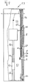
- the cabinet shown in FIGS. 1 to 3 consists of a body part with Side walls 1, 2, a rear wall 3 and bottom and top walls 4, 5.
- the Cabinet is provided with an upper partition 6, which this in an upper Compartment 7, which is open in the closed position of the rectangular locking elements 8, 9 and divides a lower compartment 10 which is open when the closure elements 8, 9 have been moved into their upper, overlapping position, in which they close compartment 3.
- an upper partition 6 which this in an upper Compartment 7, which is open in the closed position of the rectangular locking elements 8, 9 and divides a lower compartment 10 which is open when the closure elements 8, 9 have been moved into their upper, overlapping position, in which they close compartment 3.
- the upper closure element 8 in its lower central region with a knob or bow-shaped handle 11 provided.
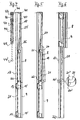
- the inner sides of the side walls 1, 2 are on the outer edge regions Provides guides 12 for guide rollers of the closure elements, which are based on the 4 to 6 are explained in more detail.
- the lower closure element 9 is on both sides in the area of the upper sides of the side Edge areas provided with angled support pieces 13, 14, the right angle angled mounting leg 13 ', 14' in particular from the 7 and 8, screwed with the lower closure element 9 are.
- On the inward ridges running at right angles to the closure element Legs of the support pieces are on axes perpendicular to these standing axes three rollers 15 freely rotatable, of which the outer two rollers 15 on the outer flank 16 of the guide groove 17 and the middle roller 15 run on the inner flank in the manner shown in FIG. 7.
- To the Carrier piece 13 is another roller 16 freely rotatable about an axis, the is perpendicular to the axes of the rollers 15.
- the roller 16 runs on the Web part of the guide groove 17, so that a straight and tilt-free run ensures the lower closure element 9 in the linear guides 17 is.
- the linear guides 17 extend essentially over the entire Height of the inside of the side walls of the cabinet.
- the guides screwed onto the inside of the side walls on both sides are made made of plastic molded parts 18, which on the inside with the straight lines Guide grooves 17 and on their outer sides with the guide grooves 19, 24 for the provided upper and lower guide rollers 21, 22 of the upper closure element 8 are.
- the guide grooves 19 for the lower guide rollers 22 consist of a Main section 20, which runs parallel to the guide groove 17, and a lower approximately right-angled guide portion 20 ', the end portion about stands at right angles on the guide groove 17.
- the upper flank of the guide groove 20 ' is provided with a rounded recess 20 'in which the guide rollers 22 rest in the closed position shown in FIG. 4.
- the upper guide grooves 24 also consist of an upper parallel to the Guide groove 17 extending portion 24 'and a lower inclined Section 25.
- the guide rollers 21, 22 can be seen in particular from FIGS. 7 and 8 Way mounted on support pieces 26 which are designed as elbows, whose one leg 27 is screwed to the closure element 8. To the other inwardly projecting legs 28, the rollers 21, 22 are mounted.
- Deflection rollers 30 are freely rotatably mounted on axes on the upper support pieces 26, over which a flexible rope 31, for example a rope made of steel wire, runs, one end of which at a fixed point 32 in the lower end region of the with the guide grooves provided fitting 18 is attached and the other end thereof is attached to the upper support pieces 13 of the lower closure elements.
- a flexible rope 31 for example a rope made of steel wire
- the holes cut at right angles from threaded holes are screwed into the retaining screws 36.
- the ends of the cables 31 inserted into the holes are held in a clamped manner.
- a flexible rope 40 In bores 37 of holding parts 38 arranged on the upper support pieces 26 are the ends of a flexible rope 40 through the holes 37 crossing clamping screws 39 held.
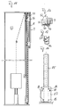
- the flexible ropes 40 run over deflection rollers 41 in the upper one Area of the shaped pieces 18 provided with the guide grooves, via deflection rollers 42, the bearing pieces screwed to the side walls of the cabinet 43 are mounted, and deflection rollers 44, which are on the outer ends of the piston rods are supported by gas springs 45 to their fixed points 46 on the bearing pieces 43.
- the positions of the deflection roller 44 are in the closed position displaced closure elements 8, 9 shown in full lines, while the position of the deflection rollers 44 'in the open position shown in FIG. 6 the closure elements are indicated with dashed lines.
- FIGS. 9 to 10 another embodiment of the management of the Closure elements 8, 9 described, which differ from that according to FIGS. 4 to 6 distinguishes that the lower closure element when moving the closure elements 8, 9 in the open position overlapping the upper closure element runs over and lies in the manner shown in FIGS. 10 and 11 outside.
- the upper closure element 8 is provided with upper and lower guide pieces 50, 60 provided on which the rollers 51, 61 are mounted, in the outer guide rail 52 are performed.
- the guide rail 52 extends essentially over the entire height of the side wall 53 of the cabinet 54.
- the lower end portions of the inner guide rails 55 are over an arc piece provided with a right-angled bend 57, in the closed position the rollers of the upper locking pieces 56 of the lower locking element 9 lie.
- the lower end portion of the guide 52 is slanted inward outgoing guide piece 58 provided with a straight end piece 59, in which the Rolling the lower guide pieces 62 of the lower closure piece 9 in the closed position lie.
- the two closure elements 8, 9 are pulley-like together by a rope 64 connected.
- the rope 64 runs from a lower fixed point 32 in the area of Bottom of the cabinet via a deflection roller 30, which is attached to the upper guide pieces 50 of the upper closure element 8 is mounted to a fixed point 35 the upper guide pieces 56 of the lower closure element 9.
- closure elements 8, 9 are in their position shown in FIG. 9 in their closed position, in which they are flush with one another.
- the lower closure element 9 is on its upper End area with a handle, not shown, through which the can pull out the upper end area in the direction of arrow A until the lower Closure element 9 is in a slightly tilted position in which the upper Edge of the lower closure element 9 the lower edge of the upper closure element 8 can run over smoothly.
- the extension route is through the Length of the angled branches 57 of the guide 55 is determined. Now becomes the lower one Closure element moved upwards, the guide rollers of the lower run Guide pieces 62 of the lower closure element 9 over the inclined branch 58 of the guides into the guides 52.
- the upper guide pieces 50 form, as it were, rope bottles for the rope reeving, the counterweight is dimensioned such that it is not only the upper closure element 8 automatically when lifting the lower closure element 9 moved above, but also a relieving force on the lower Closure element 9 exercises in such a way that both closure elements in their respective situation.
- the counterweight is 70 guided on a pull-out rail 72 of a pull-out guide for drawers.
- a additional counterweight 73 is with the middle rail 74 of the pull-out system Drawer guide connected.
- the body rail 75 of the pull-out rail system the drawer guide is screwed to the cabinet side wall 53.
- the the counterweight 73 carrying center rails 74 are connected to the Extension rails attached.
- the pull-out mechanism of drawer guides is known per se and therefore need not be described in more detail.
- the 14 is a guide rail to be attached to the side walls 53 of the cabinet 85 can be seen on which a carriage can be moved over the rollers 86 is guided, which carries a plate 87 as a counterweight.
- the plate 87 is keyhole-like Provide holes 88 in the additional weights for the purpose of balancing can be hung.
Landscapes
- Engineering & Computer Science (AREA)
- Civil Engineering (AREA)
- Structural Engineering (AREA)
- Mechanical Engineering (AREA)
- Table Devices Or Equipment (AREA)
- Acyclic And Carbocyclic Compounds In Medicinal Compositions (AREA)
- Support Devices For Sliding Doors (AREA)
- Extensible Doors And Revolving Doors (AREA)
- Drawers Of Furniture (AREA)
- Operating, Guiding And Securing Of Roll- Type Closing Members (AREA)
Applications Claiming Priority (2)
| Application Number | Priority Date | Filing Date | Title |
|---|---|---|---|
| DE29807679U DE29807679U1 (de) | 1998-04-28 | 1998-04-28 | Verschluß für Öffnungen aller Art, vorzugsweise für Möbel |
| DE29807679U | 1998-04-28 |
Publications (3)
| Publication Number | Publication Date |
|---|---|
| EP0953713A2 true EP0953713A2 (fr) | 1999-11-03 |
| EP0953713A3 EP0953713A3 (fr) | 2000-11-08 |
| EP0953713B1 EP0953713B1 (fr) | 2007-08-22 |
Family
ID=8056429
Family Applications (1)
| Application Number | Title | Priority Date | Filing Date |
|---|---|---|---|
| EP99108012A Expired - Lifetime EP0953713B1 (fr) | 1998-04-28 | 1999-04-22 | Fermetures pour ouvertures de toutes sortes, notamment pour meubles |
Country Status (4)
| Country | Link |
|---|---|
| EP (1) | EP0953713B1 (fr) |
| AT (1) | ATE371081T1 (fr) |
| DE (2) | DE29807679U1 (fr) |
| ES (1) | ES2291003T3 (fr) |
Cited By (5)
| Publication number | Priority date | Publication date | Assignee | Title |
|---|---|---|---|---|
| ITMI20082001A1 (it) * | 2008-11-11 | 2010-05-12 | Caimi Export Spa | Dispositivo per la movimentazione verticale di ante per mobili. |
| CN101105099B (zh) * | 2006-07-12 | 2012-01-11 | 德胜(苏州)洋楼有限公司 | 提拉窗平衡装置 |
| EP2821576A1 (fr) * | 2013-07-05 | 2015-01-07 | Verdonck Development & Systems | Armoire automatisée |
| EP3228800A1 (fr) | 2016-04-08 | 2017-10-11 | Dada S.p.a. | Ensemble pour ouvrir et élément de meubles, en particulier pour les cuisinières |
| CN113137159A (zh) * | 2021-03-30 | 2021-07-20 | 佛山市磁家有导科技有限公司 | 一种绳缆传动的飘移门/窗 |
Families Citing this family (4)
| Publication number | Priority date | Publication date | Assignee | Title |
|---|---|---|---|---|
| HU219724B (hu) | 1998-07-28 | 2001-07-30 | Arturo Salice S.P.A. | Működtető berendezés függőleges irányban eltolható záróelemmel |
| ITMI20080098A1 (it) * | 2008-01-23 | 2009-07-24 | Caimi Export Spa | Dispositivo per la movimentazione verticale di ante per mobili |
| ITMI20130534A1 (it) * | 2013-04-08 | 2014-10-09 | Dada S P A | Componente di arredo per mobile |
| DE102017107568A1 (de) * | 2017-04-07 | 2018-10-11 | Hettich-Heinze Gmbh & Co. Kg | Möbelbeschlag für eine Schiebebewegung einer mehrteiligen Tür und Möbel mit einem derartigen Möbelbeschlag |
Family Cites Families (8)
| Publication number | Priority date | Publication date | Assignee | Title |
|---|---|---|---|---|
| FR583020A (fr) * | 1924-06-21 | 1925-01-05 | Portes à coulisse pour armoires et châssis à guillotine | |
| US3000437A (en) * | 1956-01-16 | 1961-09-19 | Howard J Bennett | Sliding multiple door assembly and interior cabinet |
| FR87654E (fr) * | 1963-10-02 | 1966-09-23 | Porte relevable | |
| DE2601969C3 (de) * | 1976-01-20 | 1979-10-04 | Eltreva Ag, Aesch (Schweiz) | Vertikalschiebefenster |
| DE3343366A1 (de) * | 1983-11-30 | 1985-06-05 | Schaumburg-Lippische Baubeschlag-Fabrik W. Hautau GmbH, 3061 Helpsen | Beschlag fuer den schiebefluegel von fenstern oder tueren |
| DE3442107A1 (de) * | 1984-11-17 | 1986-05-22 | Glos, Georg, 8700 Würzburg | Vertikalschiebefenster |
| NL9402109A (nl) * | 1994-12-12 | 1996-07-01 | Polynorm Nv | Deur. |
| DE29714615U1 (de) * | 1997-08-14 | 1997-11-27 | Schieffer Tor- und Schutzsysteme GmbH, 59557 Lippstadt | Tür- oder Torverschluß |
-
1998
- 1998-04-28 DE DE29807679U patent/DE29807679U1/de not_active Expired - Lifetime
-
1999
- 1999-04-22 ES ES99108012T patent/ES2291003T3/es not_active Expired - Lifetime
- 1999-04-22 EP EP99108012A patent/EP0953713B1/fr not_active Expired - Lifetime
- 1999-04-22 AT AT99108012T patent/ATE371081T1/de active
- 1999-04-22 DE DE59914463T patent/DE59914463D1/de not_active Expired - Lifetime
Non-Patent Citations (1)
| Title |
|---|
| None |
Cited By (6)
| Publication number | Priority date | Publication date | Assignee | Title |
|---|---|---|---|---|
| CN101105099B (zh) * | 2006-07-12 | 2012-01-11 | 德胜(苏州)洋楼有限公司 | 提拉窗平衡装置 |
| ITMI20082001A1 (it) * | 2008-11-11 | 2010-05-12 | Caimi Export Spa | Dispositivo per la movimentazione verticale di ante per mobili. |
| EP2184430A1 (fr) | 2008-11-11 | 2010-05-12 | CAIMI EXPORT S.p.A. | Dispositif pour entraîner verticalement des ailes de meubles |
| EP2821576A1 (fr) * | 2013-07-05 | 2015-01-07 | Verdonck Development & Systems | Armoire automatisée |
| EP3228800A1 (fr) | 2016-04-08 | 2017-10-11 | Dada S.p.a. | Ensemble pour ouvrir et élément de meubles, en particulier pour les cuisinières |
| CN113137159A (zh) * | 2021-03-30 | 2021-07-20 | 佛山市磁家有导科技有限公司 | 一种绳缆传动的飘移门/窗 |
Also Published As
| Publication number | Publication date |
|---|---|
| EP0953713B1 (fr) | 2007-08-22 |
| EP0953713A3 (fr) | 2000-11-08 |
| DE59914463D1 (de) | 2007-10-04 |
| ES2291003T3 (es) | 2008-02-16 |
| DE29807679U1 (de) | 1998-08-06 |
| ATE371081T1 (de) | 2007-09-15 |
Similar Documents
| Publication | Publication Date | Title |
|---|---|---|
| EP0706012B1 (fr) | Four de cuisson | |
| EP3654803B2 (fr) | Meuble avec une machine à café ou un grille-pain et procédé d'ouverture d'une porte | |
| AT392321B (de) | Beschlag fuer mit schwenk-schiebetueren ausgestattete kastenmoebel u. dgl. | |
| EP1168945A1 (fr) | Tiroir d'armoire telescopique | |
| EP0441919B1 (fr) | Element de meuble pour la mise en place dans un coin rectangulaire d'une piece | |
| EP0953713B1 (fr) | Fermetures pour ouvertures de toutes sortes, notamment pour meubles | |
| DE69002837T2 (de) | Vorrichtung mit zwei sich auseinanderbewegenden Läden. | |
| DE2419546C3 (de) | Schrank mit herausziehbaren Schubladenelementen | |
| DE10329798A1 (de) | Sektionaltor | |
| DE4410051C2 (de) | Sektionaltor | |
| DE19514009A1 (de) | Eckschrank zum Aufstellen in einer Raumecke | |
| EP4186823B1 (fr) | Sas de transfert de marchandises | |
| EP2837763B1 (fr) | Butée de porte coulissante et mobilier | |
| EP1437469B1 (fr) | Fenêtre | |
| DE102010061137B4 (de) | Duschtrennwand oder -kabine | |
| EP1253274A2 (fr) | Rail de guidage pour éléments de portes coulissantes | |
| DE8802208U1 (de) | Dreh-Schiebetürbeschlag für ein Möbel | |
| EP4437906B1 (fr) | Tiroir pour une zone supérieure d'armoire - en forme d'un agencement de rails pour faciliter l'accessibilité du contenu | |
| DE4223608A1 (de) | Back- und Bratofen | |
| EP0523424B1 (fr) | Dispositif de guidage pour tiroir | |
| EP0728902B1 (fr) | Volet roulant pour meuble du type armoire | |
| DE2932730B1 (de) | Beschlag fuer eine haengende Schiebetuere eines Kofferaufbaus von Transportfahrzeugen | |
| EP0477578B1 (fr) | Cloison | |
| DE8231409U1 (de) | Fuehrungsvorrichtung fuer schubkaesten mit seitlich abstehenden schuerzen | |
| DE2237395A1 (de) | Glasschiebetuer, insbesondere fuer ganzglas-vitrinen |
Legal Events
| Date | Code | Title | Description |
|---|---|---|---|
| PUAI | Public reference made under article 153(3) epc to a published international application that has entered the european phase |
Free format text: ORIGINAL CODE: 0009012 |
|
| AK | Designated contracting states |
Kind code of ref document: A2 Designated state(s): AT DE ES IT |
|
| AX | Request for extension of the european patent |
Free format text: AL;LT;LV;MK;RO;SI PAYMENT 19990422 |
|
| PUAL | Search report despatched |
Free format text: ORIGINAL CODE: 0009013 |
|
| AK | Designated contracting states |
Kind code of ref document: A3 Designated state(s): AT BE CH CY DE DK ES FI FR GB GR IE IT LI LU MC NL PT SE |
|
| AX | Request for extension of the european patent |
Free format text: AL;LT;LV;MK;RO;SI PAYMENT 19990422 |
|
| 17P | Request for examination filed |
Effective date: 20010202 |
|
| AKX | Designation fees paid |
Free format text: AT DE ES IT |
|
| AXX | Extension fees paid |
Free format text: SI PAYMENT 19990422 |
|
| GRAP | Despatch of communication of intention to grant a patent |
Free format text: ORIGINAL CODE: EPIDOSNIGR1 |
|
| GRAS | Grant fee paid |
Free format text: ORIGINAL CODE: EPIDOSNIGR3 |
|
| GRAA | (expected) grant |
Free format text: ORIGINAL CODE: 0009210 |
|
| AK | Designated contracting states |
Kind code of ref document: B1 Designated state(s): AT DE ES IT |
|
| AX | Request for extension of the european patent |
Extension state: SI |
|
| REF | Corresponds to: |
Ref document number: 59914463 Country of ref document: DE Date of ref document: 20071004 Kind code of ref document: P |
|
| REG | Reference to a national code |
Ref country code: ES Ref legal event code: FG2A Ref document number: 2291003 Country of ref document: ES Kind code of ref document: T3 |
|
| PLBE | No opposition filed within time limit |
Free format text: ORIGINAL CODE: 0009261 |
|
| STAA | Information on the status of an ep patent application or granted ep patent |
Free format text: STATUS: NO OPPOSITION FILED WITHIN TIME LIMIT |
|
| 26N | No opposition filed |
Effective date: 20080526 |
|
| PGFP | Annual fee paid to national office [announced via postgrant information from national office to epo] |
Ref country code: AT Payment date: 20140402 Year of fee payment: 16 Ref country code: IT Payment date: 20140429 Year of fee payment: 16 Ref country code: ES Payment date: 20140428 Year of fee payment: 16 Ref country code: DE Payment date: 20140429 Year of fee payment: 16 |
|
| REG | Reference to a national code |
Ref country code: DE Ref legal event code: R119 Ref document number: 59914463 Country of ref document: DE |
|
| REG | Reference to a national code |
Ref country code: AT Ref legal event code: MM01 Ref document number: 371081 Country of ref document: AT Kind code of ref document: T Effective date: 20150422 |
|
| PG25 | Lapsed in a contracting state [announced via postgrant information from national office to epo] |
Ref country code: IT Free format text: LAPSE BECAUSE OF NON-PAYMENT OF DUE FEES Effective date: 20150422 Ref country code: DE Free format text: LAPSE BECAUSE OF NON-PAYMENT OF DUE FEES Effective date: 20151103 |
|
| PG25 | Lapsed in a contracting state [announced via postgrant information from national office to epo] |
Ref country code: AT Free format text: LAPSE BECAUSE OF NON-PAYMENT OF DUE FEES Effective date: 20150422 |
|
| PG25 | Lapsed in a contracting state [announced via postgrant information from national office to epo] |
Ref country code: ES Free format text: LAPSE BECAUSE OF NON-PAYMENT OF DUE FEES Effective date: 20150423 |
|
| REG | Reference to a national code |
Ref country code: ES Ref legal event code: FD2A Effective date: 20180704 |