EP0953815A2 - Anschlussvorrichtung für Wärmetauscher - Google Patents
Anschlussvorrichtung für Wärmetauscher Download PDFInfo
- Publication number
- EP0953815A2 EP0953815A2 EP99108281A EP99108281A EP0953815A2 EP 0953815 A2 EP0953815 A2 EP 0953815A2 EP 99108281 A EP99108281 A EP 99108281A EP 99108281 A EP99108281 A EP 99108281A EP 0953815 A2 EP0953815 A2 EP 0953815A2
- Authority
- EP
- European Patent Office
- Prior art keywords
- heat exchanger
- connecting device
- bores
- tubular member
- connector body
- Prior art date
- Legal status (The legal status is an assumption and is not a legal conclusion. Google has not performed a legal analysis and makes no representation as to the accuracy of the status listed.)
- Granted
Links
Images


Classifications
-
- F—MECHANICAL ENGINEERING; LIGHTING; HEATING; WEAPONS; BLASTING
- F28—HEAT EXCHANGE IN GENERAL
- F28D—HEAT-EXCHANGE APPARATUS, NOT PROVIDED FOR IN ANOTHER SUBCLASS, IN WHICH THE HEAT-EXCHANGE MEDIA DO NOT COME INTO DIRECT CONTACT
- F28D1/00—Heat-exchange apparatus having stationary conduit assemblies for one heat-exchange medium only, the media being in contact with different sides of the conduit wall, in which the other heat-exchange medium is a large body of fluid, e.g. domestic or motor car radiators
- F28D1/02—Heat-exchange apparatus having stationary conduit assemblies for one heat-exchange medium only, the media being in contact with different sides of the conduit wall, in which the other heat-exchange medium is a large body of fluid, e.g. domestic or motor car radiators with heat-exchange conduits immersed in the body of fluid
- F28D1/03—Heat-exchange apparatus having stationary conduit assemblies for one heat-exchange medium only, the media being in contact with different sides of the conduit wall, in which the other heat-exchange medium is a large body of fluid, e.g. domestic or motor car radiators with heat-exchange conduits immersed in the body of fluid with plate-like or laminated conduits
- F28D1/0308—Heat-exchange apparatus having stationary conduit assemblies for one heat-exchange medium only, the media being in contact with different sides of the conduit wall, in which the other heat-exchange medium is a large body of fluid, e.g. domestic or motor car radiators with heat-exchange conduits immersed in the body of fluid with plate-like or laminated conduits the conduits being formed by paired plates touching each other
- F28D1/0325—Heat-exchange apparatus having stationary conduit assemblies for one heat-exchange medium only, the media being in contact with different sides of the conduit wall, in which the other heat-exchange medium is a large body of fluid, e.g. domestic or motor car radiators with heat-exchange conduits immersed in the body of fluid with plate-like or laminated conduits the conduits being formed by paired plates touching each other the plates having lateral openings therein for circulation of the heat-exchange medium from one conduit to another
- F28D1/0333—Heat-exchange apparatus having stationary conduit assemblies for one heat-exchange medium only, the media being in contact with different sides of the conduit wall, in which the other heat-exchange medium is a large body of fluid, e.g. domestic or motor car radiators with heat-exchange conduits immersed in the body of fluid with plate-like or laminated conduits the conduits being formed by paired plates touching each other the plates having lateral openings therein for circulation of the heat-exchange medium from one conduit to another the plates having integrated connecting members
- F28D1/0341—Heat-exchange apparatus having stationary conduit assemblies for one heat-exchange medium only, the media being in contact with different sides of the conduit wall, in which the other heat-exchange medium is a large body of fluid, e.g. domestic or motor car radiators with heat-exchange conduits immersed in the body of fluid with plate-like or laminated conduits the conduits being formed by paired plates touching each other the plates having lateral openings therein for circulation of the heat-exchange medium from one conduit to another the plates having integrated connecting members with U-flow or serpentine-flow inside the conduits
-
- F—MECHANICAL ENGINEERING; LIGHTING; HEATING; WEAPONS; BLASTING
- F28—HEAT EXCHANGE IN GENERAL
- F28F—DETAILS OF HEAT-EXCHANGE AND HEAT-TRANSFER APPARATUS, OF GENERAL APPLICATION
- F28F9/00—Casings; Header boxes; Auxiliary supports for elements; Auxiliary members within casings
- F28F9/02—Header boxes; End plates
- F28F9/0246—Arrangements for connecting header boxes with flow lines
- F28F9/0251—Massive connectors, e.g. blocks; Plate-like connectors
- F28F9/0253—Massive connectors, e.g. blocks; Plate-like connectors with multiple channels, e.g. with combined inflow and outflow channels
-
- F—MECHANICAL ENGINEERING; LIGHTING; HEATING; WEAPONS; BLASTING
- F28—HEAT EXCHANGE IN GENERAL
- F28F—DETAILS OF HEAT-EXCHANGE AND HEAT-TRANSFER APPARATUS, OF GENERAL APPLICATION
- F28F9/00—Casings; Header boxes; Auxiliary supports for elements; Auxiliary members within casings
- F28F9/02—Header boxes; End plates
- F28F9/0246—Arrangements for connecting header boxes with flow lines
- F28F9/0256—Arrangements for coupling connectors with flow lines
Definitions
- the present invention relates to connecting devices for heat exchangers such as evaporators and condensers.
- aluminum as used herein and in the claims includes pure aluminum and aluminum alloys.
- a connecting device which comprises a connector having two horizontal through bores corresponding to the respective openings and fixed to the heat exchanger with the through bores in coincidence with the respective openings.
- the connector comprises a blocklike body adjacent to the heat exchanger, and two short tubular projections provided on the connector body around edges thereof defining the respective through bores and to be opposed to a connectable device, each of the tubular projections being in the form of a spigot fittable in a socket of the connectable device. Since the connector has the structure described above, the two spigot portions must be made from a large block of material by cutting. This not only causes waste of a large quantity of the material but also gives rise to the problem that after one of the spigot portions has been formed by cutting, this spigot portion interferes with the cutting operation for making the other spigot portion.
- An object of the present invention is to provide a connecting device for heat exchangers which is easy to make without involving waste of material.
- the present invention provides a connecting device for a heat exchanger having a fluid circulating channel formed with an opening at one end thereof and an opening at the other end thereof, the openings being formed as juxtaposed in one side of the heat exchanger, the connecting device comprising a blocklike connector body having two horizontal through bores corresponding to the respective openings and fixed to the heat exchanger with the through bores in coincidence with the respective openings, a tubular member being fluid-tightly fitted in each of the through bores and having a connecting end projecting toward a connectable device, the connecting end being in the form of a spigot fittable in a socket of the connectable device.
- the spigots thus provided need not be formed from a black of material by cutting.
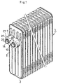
- the heat exchanger 1 has a fluid circulating channel formed with an opening 3 at one end thereof and an opening 4 at the other end thereof, the openings 3, 4 being formed as juxtaposed in one side of the heat exchanger 1.
- the illustrated connecting device C comprises a connector 72 having two horizontal through bores 70, 71 corresponding to the respective end openings 3, 4 and fixed to the heat exchanger 1 with the through bores 70, 71 in coincidence with the respective openings 3, 4.
- the connector 72 comprises a blocklike connector body 73 adjacent to the heat exchanger 1, and two short tubular projections provided on the connector body 73 around edges thereof defining the respective through bores 70, 71 and to be opposed to a connectable device, the tubular projections being in the form of spigots 74, 75 fittable in respective sockets of the connectable device. Since the two spigot portions 74, 75 must be formed by cutting a large block of material, the connector 72 has the foregoing problem.
- FIGS. 1 and 2 show this embodiment, i.e., a connecting device C1, for use with a heat exchanger 1 shown which has a fluid circulating channel 2 formed with an opening 3 at one end thereof and an opening 4 at the other end thereof, the openings 3, 4 being formed as juxtaposed in one side wall of the heat exchanger 1.
- the connecting device C1 comprises a blocklike connector body 7 having two horizontal through bores 5, 6 corresponding to the respective openings 3, 4 and fixed to the heat exchanger 1 with the through bores 5, 6 in coincidence with the respective openings 3, 4.
- Tubular members 8, 9 are fluid-tightly fitted in the respective through bores 5, 6, with connecting ends thereof projecting toward a connectable device 10 (i.e., device to be connected to the exchanger 1).
- the connecting ends of the tubular members 8, 9 are in the form of spigots 13, 14 fittable in respective sockets 11, 12 of the connectable device 10.
- the side wall of the heat exchanger 1 has an edge defining each of the openings 3, 4 and formed with an annular projection 15, and the connector body 7 has an edge defining each of the through bores 5, 6 and formed with an annular projection 16.
- the former annular projection 15 is fitted in and brazed to the latter annular projection 16 in lapping relation to thereby fix the connector body 7 to the heat exchanger 1.
- the connector body 7 is in the form of a horizontally elongated circle when seen from one side, and in the form of a horizontally elongated rectangle except the two annular projections 16 when seen from above.
- the connector body 7 is obtained by cutting an aluminum extrudate to a predetermined size and further cutting the resulting block as specified.
- each tubular member 8 (9) and the portion 17 (18) thereof fitted in the through bore 5 (6) are each formed with an annular groove 19, and an O-ring 20 is fitted in the annular groove 19.
- the fluid-tight fit of the tubular member 8 (9) in the through bore 5 (6) is realized by the O-ring 20.
- An annular positioning flange 21 is formed on the outer periphery of the tubular member 8 (9) approximately at the lengthwise midportion thereof, and the inner peripheral surface of the connector body 7 defining the through bore 5 (6) is formed with an annular stepped portion 22 for receiving the positioning flange 21.
- the through bore 5 (6) is tapered toward the bore end from the portion thereof where the extremity of the fitted portion 17 (18) of the tubular member 8 (9) therein is positioned, and the inner periphery of the connector body 7 defining the bore end is formed with an annular stepped portion for receiving the annular projection 15 around the opening 3 (4) of the fluid circulating channel 2.
- FIG. 3 shows this embodiment, i.e., a connecting device C2, for use with a heat exchanger 1.
- this embodiment has no annular positioning flange on the outer periphery of each of tubular portions 23, 24 approximately at the midportion thereof, and the inner periphery defining each of through bores 25, 26 correspondingly has no positioning flange bearing stepped portion.
- Embodiment 2 is substantially the same as Embodiment 1.
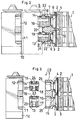
- FIGS. 4 and 5 show this embodiment, i.e., a connecting device C3, for use with a heat exchanger 1 shown which has a fluid circulating channel 2 formed with an opening 3 at one end thereof and an opening 4 at the other end thereof, the openings 3, 4 being formed as juxtaposed in one side wall of the heat exchanger 1.
- the connecting device C3 comprises a blocklike connector body 29 having two horizontal through bores 27, 28 corresponding to the respective openings 3, 4 and provided for the heat exchanger 1 with the through bores 27, 28 in coincidence with the respective openings 3, 4.
- Tubular members 30, 31 are fluid-tightly fitted in the respective through bores 27, 28, with connecting ends thereof projecting toward a connectable device 10 (i.e., device to be connected to the exchanger 1).
- the connecting ends of the tubular members 30, 31 are in the form of spigots 13, 14 fittable in respective sockets of the connectable device 10.
- the tubular members 30, 31 are fixed to the heat exchanger 1.
- the side wall of the heat exchanger 1 has an edge defining each of the openings 3, 4 and formed with an annular projection 15, and the connector body 29 has an edge defining each of the through bores 5, 6 and provided with an annular projection 32.
- the former annular projection 15 is fitted in and brazed to the latter annular projection 32 in lapping relation to thereby fix each tubular member 30 (31) to the heat exchanger 1.
- the annular projection 32 has a larger outer periphery than the tubular member 30 (31), whereby a connector body receiving stepped portion 32 is formed.
- the annular projection 32 has a larger inner periphery than the tubular member 30 (31), whereby an annular stepped portion is formed in the inner periphery of the edge of the bored portion for receiving the annular projection 15 around the opening 3 (4) of the channel 2.
- Each of the tubular members 30, 31 has an annular groove 19 formed in its spigot 13 (14) and an O-ring 20 fitted in the annular groove 19.
- the fluid-tight fit of the tubular member 30 (31) in the through bore 27 (28) is realized by enlarging the portion 34 (35) of the tubular member 30 (31) fitted in the through bore 27 (28).
- the portion 34 (35) is enlarged using a usual jig useful for enlarging pipes or tubes.
- the connecting device C3 is assembled in the order shown in FIG. 5 by inserting the tubular members 30, 31 through the respective bores 27, 28 of the blocklike connector body 29 as indicated by arrows in the drawing to engage the stepped portions 33 with the edges of the respective bored portions of the connector body 29.
- the tubular members 30, 31 are fixed to the heat exchanger 1 by brazing, the connector body 29 is consequently received by the stepped portions 33.
- the O-rings 20 are fitted into the respective annular grooves 19 after the tubular members 30, 31 have been fixed to the heat exchanger 1.
- the blocklike connector body 29 of the present embodiment is identical with the connector body 7 of Embodiment 1 in shape when seen from one side, and is perfectly in the form of a horizontally elongated rectangle when seen from above. Accordingly, the body 29 has no portion which needs to be made by cutting.
- the heat exchanger 1 is a multilayer evaporator, while the connectable device 10 is an expansion valve of the block type.
- the spigot 13 provides an inlet for a fluid, and the other spigot 14 provides an outlet for the fluid.
- like parts are designated by like reference numerals and are not described repeatedly.
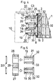
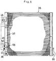
- FIGS. 6 and 7 show this embodiment, i.e., a connecting device C4, for use with a heat exchanger 36 shown which has as arranged at one side thereof a vertical upper header 37 and a vertical lower header 38 integral therewith.
- the upper header 37 and the lower header 38 have a lower-end opening 39 and an upper-end opening 40, respectively, as arranged in a vertical row.
- the connecting device C4 comprises a blocklike connector body 43 in the form of a vertically elongated rectangle in vertical section, having two through bores 41, 42 corresponding to the respective openings 39, 40 and fixed to the heat exchanger 36 with the through bores 41, 41 in coincidence with the respective openings 39, 40.
- Tubular members 44, 45 are fluid-tightly fitted in the respective through bores 41, 42 and each have a connecting end projecting toward a connectable device 46.
- the connecting ends are in the form of spigot 49, 50 fittable in respective sockets 47, 48 of the connectable device 46.
- a member 51 in the form of a short tube for positioning the connector body 43 is fixedly fitted in each of the openings 39, 40 so as to project into the header by a short length and into the connector body 43 by a long length.
- the connector body 43 has an inner peripheral surface defining each of the through bores 41, 42 and formed with an annular stepped portion 52 for receiving the positioning member 51, the bore-defining peripheral surface being formed, at one side thereof opposite to the positioning member 51, with an annular stepped portion 55 for receiving the portion 53 (54) of the tubular member 44 (45) fitted in.
- the spigot 49 (50) of the tubular member 44 (45) and the portion 53 (54) thereof fitted in the through bore 41 (42) are each formed with an annular groove 56, and an O-ring 57 is fitted in the annular groove 56.
- the fluid-tight fit of the tubular member 44 (45) in the through bore 41 (42) is realized by the O-ring 57.
- the upper header 37 is separated from the lower header 38 by a partition 58.
- FIG. 8 shows this embodiment, i.e., a connecting device C5.
- the connectable device 46 has the sockets 47, 48 in the outer periphery of its lower portion, whereas with this embodiment, sockets 60, 61 are formed in the bottom of a connectable device 59.
- the device C5 comprises a connector body 62 which is approximately square in vertical section and formed with L-shaped through bores 63, 64.
- the upper end of the connector body 62 has an inner peripheral surface defining each of each through bore 63 (64) and formed with an annular stepped portion 65, which faces upward for receiving the portion 53 (54) of each tubular member 44 (45) fitted in the connector body 62.
- Embodiment 5 is substantially the same as Embodiment 4.
- like parts are designated by like reference numerals and will not be described repeatedly.
- the heat exchanger 36 is a condenser having a supercooling unit which is provided by the portion of the heat exchanger below a horizontal plane through the boundary between the upper header 37 and the lower header 38, while each of the connectable devices 46, 59 is a liquid receiver.
- the spigot 49 provides an outlet for a fluid, i.e., the refrigerant subjected to condensation by the condenser, and the other spigot 50 provides an inlet of the supercooling unit 66 for the fluid, i.e., the refrigerant as passed through the receiver, that is, as purified.
- the tubular members 8, 9, 23, 24, 30, 31, 44, 45 of Embodiments 1 to 5 are each obtained by cutting a hollow aluminum extrudate to a predetermined size and further cutting the resulting piece as specified.
Landscapes
- Engineering & Computer Science (AREA)
- Physics & Mathematics (AREA)
- Thermal Sciences (AREA)
- Mechanical Engineering (AREA)
- General Engineering & Computer Science (AREA)
- Details Of Heat-Exchange And Heat-Transfer (AREA)
- Heat-Exchange Devices With Radiators And Conduit Assemblies (AREA)
- Steam Or Hot-Water Central Heating Systems (AREA)
- Compression-Type Refrigeration Machines With Reversible Cycles (AREA)
Applications Claiming Priority (2)
| Application Number | Priority Date | Filing Date | Title |
|---|---|---|---|
| JP12049698 | 1998-04-30 | ||
| JP12049698 | 1998-04-30 |
Publications (3)
| Publication Number | Publication Date |
|---|---|
| EP0953815A2 true EP0953815A2 (de) | 1999-11-03 |
| EP0953815A3 EP0953815A3 (de) | 2000-05-03 |
| EP0953815B1 EP0953815B1 (de) | 2003-08-06 |
Family
ID=14787648
Family Applications (1)
| Application Number | Title | Priority Date | Filing Date |
|---|---|---|---|
| EP99108281A Expired - Lifetime EP0953815B1 (de) | 1998-04-30 | 1999-04-27 | Anschlussvorrichtung für Wärmetauscher |
Country Status (4)
| Country | Link |
|---|---|
| US (2) | US6220343B1 (de) |
| EP (1) | EP0953815B1 (de) |
| AT (1) | ATE246792T1 (de) |
| DE (1) | DE69910108T2 (de) |
Cited By (6)
| Publication number | Priority date | Publication date | Assignee | Title |
|---|---|---|---|---|
| FR2826437A1 (fr) * | 2001-06-20 | 2002-12-27 | Valeo Climatisation | Dispositif de raccordement pour evaporateur de climatisation de vehicule |
| EP1314946A1 (de) | 2001-11-16 | 2003-05-28 | Behr GmbH & Co. | Wärmeübertrager, insbesondere Verdampfer |
| DE102006033771A1 (de) * | 2006-07-21 | 2008-01-24 | Modine Manufacturing Co., Racine | Wärmetauscher |
| NL2001263C2 (nl) * | 2008-02-07 | 2009-08-11 | Wth Vloerverwarming B V | Verdelersamenstel voor aansluiting van een veelheid leidingen voor vloeistof van een verwarmings- en/of koel-systeem. |
| CN104648174A (zh) * | 2013-11-22 | 2015-05-27 | 福特全球技术公司 | 用于电动车辆电池组的耦合器 |
| US9726382B2 (en) | 2010-07-30 | 2017-08-08 | Grundfos Management A/S | Heat exchanger unit having connectors with identical base elements |
Families Citing this family (30)
| Publication number | Priority date | Publication date | Assignee | Title |
|---|---|---|---|---|
| DE19957946B4 (de) * | 1999-12-02 | 2005-07-14 | Behr Gmbh & Co. Kg | Anschlußstutzen für einen Wärmeübertrager |
| JP2001289589A (ja) * | 2000-04-06 | 2001-10-19 | Sanden Corp | 熱交換器の配管接続構造 |
| JP3805628B2 (ja) * | 2001-01-29 | 2006-08-02 | 株式会社ヴァレオサーマルシステムズ | 熱交換器 |
| US6776225B2 (en) * | 2002-06-13 | 2004-08-17 | Delphi Technologies, Inc. | Heat exchanger assembly |
| JP4180359B2 (ja) * | 2002-11-29 | 2008-11-12 | カルソニックカンセイ株式会社 | 熱交換器 |
| JP4222137B2 (ja) * | 2003-07-22 | 2009-02-12 | 株式会社デンソー | 放熱器 |
| JP2005147427A (ja) * | 2003-11-11 | 2005-06-09 | Sanden Corp | 積層型熱交換器 |
| CA2454283A1 (en) * | 2003-12-29 | 2005-06-29 | Anis Muhammad | Insert molded structure and method for the manufacture thereof |
| US7077194B2 (en) * | 2004-02-26 | 2006-07-18 | Denso International America, Inc. | Brazed condenser jumper tube |
| DE102004028655A1 (de) * | 2004-06-15 | 2006-01-05 | Behr Gmbh & Co. Kg | Wärmeübertrager, insbesondere gelöteter Heizkörper |
| WO2006015037A2 (en) * | 2004-07-30 | 2006-02-09 | Ingersoll-Rand Company | Compressor air cooler with replaceable flange ring |
| US7540431B2 (en) * | 2004-11-24 | 2009-06-02 | Dana Canada Corporation | By-pass valve for heat exchanger |
| JP4797998B2 (ja) * | 2006-02-17 | 2011-10-19 | 株式会社デンソー | 熱交換器の配管継手構造及び熱交換器の配管組み付け方法 |
| JP4345843B2 (ja) * | 2007-04-27 | 2009-10-14 | 株式会社デンソー | 熱交換器 |
| US8430365B2 (en) * | 2008-04-03 | 2013-04-30 | Illinois Tool Works Inc. | Tube holding block assembly |
| JP4720855B2 (ja) * | 2008-06-02 | 2011-07-13 | 株式会社デンソー | 熱交換器 |
| US8052174B2 (en) * | 2008-09-15 | 2011-11-08 | Denso International America, Inc. | Pipe joint design |
| USD624166S1 (en) * | 2009-03-04 | 2010-09-21 | De'longhi Spa | Electric oil filled radiator |
| DE102010012869A1 (de) * | 2009-03-26 | 2010-09-30 | Modine Manufacturing Co., Racine | Wärmetauschermodul |
| US20120261097A1 (en) * | 2010-03-29 | 2012-10-18 | Zaffetti Mark A | Compact two sided cold plate with floating transfer tubes |
| US9644897B2 (en) * | 2010-06-15 | 2017-05-09 | Hanon Systems | Heater core with dual plate pipe connector |
| US10066878B2 (en) * | 2012-09-29 | 2018-09-04 | Zhejiang Sanhua Automotive Components Co., Ltd. | Heat exchanger integrated assembly and manufacturing method thereof |
| FR3006754B1 (fr) * | 2013-06-07 | 2015-06-26 | Valeo Systemes Thermiques | Module de connexion, echangeur thermique, et ensemble d'echange thermique correspondant |
| CN105518855B (zh) * | 2013-08-30 | 2018-07-06 | 株式会社电装 | 层叠型冷却器 |
| US9444124B2 (en) * | 2014-01-23 | 2016-09-13 | Lg Chem, Ltd. | Battery cell assembly and method for coupling a cooling fin to first and second cooling manifolds |
| USD834161S1 (en) * | 2016-02-08 | 2018-11-20 | Tomton S.R.O. | Heat exchanger |
| CN108895729B (zh) * | 2018-08-13 | 2024-08-02 | 浙江新昌同一汽车部件有限公司 | 一种汽车冷凝器与储液罐的连接结构 |
| JP7182070B2 (ja) * | 2018-09-27 | 2022-12-02 | 株式会社ノーリツ | 熱交換器およびその製造方法 |
| FR3093357B1 (fr) * | 2019-03-01 | 2021-05-14 | Valeo Systemes Thermiques | Dispositif de régulation thermique, notamment de refroidissement pour véhicule automobile |
| US12117251B2 (en) | 2020-02-19 | 2024-10-15 | Hanon Systems | Heat exchanger |
Family Cites Families (9)
| Publication number | Priority date | Publication date | Assignee | Title |
|---|---|---|---|---|
| US5163716A (en) * | 1991-10-25 | 1992-11-17 | General Motors Corporation | Condenser connector assembly for connecting refrigerant line |
| JP3159805B2 (ja) * | 1992-10-12 | 2001-04-23 | 昭和アルミニウム株式会社 | 熱交換器 |
| GB2290862A (en) * | 1994-06-24 | 1996-01-10 | Ford Motor Co | Heat exchanger hose connection |
| FR2722870B1 (fr) * | 1994-07-19 | 1996-09-06 | Valeo Thermique Moteur Sa | Dispositif de raccordement des tubulures d'entree et de sortie d'un echangeur de chaleur |
| GB9418526D0 (en) | 1994-09-14 | 1994-11-02 | Plessey Semiconductors Ltd | Semiconductor circuit arrangements |
| JPH0886536A (ja) * | 1994-09-14 | 1996-04-02 | Zexel Corp | 膨張弁取付部材 |
| JP3406424B2 (ja) * | 1995-06-09 | 2003-05-12 | サンデン株式会社 | 熱交換器の配管接続部構造 |
| US5911274A (en) * | 1995-12-06 | 1999-06-15 | Calsonic Corporation | Joint portion of heat exchanger |
| US5911127A (en) | 1997-06-05 | 1999-06-08 | Carrier Corporation | Prediction of chiller compressor motor overheating |
-
1999
- 1999-04-27 EP EP99108281A patent/EP0953815B1/de not_active Expired - Lifetime
- 1999-04-27 DE DE69910108T patent/DE69910108T2/de not_active Expired - Fee Related
- 1999-04-27 AT AT99108281T patent/ATE246792T1/de not_active IP Right Cessation
- 1999-04-29 US US09/301,329 patent/US6220343B1/en not_active Expired - Lifetime
-
2001
- 2001-03-14 US US09/805,557 patent/US6443223B2/en not_active Expired - Fee Related
Cited By (7)
| Publication number | Priority date | Publication date | Assignee | Title |
|---|---|---|---|---|
| FR2826437A1 (fr) * | 2001-06-20 | 2002-12-27 | Valeo Climatisation | Dispositif de raccordement pour evaporateur de climatisation de vehicule |
| EP1314946A1 (de) | 2001-11-16 | 2003-05-28 | Behr GmbH & Co. | Wärmeübertrager, insbesondere Verdampfer |
| DE102006033771A1 (de) * | 2006-07-21 | 2008-01-24 | Modine Manufacturing Co., Racine | Wärmetauscher |
| US8091617B2 (en) | 2006-07-21 | 2012-01-10 | Modine Manufacturing Company | Heat exchanger |
| NL2001263C2 (nl) * | 2008-02-07 | 2009-08-11 | Wth Vloerverwarming B V | Verdelersamenstel voor aansluiting van een veelheid leidingen voor vloeistof van een verwarmings- en/of koel-systeem. |
| US9726382B2 (en) | 2010-07-30 | 2017-08-08 | Grundfos Management A/S | Heat exchanger unit having connectors with identical base elements |
| CN104648174A (zh) * | 2013-11-22 | 2015-05-27 | 福特全球技术公司 | 用于电动车辆电池组的耦合器 |
Also Published As
| Publication number | Publication date |
|---|---|
| EP0953815A3 (de) | 2000-05-03 |
| DE69910108T2 (de) | 2004-05-27 |
| DE69910108D1 (de) | 2003-09-11 |
| US6443223B2 (en) | 2002-09-03 |
| ATE246792T1 (de) | 2003-08-15 |
| US20010010263A1 (en) | 2001-08-02 |
| EP0953815B1 (de) | 2003-08-06 |
| US6220343B1 (en) | 2001-04-24 |
Similar Documents
| Publication | Publication Date | Title |
|---|---|---|
| US6220343B1 (en) | Connecting device for heat exchanger | |
| AU648963B2 (en) | Heat exchanger | |
| EP0532794B1 (de) | Verteiler- und Wärmetauscheranordnung Verteiler- und Wärmetauscheranordnung | |
| US5183103A (en) | Heat exchanger | |
| US5918667A (en) | Heat exchanger | |
| EP0703425B1 (de) | Plattenwärmeaustauscher | |
| US7121329B2 (en) | Plastic tanked heat exchanger-side, header tank assembly | |
| US5911274A (en) | Joint portion of heat exchanger | |
| US5042578A (en) | Heat exchanger | |
| US5467818A (en) | Heat exchanger | |
| US5092398A (en) | Automotive parallel flow type heat exchanger | |
| JPH05272889A (ja) | 熱交換器 | |
| US4957158A (en) | Heat exchanger | |
| JPH05264126A (ja) | 冷媒分流器 | |
| JPH07301472A (ja) | ヘッダー | |
| JP2005351611A (ja) | 熱交換器および冷凍サイクルの冷媒流通部接続構造 | |
| EP0167978A2 (de) | Saugrohrwärmetauscher und Verfahren zur Herstellung | |
| US20060070724A1 (en) | Integrated receiver dryer sleeve | |
| US5346003A (en) | Face plumbed condenser for automotive air conditioner | |
| JP2000028231A (ja) | 熱交換器における接続装置 | |
| KR100538746B1 (ko) | 수액기 | |
| JPH0720524Y2 (ja) | 冷媒凝縮器用パイプ | |
| JPH10267464A (ja) | 膨張弁一体型蒸発器 | |
| JP3317672B2 (ja) | 熱交換器 | |
| KR20220030832A (ko) | 열교환기용 입출구 파이프의 플랜지고정구조 |
Legal Events
| Date | Code | Title | Description |
|---|---|---|---|
| PUAI | Public reference made under article 153(3) epc to a published international application that has entered the european phase |
Free format text: ORIGINAL CODE: 0009012 |
|
| AK | Designated contracting states |
Kind code of ref document: A2 Designated state(s): AT BE DE ES FR GB IT NL SE |
|
| AX | Request for extension of the european patent |
Free format text: AL;LT;LV;MK;RO;SI |
|
| PUAL | Search report despatched |
Free format text: ORIGINAL CODE: 0009013 |
|
| AK | Designated contracting states |
Kind code of ref document: A3 Designated state(s): AT BE CH CY DE DK ES FI FR GB GR IE IT LI LU MC NL PT SE |
|
| AX | Request for extension of the european patent |
Free format text: AL;LT;LV;MK;RO;SI |
|
| 17P | Request for examination filed |
Effective date: 20000926 |
|
| AKX | Designation fees paid |
Free format text: AT BE DE ES FR GB IT NL SE |
|
| RAP1 | Party data changed (applicant data changed or rights of an application transferred) |
Owner name: SHOWA DENKO K K |
|
| 17Q | First examination report despatched |
Effective date: 20010814 |
|
| RAP1 | Party data changed (applicant data changed or rights of an application transferred) |
Owner name: SHOWA DENKO K.K. |
|
| GRAH | Despatch of communication of intention to grant a patent |
Free format text: ORIGINAL CODE: EPIDOS IGRA |
|
| GRAH | Despatch of communication of intention to grant a patent |
Free format text: ORIGINAL CODE: EPIDOS IGRA |
|
| GRAA | (expected) grant |
Free format text: ORIGINAL CODE: 0009210 |
|
| AK | Designated contracting states |
Designated state(s): AT BE DE ES FR GB IT NL SE |
|
| PG25 | Lapsed in a contracting state [announced via postgrant information from national office to epo] |
Ref country code: NL Free format text: LAPSE BECAUSE OF FAILURE TO SUBMIT A TRANSLATION OF THE DESCRIPTION OR TO PAY THE FEE WITHIN THE PRESCRIBED TIME-LIMIT Effective date: 20030806 Ref country code: BE Free format text: LAPSE BECAUSE OF FAILURE TO SUBMIT A TRANSLATION OF THE DESCRIPTION OR TO PAY THE FEE WITHIN THE PRESCRIBED TIME-LIMIT Effective date: 20030806 Ref country code: AT Free format text: LAPSE BECAUSE OF FAILURE TO SUBMIT A TRANSLATION OF THE DESCRIPTION OR TO PAY THE FEE WITHIN THE PRESCRIBED TIME-LIMIT Effective date: 20030806 |
|
| REG | Reference to a national code |
Ref country code: GB Ref legal event code: FG4D |
|
| REF | Corresponds to: |
Ref document number: 69910108 Country of ref document: DE Date of ref document: 20030911 Kind code of ref document: P |
|
| PG25 | Lapsed in a contracting state [announced via postgrant information from national office to epo] |
Ref country code: SE Free format text: LAPSE BECAUSE OF FAILURE TO SUBMIT A TRANSLATION OF THE DESCRIPTION OR TO PAY THE FEE WITHIN THE PRESCRIBED TIME-LIMIT Effective date: 20031106 |
|
| PG25 | Lapsed in a contracting state [announced via postgrant information from national office to epo] |
Ref country code: ES Free format text: LAPSE BECAUSE OF FAILURE TO SUBMIT A TRANSLATION OF THE DESCRIPTION OR TO PAY THE FEE WITHIN THE PRESCRIBED TIME-LIMIT Effective date: 20031117 |
|
| NLV1 | Nl: lapsed or annulled due to failure to fulfill the requirements of art. 29p and 29m of the patents act | ||
| ET | Fr: translation filed | ||
| PLBE | No opposition filed within time limit |
Free format text: ORIGINAL CODE: 0009261 |
|
| STAA | Information on the status of an ep patent application or granted ep patent |
Free format text: STATUS: NO OPPOSITION FILED WITHIN TIME LIMIT |
|
| 26N | No opposition filed |
Effective date: 20040507 |
|
| PGFP | Annual fee paid to national office [announced via postgrant information from national office to epo] |
Ref country code: GB Payment date: 20070425 Year of fee payment: 9 |
|
| PGFP | Annual fee paid to national office [announced via postgrant information from national office to epo] |
Ref country code: IT Payment date: 20070528 Year of fee payment: 9 |
|
| PGFP | Annual fee paid to national office [announced via postgrant information from national office to epo] |
Ref country code: FR Payment date: 20070411 Year of fee payment: 9 |
|
| PGFP | Annual fee paid to national office [announced via postgrant information from national office to epo] |
Ref country code: DE Payment date: 20080502 Year of fee payment: 10 |
|
| GBPC | Gb: european patent ceased through non-payment of renewal fee |
Effective date: 20080427 |
|
| REG | Reference to a national code |
Ref country code: FR Ref legal event code: ST Effective date: 20081231 |
|
| PG25 | Lapsed in a contracting state [announced via postgrant information from national office to epo] |
Ref country code: FR Free format text: LAPSE BECAUSE OF NON-PAYMENT OF DUE FEES Effective date: 20080430 |
|
| PG25 | Lapsed in a contracting state [announced via postgrant information from national office to epo] |
Ref country code: GB Free format text: LAPSE BECAUSE OF NON-PAYMENT OF DUE FEES Effective date: 20080427 |
|
| PG25 | Lapsed in a contracting state [announced via postgrant information from national office to epo] |
Ref country code: IT Free format text: LAPSE BECAUSE OF NON-PAYMENT OF DUE FEES Effective date: 20080427 |
|
| PG25 | Lapsed in a contracting state [announced via postgrant information from national office to epo] |
Ref country code: DE Free format text: LAPSE BECAUSE OF NON-PAYMENT OF DUE FEES Effective date: 20091103 |