EP0954161A2 - Tambour à vide avec bords de conduits formés - Google Patents
Tambour à vide avec bords de conduits formés Download PDFInfo
- Publication number
- EP0954161A2 EP0954161A2 EP99201200A EP99201200A EP0954161A2 EP 0954161 A2 EP0954161 A2 EP 0954161A2 EP 99201200 A EP99201200 A EP 99201200A EP 99201200 A EP99201200 A EP 99201200A EP 0954161 A2 EP0954161 A2 EP 0954161A2
- Authority
- EP
- European Patent Office
- Prior art keywords
- drum
- vacuum
- edge
- holes
- stationary inner
- Prior art date
- Legal status (The legal status is an assumption and is not a legal conclusion. Google has not performed a legal analysis and makes no representation as to the accuracy of the status listed.)
- Withdrawn
Links
- 238000000034 method Methods 0.000 description 3
- 230000003287 optical effect Effects 0.000 description 2
- 238000012545 processing Methods 0.000 description 2
- 238000012993 chemical processing Methods 0.000 description 1
- 238000003384 imaging method Methods 0.000 description 1
- 238000007648 laser printing Methods 0.000 description 1
- 238000012986 modification Methods 0.000 description 1
- 230000004048 modification Effects 0.000 description 1
- 238000007639 printing Methods 0.000 description 1
- 230000001360 synchronised effect Effects 0.000 description 1
Images




Classifications
-
- H—ELECTRICITY
- H04—ELECTRIC COMMUNICATION TECHNIQUE
- H04N—PICTORIAL COMMUNICATION, e.g. TELEVISION
- H04N1/00—Scanning, transmission or reproduction of documents or the like, e.g. facsimile transmission; Details thereof
- H04N1/04—Scanning arrangements, i.e. arrangements for the displacement of active reading or reproducing elements relative to the original or reproducing medium, or vice versa
- H04N1/06—Scanning arrangements, i.e. arrangements for the displacement of active reading or reproducing elements relative to the original or reproducing medium, or vice versa using cylindrical picture-bearing surfaces, i.e. scanning a main-scanning line substantially perpendicular to the axis and lying in a curved cylindrical surface
- H04N1/08—Mechanisms for mounting or holding the sheet around the drum
- H04N1/083—Holding means
- H04N1/0856—Suction or vacuum means
-
- H—ELECTRICITY
- H04—ELECTRIC COMMUNICATION TECHNIQUE
- H04N—PICTORIAL COMMUNICATION, e.g. TELEVISION
- H04N1/00—Scanning, transmission or reproduction of documents or the like, e.g. facsimile transmission; Details thereof
- H04N1/04—Scanning arrangements, i.e. arrangements for the displacement of active reading or reproducing elements relative to the original or reproducing medium, or vice versa
- H04N1/06—Scanning arrangements, i.e. arrangements for the displacement of active reading or reproducing elements relative to the original or reproducing medium, or vice versa using cylindrical picture-bearing surfaces, i.e. scanning a main-scanning line substantially perpendicular to the axis and lying in a curved cylindrical surface
- H04N1/08—Mechanisms for mounting or holding the sheet around the drum
Definitions
- This invention relates generally to the field of photography, and in particular to a vacuum drum for scanning images on photographic paper.
- a customer delivers one or more rolls of film to a processing laboratory to have them chemically developed, and have hard copies of the images printed.
- Individual rolls of film are spliced together end to end to form a larger roll, or filmstrip, which is easily handled by automated equipment.
- each image is pre-scanned at high speed to obtain image characteristics, such as color and density. These characteristics are passed to an optical printer which uses the data to adjust exposure conditions such as duration and color filters of an image frame on the developed filmstrip.
- This image is optically projected onto a photosensitive paper. The exposed photosensitive paper is then chemically developed to yield the final hardcopy prints.
- images may be scanned to provide digital image files corresponding to each image on the film.
- These digital image files are usually stored on a recording medium such as a magnetic or optical disk and provided to the customer or made available to the customer over the Internet.
- the digital image files may be used to provide a hardcopy output using a digital printer which prints the images directly from the scanned data.
- a vacuum drum is comprised of a stationary inner drum with a vacuum port recessed in a surface of the stationary drum.
- the vacuum port connects a vacuum contained in an interior of the stationary inner drum with a surface of the inner drum.
- a rotating outer drum which has a common axis with the stationary inner drum, has vacuum holes connecting an inner and an outer surface of the rotating outer drum.
- the vacuum port has at least one edge which is not collinear with the axis of the rotating outer drum. The non-collinear edge exposes the vacuum holes in the outer drum in a sequential fashion so that all vacuum holes are not exposed simultaneously.
- Slow scan module 10 is comprised in general of a drum 12 housed in a drum frame 14.
- Motor 16 turns the drum 12 and a shaft encoder 18 provides velocity feedback information to servo control electronics 22, which controls the speed of the motor 16.
- Vacuum source 24 provides vacuum from an external source, not shown, to drum 12.
- Vacuum drum 12 is comprised of a rotating outer drum 30 and a stationary inner drum 40. Outer drum 30 and inner drum 40 are on a common axis 31. Rotating outer drum 30 has holes 32 and grooves 34. Exit guide grooves 35 in conjunction with exit guide fingers 15, shown in Fig. 7, are used to remove photographic paper and are deeper than vacuum grooves 34.
- a stationary inner drum 40 fitted within the rotating outer drum 30 is a stationary inner drum 40.
- the surface of stationary inner drum 40 has a helical edge vacuum port 50 which is recessed into the surface of the stationary inner drum 40.
- the vacuum port 50 exposes the outer drum 30 to a vacuum maintained in the interior 42 of stationary inner drum 40.
- a small gap 44 shown in Fig. 4, approximately 0.25 mm, is located between the stationary inner drum 40 and the outer drum 30. Gap 44 permits free motion of the outer drum yet provides sufficient resistance to air flow such that vacuum is ported through the holes 32 in the outer drum only when those holes are positioned above vacuum port 50.
- Port supply hole 46 connects the interior of stationary inner drum 40 with vacuum port 50.
- the axial row of holes 32 connected by radial grooves 34, near the lead edge 21 and trail edge 23 of the sheet of photographic paper 20.
- the force required to conform a flat sheet of the photographic paper to the drum is highest at these edges.
- the axial holes are approximately 6 mm apart. This small spacing ensures that maximum vacuum force is applied near the lead and trail edge of a randomly placed sheet of photographic paper. With this configuration, no synchronization of the drum and the paper feed are required to line up a lead edge of the photographic paper with a set of holes.
- the sheet photographic paper is wrapped 30° on the drum.
- There is no synchronization required between the drum and the input feed mechanism because an axial row of holes is provided every 6 mm around the entire perimeter of the drum.
- Narrow axial grooves approximately 0.6 mm wide, may be added to improve the hold down forces at the sheet's edges but are not shown in the figures. These axial grooves, if used, must be narrow so that lead and trail edges of a sheet does not deflect below the drum surface if the sheet edge is over the groove.
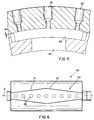
- Fig. 6 shows a plan view of stationary inner drum 40.
- Vacuum port 50 has edges 51 and 53 which are at an angle to the axis of rotation 31 of the outer drum 30. Since the vacuum holes 32 and rotating outer drum 30 are arranged approximately parallel to the axis 31 of the rotating drum and edges 51 and 53 are aligned at an angle to axis 31, vacuum holes 32 are exposed sequentially. This minimizes torque disturbances which would occur in the rotation of the drum if all the vacuum holes in a row where exposed simultaneously.
- Fig. 7 is a cross-sectional view which shows exit guide fingers 15 which cooperates with exit guide grooves 35 to lift a leading edge 21 of photographic sheet 20 from the surface of rotating outer drum 30.
- the vacuum port 50 is formed with a narrow portion 54 at the entrance and exit of the drum.
- the narrow portions are used to move the sheet photographic paper to and away from the wider portion where the sheets entire width will be held down for laser printing.
- the total number of holes open at one time is reduced, thus increasing the vacuum the photographic paper is exposed to by this method.
- the hole and groove pattern provides for a 120° wrap on the drum.
- the input sheet feed is synchronized with a specific axial lead edge vacuum groove 33 on the drum such that the lead edge of the photographic paper is placed just passed the axial lead edge vacuum groove of the drum.
- a second axial groove and holes is placed just inside of the lead and trail edge grooves providing additional holding force at the lead and trail edges of the sheet photographic paper.
- Radial vacuum grooves 34 are provided at the edges of the various sheet widths. Additional radial and axial grooves are provided between the perimeter grooves to evacuate any air under the center of the sheet.
- the drum circumference is sized such that the lead edge grooves become the trial edge grooves for the longest sheet, approximately 457 mm.
- the large wrap angle of the second embodiment leads to a large vacuum area.
- a specific hole and groove pattern was developed to minimize the number of open holes and maximize the vacuum pressure.
- the smaller wrap angle of the first embodiment permits a continuous and denser pattern of holes and grooves.
- the total number of open holes in each case is approximately equal and the resulting vacuum pressure applied is also equal.
- the radial grooves are replaced with a narrow, approximately 1.25 mm wide, helical groove with a close pitch 2.5 mm. This increases the groove area under the lead and trail edges.
- the 0.6 mm wide axial groove mentioned above is required to feed the helical grooves not directly connected to holes.
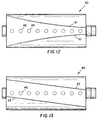
- Figs. 9-13 show variations in the edge configuration for vacuum port 50.
- edge 55 is a curved shape.
- the overall appearance presented by edge 55 is concave.
- Fig. 10 is similar to Fig. 9, except the curving edges 57 present a generally convex appearance.
- straight edges 59 converge toward one end of drum 40
- curved edges 61 converge toward one end of drum 40.
- Fig. 13 shows an alternate embodiment wherein curved edges 63 are parallel and non-collinear with the axis of rotating outer drum 30. In all these vacuum port embodiments, the edges are configured so that vacuum holes in the rotating outer drum 30 will not be exposed simultaneously, but rather, sequentially.
Landscapes
- Engineering & Computer Science (AREA)
- Multimedia (AREA)
- Signal Processing (AREA)
- Projection-Type Copiers In General (AREA)
- Rolls And Other Rotary Bodies (AREA)
- Feeding Of Articles By Means Other Than Belts Or Rollers (AREA)
- Magnetic Bearings And Hydrostatic Bearings (AREA)
Applications Claiming Priority (2)
| Application Number | Priority Date | Filing Date | Title |
|---|---|---|---|
| US6967298A | 1998-04-29 | 1998-04-29 | |
| US69672 | 1998-04-29 |
Publications (2)
| Publication Number | Publication Date |
|---|---|
| EP0954161A2 true EP0954161A2 (fr) | 1999-11-03 |
| EP0954161A3 EP0954161A3 (fr) | 2001-02-07 |
Family
ID=22090495
Family Applications (1)
| Application Number | Title | Priority Date | Filing Date |
|---|---|---|---|
| EP99201200A Withdrawn EP0954161A3 (fr) | 1998-04-29 | 1999-04-19 | Tambour à vide avec bords de conduits formés |
Country Status (2)
| Country | Link |
|---|---|
| EP (1) | EP0954161A3 (fr) |
| JP (1) | JP2000029145A (fr) |
Families Citing this family (1)
| Publication number | Priority date | Publication date | Assignee | Title |
|---|---|---|---|---|
| KR100815990B1 (ko) | 2006-12-18 | 2008-03-24 | 이규환 | 섬유원단가공용 회전식 진공흡입롤러 |
Citations (1)
| Publication number | Priority date | Publication date | Assignee | Title |
|---|---|---|---|---|
| JPH07127631A (ja) * | 1993-11-05 | 1995-05-16 | Berumateitsuku:Kk | 吸気幅可変型サクションローラ |
Family Cites Families (2)
| Publication number | Priority date | Publication date | Assignee | Title |
|---|---|---|---|---|
| US4705199A (en) * | 1985-06-28 | 1987-11-10 | Harris Graphics Corporation | Vacuum drum for securing a film thereto |
| JP2630870B2 (ja) * | 1991-07-17 | 1997-07-16 | 株式会社ベルマティック | サクションロール |
-
1999
- 1999-04-19 EP EP99201200A patent/EP0954161A3/fr not_active Withdrawn
- 1999-04-28 JP JP11121675A patent/JP2000029145A/ja active Pending
Patent Citations (1)
| Publication number | Priority date | Publication date | Assignee | Title |
|---|---|---|---|---|
| JPH07127631A (ja) * | 1993-11-05 | 1995-05-16 | Berumateitsuku:Kk | 吸気幅可変型サクションローラ |
Also Published As
| Publication number | Publication date |
|---|---|
| EP0954161A3 (fr) | 2001-02-07 |
| JP2000029145A (ja) | 2000-01-28 |
Similar Documents
| Publication | Publication Date | Title |
|---|---|---|
| US6343787B1 (en) | Sheeting transport apparatus having anti-positional offset mechanism | |
| JP2012128439A (ja) | 焼付け装置、焼付け方法及びコンピュータプログラム | |
| US5801852A (en) | Positive sleeving system for photographic negatives | |
| US20020140802A1 (en) | Image recording apparatus and method | |
| EP0954161A2 (fr) | Tambour à vide avec bords de conduits formés | |
| EP0867758B1 (fr) | Appareil d'enregistrement d'images et dispositif de distribution du matériau sensible à la lumière, pour l'usage dans l'appareil | |
| US7262878B2 (en) | System and method for calibrating an imaging system during imaging | |
| US6108070A (en) | Image recording apparatus | |
| JP3529211B2 (ja) | 画像位置情報の形成方法 | |
| US6935794B2 (en) | Image recording apparatus | |
| US6160608A (en) | Image recording apparatus | |
| JP4126631B2 (ja) | 写真焼付装置 | |
| JP2003043591A (ja) | 画像処理装置 | |
| JP3726218B2 (ja) | 副走査搬送機構 | |
| JP2002287266A (ja) | 誘いガイド | |
| JPH07319143A (ja) | 写真現像方法及び写真現像装置 | |
| JP3753519B2 (ja) | 画像記録装置 | |
| US6115102A (en) | Light-sensitive material transporting device | |
| JP2000010206A (ja) | 感光材料搬送装置 | |
| JPH11167170A (ja) | 走査搬送装置 | |
| JPH11194433A (ja) | 画像記録装置 | |
| JPH10333313A (ja) | 画像記録装置 | |
| JPH10301210A (ja) | 画像記録装置 | |
| JP2003221154A (ja) | 記録媒体の振分装置およびこれを用いた記録装置 | |
| JP2003156802A (ja) | 画像読取装置 |
Legal Events
| Date | Code | Title | Description |
|---|---|---|---|
| PUAI | Public reference made under article 153(3) epc to a published international application that has entered the european phase |
Free format text: ORIGINAL CODE: 0009012 |
|
| AK | Designated contracting states |
Kind code of ref document: A2 Designated state(s): DE FR GB |
|
| AX | Request for extension of the european patent |
Free format text: AL;LT;LV;MK;RO;SI |
|
| PUAL | Search report despatched |
Free format text: ORIGINAL CODE: 0009013 |
|
| AK | Designated contracting states |
Kind code of ref document: A3 Designated state(s): AT BE CH CY DE DK ES FI FR GB GR IE IT LI LU MC NL PT SE |
|
| AX | Request for extension of the european patent |
Free format text: AL;LT;LV;MK;RO;SI |
|
| 17P | Request for examination filed |
Effective date: 20010714 |
|
| AKX | Designation fees paid |
Free format text: DE FR GB |
|
| 17Q | First examination report despatched |
Effective date: 20020507 |
|
| STAA | Information on the status of an ep patent application or granted ep patent |
Free format text: STATUS: THE APPLICATION IS DEEMED TO BE WITHDRAWN |
|
| 18D | Application deemed to be withdrawn |
Effective date: 20020918 |