EP0955104A1 - Vorrichtung und verfahren zum wechseln von metallpressformen für plattendickereduzierende pressen und pressmetallform - Google Patents
Vorrichtung und verfahren zum wechseln von metallpressformen für plattendickereduzierende pressen und pressmetallform Download PDFInfo
- Publication number
- EP0955104A1 EP0955104A1 EP98951769A EP98951769A EP0955104A1 EP 0955104 A1 EP0955104 A1 EP 0955104A1 EP 98951769 A EP98951769 A EP 98951769A EP 98951769 A EP98951769 A EP 98951769A EP 0955104 A1 EP0955104 A1 EP 0955104A1
- Authority
- EP
- European Patent Office
- Prior art keywords
- die
- rails
- dies
- changing
- transfer line
- Prior art date
- Legal status (The legal status is an assumption and is not a legal conclusion. Google has not performed a legal analysis and makes no representation as to the accuracy of the status listed.)
- Granted
Links
Images







Classifications
-
- B—PERFORMING OPERATIONS; TRANSPORTING
- B21—MECHANICAL METAL-WORKING WITHOUT ESSENTIALLY REMOVING MATERIAL; PUNCHING METAL
- B21B—ROLLING OF METAL
- B21B13/00—Metal-rolling stands, i.e. an assembly composed of a stand frame, rolls, and accessories
- B21B13/18—Metal-rolling stands, i.e. an assembly composed of a stand frame, rolls, and accessories for step-by-step or planetary rolling; pendulum mills
-
- B—PERFORMING OPERATIONS; TRANSPORTING
- B21—MECHANICAL METAL-WORKING WITHOUT ESSENTIALLY REMOVING MATERIAL; PUNCHING METAL
- B21J—FORGING; HAMMERING; PRESSING METAL; RIVETING; FORGE FURNACES
- B21J1/00—Preparing metal stock or similar ancillary operations prior, during or post forging, e.g. heating or cooling
- B21J1/04—Shaping in the rough solely by forging or pressing
-
- B—PERFORMING OPERATIONS; TRANSPORTING
- B21—MECHANICAL METAL-WORKING WITHOUT ESSENTIALLY REMOVING MATERIAL; PUNCHING METAL
- B21B—ROLLING OF METAL
- B21B15/00—Arrangements for performing additional metal-working operations specially combined with or arranged in, or specially adapted for use in connection with, metal-rolling mills
- B21B15/0035—Forging or pressing devices as units
- B21B15/0042—Tool changers
-
- B—PERFORMING OPERATIONS; TRANSPORTING
- B21—MECHANICAL METAL-WORKING WITHOUT ESSENTIALLY REMOVING MATERIAL; PUNCHING METAL
- B21B—ROLLING OF METAL
- B21B2203/00—Auxiliary arrangements, devices or methods in combination with rolling mills or rolling methods
- B21B2203/36—Spacers
-
- Y—GENERAL TAGGING OF NEW TECHNOLOGICAL DEVELOPMENTS; GENERAL TAGGING OF CROSS-SECTIONAL TECHNOLOGIES SPANNING OVER SEVERAL SECTIONS OF THE IPC; TECHNICAL SUBJECTS COVERED BY FORMER USPC CROSS-REFERENCE ART COLLECTIONS [XRACs] AND DIGESTS
- Y10—TECHNICAL SUBJECTS COVERED BY FORMER USPC
- Y10S—TECHNICAL SUBJECTS COVERED BY FORMER USPC CROSS-REFERENCE ART COLLECTIONS [XRACs] AND DIGESTS
- Y10S100/00—Presses
- Y10S100/918—Bolster and die
-
- Y—GENERAL TAGGING OF NEW TECHNOLOGICAL DEVELOPMENTS; GENERAL TAGGING OF CROSS-SECTIONAL TECHNOLOGIES SPANNING OVER SEVERAL SECTIONS OF THE IPC; TECHNICAL SUBJECTS COVERED BY FORMER USPC CROSS-REFERENCE ART COLLECTIONS [XRACs] AND DIGESTS
- Y10—TECHNICAL SUBJECTS COVERED BY FORMER USPC
- Y10T—TECHNICAL SUBJECTS COVERED BY FORMER US CLASSIFICATION
- Y10T483/00—Tool changing
- Y10T483/10—Process
-
- Y—GENERAL TAGGING OF NEW TECHNOLOGICAL DEVELOPMENTS; GENERAL TAGGING OF CROSS-SECTIONAL TECHNOLOGIES SPANNING OVER SEVERAL SECTIONS OF THE IPC; TECHNICAL SUBJECTS COVERED BY FORMER USPC CROSS-REFERENCE ART COLLECTIONS [XRACs] AND DIGESTS
- Y10—TECHNICAL SUBJECTS COVERED BY FORMER USPC
- Y10T—TECHNICAL SUBJECTS COVERED BY FORMER US CLASSIFICATION
- Y10T483/00—Tool changing
- Y10T483/17—Tool changing including machine tool or component
- Y10T483/1729—Reciprocating tool machine tool [e.g., broaching machine, shaping machine, etc.]
Definitions
- This invention relates to apparatus and method for changing dies, and a press dies for a plate reduction press machine.
- a high-temperature material e.g. a slab
- the temperatures of the dies are not distributed evenly in the direction of breadth (lateral direction of the slab), so the dies may often deform or crack.
- the sides of the center portion of the dies wear more than both ends. Therefore, when the center portion wears by a predetermined amount, the dies must be replaced even if both ends have not worn so much.
- integral dies cannot be manufactured easily, and they also become expensive.
- Claim 13 of the present invention presents dies comprising an upper die and a lower die such that the material being pressed is positioned between the dies, with parallel surfaces and sloping surfaces on opposite sides of the material to be pressed, in which the press dies are comprises a plurality of segments split in the lateral direction of the material being pressed.
- the surface of one of the above-mentioned segments of the dies, in contact with the surface of an adjacent segment is set at an angle to the direction of movement of the material being pressed.
- Claim 15 of the invention provides a passage for cooling water, inside the aforementioned split segments of the dies.
- the life of split segments of dies can be prolonged by cooling by means of cooling water passages, constructed inside the segments.
- a plurality of grooves are formed in at least one of the parallel or sloping surfaces of the segments of the dies.
- Slippage between the segments of the dies and the material being pressed can be reduced by means of grooves formed in either or both the parallel or sloping surfaces of the segments of the dies, in contact with the material being pressed.
- the flow of the material being pressed can be regulated better when the material is pressed and formed to change.
- a plurality of raised parts are formed on at least one of the parallel or sloping surfaces of the above-mentioned segments of tie dies.
- Slippage between the segments of the dies and the material being pressed can be reduced, by forming raised parts on either or both the parallel or sloping surfaces of the segments of the dies, which are in contact with the material being pressed.
- Figs. 5 through 9 show the first embodiment of the plate reduction press machine according to the present invention.
- a plate reduction press machine 20 comprises a housing 21 erected at a predetermined location in a transfer line S for the purpose of pressing a material 2, an upper journal box 23a and a lower journal box 23b housed in window portions 22 of the housing 21, facing each other across the transfer line S, upper and lower crank shafts 24a, 24b extended substantially horizontally in the lateral direction of the transfer line S, whose non-eccentric portions are supported by bearings (not illustrated) in the upper journal box 23a and the lower journal box 23b, respectively, rods 25a, 25b supported by bearings on the eccentric portions of the aforementioned crank shafts 24a, 24b at the extreme ends thereof while being rotated, above and below the transfer line S, respectively, an upper die holder 27a and a lower die holder 27b connected to the ends of the rods 25a, 25b through brackets 26a, 26b, an upper die 29a mounted on the above-mentioned die holder 27a by an upper die support holder 28a, and a lower die 29b mounted on the lower
- crank shafts 24a, 24b are connected to the output shaft (not illustrated) of a motor, via a universal coupling and a speed reduction gear which are not illustrated, and when the motor is operated, the upper and lower dies 29a, 29b move towards and away from each other in synchronism with the transfer line S.
- the upper die holder 27a and the lower die holder 27b are housed so they are free to slide in the window portion 22 of the housing 21, and are provided with hydraulic cylinders 30 arranged to extend the tips of piston rods through the upper and lower die support holders 28a, 28b.
- the upper die support holder 28a is fixed on the lower surface of the upper die holder 27a and provided with support holder guide rails 31 that are fixed on the bottom surface of the upper die holder 27a, the rails face each other with a predetermined spacing in the direction of the transfer line, extend in the lateral direction of the transfer line S parallel to each other, and each is shaped to be convex at the top, on the lower surfaces.
- the lower die support holder 28b is fixed on the upper surface of the lower die holder 27b, and is provided with a square groove 32 extending in the lateral direction of the transfer line S, as wide as appropriate for the length in the longitudinal direction of the transfer line of the lower die 29b, on the upper surface of the lower die holder.
- the upper die 29a is provided with a plurality of die rollers 33 that are mounted on and protrude outwards from both ends of the upper surface in the direction of the transfer line, and arranged in rows to be capable of rolling along the aforementioned support holder guide rails, and a dovetail groove 34a in the center portion of the upper surface, penetrating in the direction lateral to the transfer line.
- This dovetail groove 34a is shaped to allow the insertion of and engagement with the tip of the piston rod of the above-mentioned hydraulic cylinder 30 when the upper die 29a is mounted on the upper die support holder 28a, and when hydraulic pressure is applied to the hydraulic chamber at the rod end of the hydraulic cylinder 30, the top surface of the dovetail groove 34a is pressed into close contact with the upper die support holder 28a by the aforementioned tip of the piston rod so that the upper die 29a is fixed to the upper die support holder 28a.
- the length of the lower die 29b in the longitudinal direction of the transfer line is such that the die can move along the dovetail groove 32 of the lower die support holder 28b described above, and the lower die is provided with a dovetail groove 34b in the center portion of the lower surface, penetrating in the lateral direction of the transfer line S.
- This dovetail groove 34b receives and engages with the tip of the piston rod of the above-mentioned hydraulic cylinder 30 when the lower die 39b is mounted on the lower die support holder 38b, and the tip of the piston rod presses the bottom surface of the groove 34b into close contact with the lower die support holder 28b when hydraulic pressure is applied to the fluid chamber at the rod end of the hydraulic cylinder 30, and the lower die 29b is fixed on the lower die support holder 28b.
- the upper die 29a and the lower die 29b are provided with flat forming surfaces 35a, 35b gradually tapering towards the transfer line S front the upstream A side of the transfer line to the downstream Side B of the line, and flat forming surfaces 36a, 36b continuing from these forming surfaces 35a, 35b, parallel to each other on opposite sides of the transfer line S.
- each die 29a or 29b is determined by the plate width (about 2,000 mm or more) of the material being pressed.
- a position adjusting screw 37 is provided at the top of the housing 21, which drives the upper journal box 23a towards and away from the transfer line S, and by rotating this position adjusting screw 37, the upper die 29a is raised and lowered via the crank shaft 24a, the rods 25a, the upper die support holder 27a, etc., thereby the space between the upper die 29a and the lower die 29b, that is, the reduction caused by pressing the material being pressed, is adjusted.
- the die fastening member 38 is provided to fasten the upper die 29a and the lower die 29b to form a single unit when replacing the upper and lower dies 29a, 29b.
- the die fastening member 38 comprises a pair of left and right members with raised parts 38a that can contact both sides of each of the upper and lower dies 29a, 29b in the lateral direction of the transfer line and can be sandwiched between the contacting surfaces of the upper and lower dies 29a, 29b, and shaped so that each of the left and right members can be bolted to the upper die 29a and the lower die 29b.
- the bracket 39 shown in Fig. 7 is provided on the surface of each die fastening member 38, to which a connecting member 46 to be detailed later can be bolted.
- the die changing mechanism 40 comprises a rack 42 alongside the transfer line S as shown in Figs. 7 and 8 that can be correctly aligned with the aforementioned support holder guide rails 31, and has external guide rails 41 on which the die rollers 33 roll and travel, a moving member 44 that is provided with rollers 43 for the moving member which can roll and travel along the above-mentioned external guide rails 41 and the moving member is mounted on the rack 42 by means of the aforementioned rollers 43, a hydraulic cylinder 45 which can drive the above moving member 44 in the lateral direction of the transfer line S, and connecting member 46 that is installed on the moving member 44 and can be connected to the bracket 39 of one of the die fastening members.
- the rack 42 comprises a base 47, and gate columns 48 erected with a predetermined spacing between each other in the lateral direction of the transfer line on this base 47.
- the external guide rails 41 are supported by brackets 49 provided at a predetermined height inside the columns 48 and protruding inwards, and which have a pentagonal section with a peak at the top.
- the moving member 44 comprises a main member 50 and legs 51 constructed at the 4 corners of the main member 50 of the moving member and extending upwards.
- one end of the connecting member 46 is bolted to the side of the two legs 51 installed on the transfer line side.
- the moving member is equipped with rollers 43 which sandwich the external guide rails 41 from above and below, by using 2 rollers at the top of each leg 51.
- the cylinder unit is supported by bearings at the center of the top surface of the base 47 of the rack 42, near the transfer line in a horizontal position such that the cylinder can reciprocate in a direction parallel to the external guide rails 41, and the tip of the piston rod is connected through bearings to the bottom surface of the moving member 50.
- the moving member 44 travels towards the transfer line.
- the moving member 44 is driven in the reverse direction away from the transfer line.
- a turntable 52 is provided near the press 20 alongside the transfer line S, and two die changing mechanisms 40 are arranged with a predetermined spacing on the top of the turntable 52, and by rotating the turntable 52, the external guide rails 41 of each rack 42 can be correctly aligned with the support holder guide rails 31 of the press 20.
- the motor is operated to rotate the upper and lower crank shafts 24a, 24b, and simultaneously, the material 2 to be pressed is inserted between the upper and lower dies 29a, 29b from the upstream side A of the transfer line. Then, the material 2 to be pressed is pressed, reduced and formed in the direction of plate thickness by the upper and lower dies 29a, 29b when the dies move towards and away from each other and relative to the transfer line S according to the displacement of the eccentric portions of the crank shafts 24a, 24b while traveling from the upstream side A to the downstream side B of the transfer line, along the transfer line S.
- the die fastening members 38 are placed in contact with both sides of the upper and lower dies 29a, 29b, the raised parts 38a are sandwiched between the upper and lower dies 29a, 29b, and then bolts are tightened to connect the upper and lower dies 29a, 29b into one unit, and after that, hydraulic pressure is applied to the fluid chamber at the head end of the hydraulic cylinders 30 that hold the upper dies 29a, 29b, thereby releasing the dies 29a, 29b that were fixed to the die support holders 28a, 28b, and the motor of the press 20 is operated slightly to separate the upper die support holder 28a from the lower die support holder 28b.
- the turntable 52 is rotated, and is stopped when the external guide rails 41 of the rack 42 of one of the two die changing mechanisms 40 installed on the turntable are correctly aligned with the support holder guide rails 31 of the press 20.
- Hydraulic pressure is applied to the fluid chamber at the rod end of the hydraulic cylinder 45 of the die changing mechanism 40, thereby driving the moving member 44 to the press machine side, and after connecting the moving member 44 to the bracket 39 of the die fastening member 38 via the connecting member 46, the moving member 44 is moved to the side away from the press machine by applying hydraulic pressure to the fluid chamber at the head end of the hydraulic cylinder 45.
- the upper and lower dies 29a, 29b connected together by the die fastening members 38 are guided by the support holder guide rails 31 and travel on to the external guide rails 41, using the die rollers provided on the upper die 29a, and as a result, the upper and lower dies 29a, 29b are removed simultaneously from the press machine 20 and transferred to the rack 42 of the die changing mechanism 40.
- new upper and lower dies 29a, 29b connected together by another pair of die fastening members 38 are mounted on the external guide rails 41 of the rack 42 of another die changing mechanism 40 installed on the turntable 52, and the bracket 39 of the die fastening members 38 is connected to the moving member 44 of the die changing mechanism 40 through the connecting member 46.
- the turntable 52 is rotated again, and is stopped when the external guide rails 41 of the rack 42 of the other die changing mechanism 40 of the two die changing mechanisms 40 provided on the turntable 52 are correctly aligned with the support guide rails 31 of the press machine.
- the connecting member 46 is disconnected from the die fastening members, the motor of the press machine 20 is operated to make the upper die support holder 28a move slightly towards the lower die support holder 28b, and after removing the die fastening members 38 bolted to both sides of the upper and lower dies 29a, 29b, hydraulic pressure is applied to the fluid chambers at the rod ends of the hydraulic cylinders 30 that fix the upper and lower dies 29a, 29b, thereby the dies 29a, 29b are fixed to the die support holders 28a, 28b, respectively.
- die fastening members 38 are provided that can connect the upper and lower dies 29a, 29b vertically to form one unit, and the die changing mechanism 40 is also provided that can mount the freely detachable upper and lower dies 29a, 29b on to the press machine 20, so the upper and lower dies 29a, 29b can be quickly replaced, and the plate reduction efficiency of the plate reduction press machine can be maintained at a high level.
- Figs. 10 through 12 show the second embodiment of the plate reduction press machine according to the present invention, and the numerals used in Figs. 10 to 12 refer to the same objects as those in Figs. 5 to 9.
- This press machine comprises tracks 53 installed on one side of the transfer line S and extending in a direction parallel to the line S for transporting a cart 54 that can travel along the tracks 53, a hydraulic cylinder 55 that can move the cart 54, and two die changing mechanisms 40 installed on the cart 54.
- the tracks 53 consist of a foundation frame 56 installed near the press machine 20 on one side of the transfer line S, and a pair of rails 57 installed substantially horizontally parallel to each other with a predetermined spacing in the lateral direction of the transfer line S on the upper surface of the foundation frame 56, also along the transfer line S.
- the cart 54 is provided with a plurality of wheels 58 that can roll and move along the rails 57, and a cart body 59 formed to be capable of carrying the die changing mechanisms 40; the external guide rails 41 of each rack 42 of the two die changing mechanisms 40 installed on the cart body 59 can be correctly aligned with the support holder guide rails 31 of the press machine 20 when the cart 54 is moved.
- the hydraulic cylinder 55 is arranged substantially horizontally inside the foundation frame 56 of the tracks 53; a cylinder unit is supported by bearings from the foundation frame 56 of the tracks 53, and the tip of the piston rod is connected through bearings to the bracket 60 provided on the lower surface of the cart body 59 of the cart 54, and the cart 54 can be moved by applying hydraulic pressure to the fluid chamber at the head end or to the fluid chamber at the rod end.
- the dies 29a, 29b are connected together in the same manner as for the plate reduction press machine shown in Figs. 5 through 9, the dies 29a, 29b fixed on the die support holder 28a, 28b are released, and the upper die support bolder 28a is separated slightly from the lower die support holder 28b.
- the upper and lower dies 29a, 29b are removed simultaneously from the press machine 20 using the same operations as those of the press machine shown in Figs. 5 through 9, and the dies are transferred to the rack 42 of the die changing mechanism 40.
- new upper and lower dies 29a, 29b connected together using another pair of die fastening members 38 are mounted on the external guide rails 41 of the rack 42 of the other die changing mechanism 40 installed on the cart 54, and the bracket 39 of a die fastening member 38 is connected to the moving member 44 of the die changing mechanism 40, by the connecting member 46.
- the cart 54 is moved again and stopped at a location where the external guide rails 41 of the rack 42 of the other one of the two die changing mechanisms 40 provided on the cart 54, are aligned correctly in front of the support holder guide rails 31 of the press machine 20.
- new upper and lower dies 29a, 29b are transferred simultaneously from the rack 42 of the die changing mechanism 40 to the press machine 20 using the same operations as those of the plate reduction press machine shown in Figs. 5 to 9, and the holders 29a, 29b are fixed onto the die support holders 28a, 29b, respectively.
- the upper and lower dies 29a, 29b can also be replaced quickly with the plate reduction press machine shown in Figs. 10 to 11, in the same way as with the first embodiment of the present invention shown in Figs. 5 to 9, so the plate reduction efficiency of the press machine can be maintained at a high level.
- Fig. 13 shows the third embodiment of the plate reduction press machine according to the present invention, and the numerals used in the drawing refer to the same objects as those in Figs. 5 to 9.
- Die changing mechanisms 61 are arranged on both sides of the transfer line S, and each mechanism comprises a rack 63 provided with external guide rails 62 that can be correctly aligned with the support holder guide rails 31 of the press machine 20 and which allow the die rollers 33 to roll and move thereupon, a hydraulic cylinder 64 that can raise and lower the external guide rails 62 relative to the rack 63, a wire rope 65 of which one end is connected and fixed to one of the die fastening members 38 on one side of the transfer line S and the other end is connected and fixed to the other die fastening member 38 on the other side of the transfer line S, and a winch 66 that pulls the wire rope 65 towards one or the other side of the transfer line S as selected.
- the rack 63 comprises a base 67 and a pair of diagonal cross arms 68 arranged at a predetermined spacing on the upper surface of the base 67 in the direction parallel to the transfer line S.
- the diagonal cross arms 68 comprise two links 70, 71 joined with a pin 69 at an intermediate position in the longitudinal direction of the links where they cross each other; one of the links 70 is connected through bearings to a base at the end of the base 67 nearest the press machine 20, and the tip is provided with a bearing that supports one end of the external guide rails 62 on the opposite side to the press machine; the other link 71 comprises a base that is provided on the side opposite to the press machine on the base 67 and is supported in a movable manner by a guide member 72 extending in the lateral direction of the transfer line and a tip that engages with a guide member 73 provided at the end of the external guide rails 62, in a freely movable manner.
- the hydraulic cylinder 64 comprises a cylinder supported from the center part of the base 67 by bearings, close to the press machine 20, and a piston rod whose tip is connected to the center of the axle 74 that connects the movable base of the other link 71 of the diagonal cross arms 68, in the direction parallel to the transfer line S; when hydraulic pressure is applied to the fluid chamber at the rod end, the piston rod is retracted and the diagonal cross arms 68 are raised, thereby raising the external guide rails 62; and when hydraulic pressure is applied to the fluid chamber at the head end, the piston rod is pushed out and the diagonal cross arm 68 are lifted, so that the external guide rails 62 are lowered.
- Rope pulleys 75 are arranged on the center line of the press machine, at the far end of the base 67 on each of the racks 63, 63, and rope guide rollers 76 are provided close to the press machine 20 on opposite side of the transfer line S (Side A shown in Fig. 13).
- a winch 66 is installed near the press machine 20 on the center line of the base of the rack 63 on one side (B side shown in Fig. 13) of the transfer line S.
- the winch 66 When the winch 66 is operated in such a direction that the wire rope 65 located on one side (B side in Fig. 13) of the transfer line S is wound in and the wire rope 65 located on the other side (Side A in Fig. 13) is rewound, the upper and lower dies 29a, 29b can be pulled out by one of the die fastening members 38 to one side (B side in Fig. 13) of the transfer line S; when the winch 66 is operated in the opposite direction such that the wire rope 65 located on the one side (B side in Fig. 13) of the transfer line S is rewound and the wire rope 65 located on the other side (Side A in Fig. 13) is wound in, the upper and lower dies 29a, 29b can be pulled out to the other side (Side A in Fig. 13) of the transfer line S.
- the dies 29a, 29b are connected together into one unit by the same operations as for the plate reduction press machine shown in Figs. 5 through 9, the dies 29a, 29b fixed to the die support holders 28a, 28b are released, and the upper die support holder 28a is separated slightly from the lower die support holder 28b.
- one end of the wire rope 65 rewound of the winch 65 on one side (B side in Fig. 13) of the transfer line S is attached and fixed to the bracket 39 of one of the die fastening members 38, and the other end of the wire rope 65, rewound to the other side (Side A in Fig. 13) of the transfer line S is fixed to the bracket 39 of the other die fastening member 38.
- the winch 65 is operated in such a direction that the wire rope 65 extending on one side (B side in Fig. 13) of the transfer line S is wound in and the wire rope 65 extending on the other side (Side A in Fig. 13) is rewound, the upper and lower dies 29a, 29b are pulled out of the, press machine 20 together, and transferred to the rack 63 of the die changing mechanism 61 on the B side in Fig. 13.
- new upper and lower dies 29a, 29b connected together vertically by another pair of die fastening members 38 are mounted on the external guide rails 62 of the rack 63 on the die changing mechanism 61 on the other side (Side A in Fig. 13) of the transfer line, the bracket 39 of the die fastening members 38 on the transfer line side of the dies 29a, 29b is connected to the bracket 39 of the die fastening members 38 on the other side of the transfer line of the old dies 29a, 29b, and the other end of the wire rope 65 is attached and fixed to the bracket 39 of the die fastening members 38 on the side opposite to the transfer line, of the new dies 29a, 29b, thereby the new dies 29a, 29b can be installed in the press machine 20 at the same time that the old dies 29a, 29b are pulled out of the press machine 20.
- each of the dies 29a, 29b is solidly coupled to each of the die support holders 28a, 28b by the same operations as those of the first embodiment of the present invention shown in Figs. 5 to 9, after disconnecting the die fastening members 38 of the new and old dies 29a, 29b and each end of the wire rope 65.
- the upper and lower dies 29a, 29b can be replaced as quickly as with the first embodiment of the present invention shown in Figs. 5 through 9, therefore the plate reduction efficiency of the plate reduction press machine can be maintained at a high level.
- the plate reduction press machine according to the present invention is not limited only to the embodiments described above, but various modifications, for example, a single die changing mechanism can also be provided beside the press machine, are also included in the scope of the invention, as a matter of course.
- the plate reduction press machine according to the present invention can offer the following miscellaneous excellent advantages.
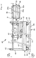
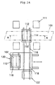
- Fig. 14 is a plan view showing the fourth embodiments according to the present invention, and Figs. 15 and 16 are sectional views along the A-A line in Fig. 14. The status of the dies shown in Figs. 15 and 16 are during operation and during replacement, respectively.
- the die changing apparatus is a die changing apparatus for a plate reduction press that presses the upper and lower dies 102 mounted on the upper and lower sliders 108 and placed vertically opposite each other, towards a slab 101.
- the plate reduction press is represented only by the 4 columns 111.
- the die changing apparatus comprises upper and lower die holders 110 that are fixed to the upper and lower dies 102, respectively, upper and lower die clamps 112 for fixing the die holders 110 in a detachable manner to the sliders 108, and split rails 114 that extend horizontally in the lateral direction (in the direction perpendicular to the paper in this view) of a press line installed beneath the lower die holder 110 and which can be raised and lowered.
- the upper and lower die clamps 112 are provided with a plurality of clamping cylinders 112a (2 cylinders on each of the upper and lower die clamps) that press against the upstream and downstream ends of the die holders 110 (left and right ends in this view) in the press line and put the die holders 110 in close contact with the loading surfaces 108a of the upper and lower sliders 108. It is also possible to form the die holders 110 and the die clamps 112 as an integral unit.
- the rods of the clamping cylinders 112a are extended to push the die holders 110 closely against the loading surfaces 108a of the sliders 108, and at the same time the raising/lowering cylinders 114a for raising and lowering the split rails 114 are retracted and the supporting surfaces (upper surfaces) of the split rails 114 are separated from the lower die holder 110, thereby the upper and lower die holders 110 with their dies are ready for operation.
- the reaction forces when a slab 101 is pressed are transmitted from the dies 102 to the sliders 108 through the loading surfaces 108a.
- the die changing apparatus further comprises changing rails continuing from the split rails 114 with supporting surfaces flush with the supporting surfaces of the raised split rails and extending horizontally outside the press machine, a plurality of shift rails 118 (2 sets in this view) with supporting surfaces flush with the supporting surfaces of the changing rails 116, a sideways shifting apparatus 120 that moves the shift rails 118 in the direction of the press line so that any of the shift rails 118 can be aligned with the changing rails, and a die clamp moving apparatus 122 that slides the upper and lower die holders 110 together with the dies after removal from the die clamps, from the raised split rails 114, to the shift rails 118 via the changing rails 116.
- the sideways shift apparatus 120 comprises a moving base 120b with a plurality of shift rails 118 (2 sets in this view) mounted on the upper surface of the base and guided in the direction of the press line by rails 120a, and a moving cylinder (not illustrated) installed underneath the moving base 120b.
- the die clamp moving apparatus 122 comprises a car, cylinder, etc.
- the shift rails 118 can be installed in either 2 rows (for new and old dies) or 3 rows or more.
- dies are changed using the following steps A through G.
- upper and lower die holders with dies (new and old dies or dies with different dimensions or of different types) placed on a plurality of sets of shift rails 118 can be quickly, easily and automatically replaced using the sideways shift apparatus 120.
- old dies worn or heat-cracked
- new dies unused dies or dies whose surfaces were restructured
- dies of different types corresponding to the thickness of the bar leaving the press, or of different shapes, angles, etc.
- two or more dies can be replaced every time several slabs have been pressed, and the dies cooled during the period when they are not in use (when dies are placed outside the press machine), thereby extending the life of the dies.
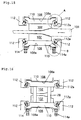
- Fig. 17 is a partial view of another example of the embodiment shown in Fig. 15.
- (A) is a view showing another example of the part A in Fig. 15, and (B) shows another example of the part B in Fig. 15.
- FIG. 17 (A) Another possible configuration is shown in Fig. 17 (A) in which a wedge is moved horizontally by the clamping cylinder 112a to keep the die 102 in place. It is also possible that if the above-mentioned sliding part requires a large force to overcome friction when being moved, wheels can be placed between the rail 114 and the die holder 110 to permit a rolling movement instead of sliding, as shown in Fig. 17 (B).
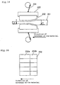
- Fig. 18 is a plan view showing the fifth embodiment of the die changing apparatus according to the present invention.
- the die changing apparatus based on the present invention comprises changing rails 124 that are a continuation of the split rails 114 on the opposite side to the changing rails 116, with supporting surfaces flush with the supporting surfaces of the raised split rails 114 and extending horizontally outside the press machine, and a die changing clamp moving apparatus 126 that slides the upper and lower die holders with another set of dies, located on the changing rails 114, on to the raised split rails.
- the die changing clamp moving apparatus 126 can comprise a car, cylinder, ram drive, etc.
- the other component parts are the same as those of the fourth embodiment shown in Fig. 14.
- replacing dies can be simplified, expedited and automated by using the die changing clamp moving apparatus 26 which can easily and quickly install the upper and lower die holders with another set of dies, located on the changing rails.
- the thickness of a bar can be changed, the gap adjusting apparatus of the press machine can be eliminated, different types of dies can be easily changed and used, dies can be cooled externally to prolong their life, and the thickness of a slab can be maintained uniform at a high temperature because the dies are not cooled with water in the press machine (or the flow of water can be reduced).
- the die changing apparatus and methods for a plate reduction press machine allow the dies in the plate reduction press machine to be replaced easily and quickly, so that the thickness of a bar can be changed, the gap adjusting apparatus of the press machine can be eliminated, different type of dies can be easily replaced and used, dies can be cooled externally and their life can be prolonged, and the dies are not cooled with water in the press machine (or the flow of water can be reduced), therefore the apparatus and the method provides superior advantages such as the capability of maintaining the thickness of a slab evenly at a high temperature.
- Fig. 19 is a view showing the configuration of a press machine using the split dies of the first embodiment according to the present invention.
- the press machine consists of split dies 202 arranged vertically above and below a material 201 to be pressed, die clamps 203 holding the split dies 202 together to form a single body, and a pressing apparatus 204 that applies a pressing load to the split dies 202 via the die clamps 203.
- Fig. 19 schematically shows a crank mechanism as the pressing apparatus 204, another mechanism such as a hydraulic cylinder may also be used.
- Fig. 20 is a view in the direction of the arrows X-X in Fig. 19, showing a plan view of the first embodiment of split dies according to the present invention.
- the dies consist of a plurality of split segments 202 arranged closely to each other in the lateral direction of a material 201 to be pressed.
- 5 split segments 202 are shown, but the plurality of split segments can be adjusted appropriately according to the width of the material 201 to be pressed.
- the planar shape of a split segment 202 in plan view is rectangular, and the surface facing the material 201 to be pressed is configured as a plane 202a parallel to the surface of the material 201 and a sloping surface 202b inclined to the surface of the material 201.
- Fig. 21 shows an example of a passage for cooling water, provided in a split die 202.
- (A) and (B) show a side view and a view in the direction of the arrows Y-Y, respectively.
- the cooling water passage 205 is constructed inside the split die 202, to pass cooling water, and a hose not illustrated is connected to supply the cooling water. Thereby, even when a high-temperature slab etc. is to be pressed, the split die 202 can be maintained at a low temperature, so that the life of the split die 202 can be made longer.
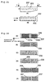
- Fig. 22 shows grooves 206 or raised parts 207 formed on the parallel and sloping surfaces 202a, 202b of the split die 202.
- A is concerned with a case in which a plurality of circular grooves 206 partially superimposed on each other, are formed on the parallel and sloping surfaces 202a, 202b.
- B is a case in which a plurality of straight grooves 206 are formed on the parallel and sloping surfaces 202a, 202b in the direction of movement of the material 201 to be pressed.
- (C) represents a case in which a plurality of straight grooves 206 aligned in the direction perpendicular to the direction in which the material 201 to be pressed is moved are formed on the parallel and sloping surfaces 202a, 202b.
- (D) a plurality of straight grooves 206 in the direction of movement of the material 201 to be pressed are formed on the parallel surface 202a, and straight grooves 206 in the direction perpendicular to the direction of movement of the material 201 to be pressed are formed on the sloping surface 202b.
- (E) is a case in which a diagonal check pattern of grooves 206 is formed on the parallel and sloping surfaces 202a, 202b.
- (F) shows many square raised portions 207 formed on the parallel and sloping surfaces 202a, 202b.
- grooves 206 or raised portions 207 slippage during pressing, between the dies and the material being pressed 201, is reduced.
- a volume of material proportional to the reduction in thickness must be displaced (this is called the deformation flow of the material).
- These grooves 206 or raised portions 207 can control the direction of this deformation flow.
- Fig. 23 is a view in the direction of the arrows X-X in Fig. 19 and shows the second embodiment of the split dies 202.
- the surfaces of a die 202 in contact with adjacent dies are inclined to the direction of movement (longitudinal direction) of the material 201 to be pressed, and this is a difference from the split dies 202 of the first embodiment shown in Fig. 20.
- the cooling water passages 205 shown in Fig. 21 are provided also in the split dies 202 of the second embodiment of the present invention, on which the grooves 206 or raised portions 207 shown in Fig.
Landscapes
- Engineering & Computer Science (AREA)
- Mechanical Engineering (AREA)
- Mounting, Exchange, And Manufacturing Of Dies (AREA)
- Forging (AREA)
- Press Drives And Press Lines (AREA)
- Bending Of Plates, Rods, And Pipes (AREA)
- Photosensitive Polymer And Photoresist Processing (AREA)
- Manufacture Or Reproduction Of Printing Formes (AREA)
- Printing Methods (AREA)
Applications Claiming Priority (7)
| Application Number | Priority Date | Filing Date | Title |
|---|---|---|---|
| JP32466897 | 1997-11-26 | ||
| JP32466897A JP3991134B2 (ja) | 1997-11-26 | 1997-11-26 | 板厚圧下プレス装置 |
| JP00293398A JP3991139B2 (ja) | 1998-01-09 | 1998-01-09 | プレス金型 |
| JP293398 | 1998-01-09 | ||
| JP16654798 | 1998-06-15 | ||
| JP16654798A JP4072653B2 (ja) | 1998-06-15 | 1998-06-15 | 板厚圧下プレスの金型交換装置とその方法 |
| PCT/JP1998/005063 WO1999026737A1 (en) | 1997-11-26 | 1998-11-10 | Apparatus and method for changing metal molds for plate thickness reducing presses, and press metal die |
Publications (3)
| Publication Number | Publication Date |
|---|---|
| EP0955104A1 true EP0955104A1 (de) | 1999-11-10 |
| EP0955104A4 EP0955104A4 (de) | 2003-06-11 |
| EP0955104B1 EP0955104B1 (de) | 2005-01-26 |
Family
ID=27275598
Family Applications (1)
| Application Number | Title | Priority Date | Filing Date |
|---|---|---|---|
| EP98951769A Expired - Lifetime EP0955104B1 (de) | 1997-11-26 | 1998-11-10 | Vorrichtung und verfahren zum wechseln von metallpressformen für plattendickereduzierende pressen |
Country Status (10)
| Country | Link |
|---|---|
| US (1) | US6200245B1 (de) |
| EP (1) | EP0955104B1 (de) |
| KR (1) | KR100550717B1 (de) |
| CN (1) | CN1123405C (de) |
| AT (1) | ATE287770T1 (de) |
| BR (1) | BR9807008A (de) |
| DE (1) | DE69828775T2 (de) |
| ID (1) | ID22030A (de) |
| TR (1) | TR199901780T1 (de) |
| WO (1) | WO1999026737A1 (de) |
Cited By (2)
| Publication number | Priority date | Publication date | Assignee | Title |
|---|---|---|---|---|
| US6200245B1 (en) | 1997-11-26 | 2001-03-13 | Ishikawajima-Harima Heavy Industries Co., Ltd. | Apparatus and method for changing dies |
| CN117943508A (zh) * | 2024-03-26 | 2024-04-30 | 溧阳市金昆锻压有限公司 | 一种齿轮锻压用定位机构 |
Families Citing this family (46)
| Publication number | Priority date | Publication date | Assignee | Title |
|---|---|---|---|---|
| US6676587B2 (en) * | 2001-09-13 | 2004-01-13 | Hallmark Cards Incorporated | Integrated emboss module |
| KR100651652B1 (ko) * | 2004-11-09 | 2006-12-07 | 삼표이앤씨 주식회사 | 레일 단부 성형장치 및 성형방법 |
| US7220222B2 (en) * | 2005-01-19 | 2007-05-22 | Multi-Shifter Inc. | Cart for die transportation |
| US8096156B2 (en) * | 2006-12-22 | 2012-01-17 | Crown Packaging Technology, Inc. | Forming of metal container bodies |
| US7726166B2 (en) * | 2007-03-07 | 2010-06-01 | Gns Co., Ltd. | Multi-step press system |
| US7562551B2 (en) * | 2007-03-07 | 2009-07-21 | Gns Co., Ltd. | Press die set for a multi-step press system |
| US8006826B2 (en) * | 2008-03-28 | 2011-08-30 | Crown Packagin Technology, Inc. | Star wheel with vacuum capability for retaining conveyed articles |
| CN101648428B (zh) * | 2009-09-11 | 2012-01-18 | 裕克施乐塑料制品(太仓)有限公司 | 一种侧面换模具的方法 |
| DE102010009536A1 (de) * | 2010-02-26 | 2011-09-01 | Cfs Germany Gmbh | Verfahren zum Wechsel des Ober- und Unterwerkzeugs einer Verpackungsmaschine |
| CN101972833A (zh) * | 2010-09-29 | 2011-02-16 | 曾奇夫 | 一种模具装置 |
| DE102011101051A1 (de) * | 2011-05-10 | 2012-11-15 | Multivac Sepp Haggenmüller Gmbh & Co. Kg | Werkzeugwechseleinrichtung |
| CN102975055B (zh) * | 2011-09-07 | 2015-03-18 | 朱华丰 | 一种模具压板 |
| JP5962283B2 (ja) * | 2011-10-25 | 2016-08-03 | Jfeスチール株式会社 | 熱間スラブの形状調節方法 |
| DE102012003830A1 (de) * | 2012-02-29 | 2013-08-29 | Gea Cfs Germany Gmbh | Verpackungsmaschine mit einem auswechselbaren Werkzeug |
| US10335848B2 (en) * | 2012-07-19 | 2019-07-02 | Miwon Precision Ind. Co., Ltd. | Press-molded article manufacturing system and method for changing press molds and grippers |
| CN102861881B (zh) * | 2012-10-24 | 2014-07-16 | 无锡蠡湖叶轮制造有限公司 | 制芯机模具切换车 |
| CN103331366A (zh) * | 2013-06-21 | 2013-10-02 | 太仓市旭冉机械有限公司 | 一种新型五金件自动夹紧成型夹具 |
| CN103753257B (zh) * | 2013-12-17 | 2015-12-02 | 重庆交通大学 | 可调组合夹具 |
| DE102013021055A1 (de) | 2013-12-18 | 2015-06-18 | Newfrey Llc | Wechselmatrizen-Übergabestation, Fügewerkzeugsystem und Fügeverfahren |
| TWI648126B (zh) * | 2014-01-27 | 2019-01-21 | Lns Management Sa | 用於棒材進給系統的棒材導向單元 |
| US9828128B1 (en) | 2014-12-17 | 2017-11-28 | X Development Llc | On-demand protective structures for packaging items in a container |
| US9840347B1 (en) | 2014-12-17 | 2017-12-12 | X Development LLX | Adhering modular elements for packaging structures |
| CN105251766B (zh) * | 2015-10-23 | 2017-06-27 | 徐州欧普莱斯工业机械有限公司 | 一种金属丝碾压装置 |
| CN105855958B (zh) * | 2016-05-30 | 2018-10-12 | 瑞立集团瑞安汽车零部件有限公司 | 通用型气动自锁夹紧夹具 |
| CN106584765A (zh) * | 2016-11-18 | 2017-04-26 | 江苏智石科技有限公司 | 一种自适应车床高度的换模台车 |
| EP3573806A4 (de) | 2017-01-30 | 2019-12-11 | Ortho-Space Ltd. | Bearbeitungsmaschine und verfahren zur verarbeitung von tauchgeformten artikeln |
| CN107838299B (zh) * | 2017-10-25 | 2019-11-08 | 合肥常青机械股份有限公司 | 一种快速换模工装 |
| CN107952875B (zh) * | 2017-12-04 | 2024-05-03 | 苏州三屹晨光自动化科技有限公司 | 一种带翻转脱模装置的成型机 |
| CN108407375A (zh) * | 2018-05-10 | 2018-08-17 | 枣阳市天亿达精密工具有限公司 | 鼓式刹车片全自动压制成型装置 |
| DE102019000320A1 (de) * | 2018-12-21 | 2020-06-25 | Tönnjes Isi Patent Holding Gmbh | Verfahren und Vorrichtung zum Prägen von Kennzeichen, insbesondere Kraftfahrzeugkennzeichen |
| CN110216192B (zh) * | 2019-05-28 | 2024-06-07 | 东莞智富五金制品有限公司 | 一种快速换模的冲压装置 |
| CN110523897A (zh) * | 2019-08-09 | 2019-12-03 | 昆山佰奥智能装备股份有限公司 | 多发导线芯片同步铆压扣合机构 |
| JP7516116B2 (ja) | 2020-06-03 | 2024-07-16 | 日本発條株式会社 | ロードビームを有するディスク装置用サスペンション |
| CN112007985A (zh) * | 2020-09-14 | 2020-12-01 | 江苏鸿基金属制品有限公司 | 一种汽车模金属冲压零件的翻孔加工模具 |
| CN113399568B (zh) * | 2021-06-25 | 2023-02-10 | 长春一汽富维汽车零部件股份有限公司 | 一种车轮滚型模具换模的工装线和方法 |
| CN113459580B (zh) * | 2021-07-13 | 2023-03-31 | 靖江市斯坦普模具有限公司 | 一种生产车辆发动机仓高温隔热罩用模具 |
| CN113798348A (zh) * | 2021-09-26 | 2021-12-17 | 中国重型机械研究院股份公司 | 一种分级砧座机构及方法 |
| CN113895082B (zh) * | 2021-10-15 | 2023-11-14 | 安徽佰特包装制品股份有限公司 | 一种纸箱压痕设备 |
| CN114000377A (zh) * | 2021-10-29 | 2022-02-01 | 珠海格力智能装备有限公司 | 换模结构及具有其的模具组件 |
| CN114054565B (zh) * | 2021-11-16 | 2024-04-09 | 重庆晋川精密五金有限公司 | 一种产品料带自动冲压设备 |
| CN114713708B (zh) * | 2022-06-07 | 2022-08-26 | 徐州市富昌制药机械有限公司 | 一种具有调节功能的冲孔机 |
| CN115156394B (zh) * | 2022-09-05 | 2022-11-18 | 西安成立航空制造有限公司 | 一种航空航天飞机用铝合金变曲率多点成型设备 |
| CN116037660B (zh) * | 2023-03-08 | 2023-11-14 | 江苏甬金金属科技有限公司 | 一种附带雾化油清理功能的硅钢片冷轧装置 |
| CN116494591A (zh) * | 2023-04-12 | 2023-07-28 | 科达制造股份有限公司 | 辊压机及辊压机内支撑板更换方法 |
| CN116945425B (zh) * | 2023-07-24 | 2026-04-21 | 克劳斯玛菲机械(中国)有限公司 | 一种换模装置 |
| CN118002672A (zh) * | 2024-04-08 | 2024-05-10 | 福建祥鑫新材料科技有限公司 | 一种自动化铝合金型材挤压装置及方法 |
Family Cites Families (22)
| Publication number | Priority date | Publication date | Assignee | Title |
|---|---|---|---|---|
| GB1122347A (en) * | 1966-05-11 | 1968-08-07 | Kocks Wermelskirchen Gmbh | Improvements in stretch forging machines |
| FR1516969A (fr) * | 1967-01-30 | 1968-02-05 | Emidecau Soc | Presse à trois postes du type à plateaux basculants |
| US3559522A (en) * | 1969-01-28 | 1971-02-02 | Manco Mfg Co | Interchangeable die units for hydraulic presses |
| US3841141A (en) * | 1973-07-09 | 1974-10-15 | S Rachwal | Die changing apparatus |
| JPS5328553A (en) * | 1976-08-31 | 1978-03-16 | Amada Co Ltd | Device for carryyin and out housing metal mold for press device |
| JPS558355A (en) * | 1978-07-05 | 1980-01-21 | Hitachi Ltd | Press forming method |
| JPS57106403A (en) | 1980-12-22 | 1982-07-02 | Kawasaki Steel Corp | Continuous hot rolling installation |
| JPS57106409A (en) | 1980-12-23 | 1982-07-02 | Kawasaki Steel Corp | Continuous hot rolling equipment |
| JPS5985305A (ja) | 1982-11-06 | 1984-05-17 | Kawasaki Steel Corp | 連続熱間圧延ライン |
| JPS5992103A (ja) | 1982-11-18 | 1984-05-28 | Kawasaki Steel Corp | ホツトストリツプの圧延方法 |
| US4614108A (en) * | 1985-04-12 | 1986-09-30 | Tek-Matik, Inc. | Die cart |
| JPS6390303A (ja) | 1986-10-03 | 1988-04-21 | Sumitomo Metal Ind Ltd | 熱間圧延設備 |
| JP2580265B2 (ja) | 1988-06-30 | 1997-02-12 | 大阪瓦斯株式会社 | 複合不織布 |
| JP2705172B2 (ja) | 1988-12-27 | 1998-01-26 | 石川島播磨重工業株式会社 | 走間サイジングプレス装置 |
| JPH0489190A (ja) | 1990-07-31 | 1992-03-23 | Nippondenso Co Ltd | 絶縁電線と端子との接合方法 |
| DE4029429A1 (de) * | 1990-09-17 | 1992-03-19 | Schloemann Siemag Ag | Vorrichtung zum wechseln der presswerkzeuge einer stauchpresse |
| US5366431A (en) * | 1990-12-13 | 1994-11-22 | Uniflo Conveyor, Inc. | Automated press brake die transfer system |
| JPH06165803A (ja) | 1992-11-30 | 1994-06-14 | Asahi Kogyo Kk | 気泡発生装置 |
| JP2730845B2 (ja) * | 1993-06-07 | 1998-03-25 | 川崎製鉄株式会社 | サイジングプレス装置及びその金型交換方法 |
| US5913761A (en) * | 1993-06-28 | 1999-06-22 | Komatsu Ltd. | Punch press |
| ID22030A (id) | 1997-11-26 | 1999-08-26 | Ishikawajima Harima Heavy Ind | Peralatan dan metode untuk merubah cetakan dan pencetak tekanan untuk mesin penekan yang mereduksi pelat |
| JPH11249346A (ja) | 1998-02-27 | 1999-09-17 | Hitachi Koki Co Ltd | 連続紙の記録装置 |
-
1998
- 1998-11-10 ID IDW990744A patent/ID22030A/id unknown
- 1998-11-10 TR TR1999/01780T patent/TR199901780T1/xx unknown
- 1998-11-10 AT AT98951769T patent/ATE287770T1/de not_active IP Right Cessation
- 1998-11-10 CN CN98802004A patent/CN1123405C/zh not_active Expired - Fee Related
- 1998-11-10 DE DE69828775T patent/DE69828775T2/de not_active Expired - Lifetime
- 1998-11-10 BR BR9807008-8A patent/BR9807008A/pt not_active IP Right Cessation
- 1998-11-10 EP EP98951769A patent/EP0955104B1/de not_active Expired - Lifetime
- 1998-11-10 US US09/355,198 patent/US6200245B1/en not_active Expired - Fee Related
- 1998-11-10 WO PCT/JP1998/005063 patent/WO1999026737A1/ja not_active Ceased
- 1998-11-10 KR KR1019997006695A patent/KR100550717B1/ko not_active Expired - Fee Related
Cited By (2)
| Publication number | Priority date | Publication date | Assignee | Title |
|---|---|---|---|---|
| US6200245B1 (en) | 1997-11-26 | 2001-03-13 | Ishikawajima-Harima Heavy Industries Co., Ltd. | Apparatus and method for changing dies |
| CN117943508A (zh) * | 2024-03-26 | 2024-04-30 | 溧阳市金昆锻压有限公司 | 一种齿轮锻压用定位机构 |
Also Published As
| Publication number | Publication date |
|---|---|
| ATE287770T1 (de) | 2005-02-15 |
| KR20000070458A (ko) | 2000-11-25 |
| EP0955104B1 (de) | 2005-01-26 |
| DE69828775T2 (de) | 2005-07-14 |
| DE69828775D1 (de) | 2005-03-03 |
| TR199901780T1 (en) | 2000-02-21 |
| US6200245B1 (en) | 2001-03-13 |
| CN1244144A (zh) | 2000-02-09 |
| BR9807008A (pt) | 2000-03-14 |
| WO1999026737A1 (en) | 1999-06-03 |
| CN1123405C (zh) | 2003-10-08 |
| KR100550717B1 (ko) | 2006-02-08 |
| EP0955104A4 (de) | 2003-06-11 |
| ID22030A (id) | 1999-08-26 |
Similar Documents
| Publication | Publication Date | Title |
|---|---|---|
| US6200245B1 (en) | Apparatus and method for changing dies | |
| EP0593709B1 (de) | Walzgeruest fuer walzwerke mit drei oder mehr verstellbaren angetriebenen walzen | |
| JP4988763B2 (ja) | ロールの交換/搬送をするための装置 | |
| US5735157A (en) | Roll width adjusting device | |
| US5392627A (en) | Leveling machine for metal sheet and strip | |
| JP2004520172A (ja) | 連続鋳造設備の鋳片ガイド並びにロールセグメントの圧下方法 | |
| KR101157661B1 (ko) | 금속 밴드의 템퍼 롤링 장치와, 금속 밴드의 템퍼 롤링을개선하는 방법 | |
| US3367162A (en) | Apparatus for reducing slab width | |
| JP2008200717A (ja) | 条鋼圧延用の圧延機 | |
| JPH0241361B2 (de) | ||
| JP4072653B2 (ja) | 板厚圧下プレスの金型交換装置とその方法 | |
| US3504517A (en) | Apparatus for dismounting and remounting the rolls in a four-high rolling mill | |
| JP3241569B2 (ja) | エッジング圧延機のガイド装置 | |
| CN219616388U (zh) | 一种小型二辊热轧机的快速换辊结构 | |
| RU2237532C2 (ru) | Устройство для регулируемого воздействия на силы трения между направляющими и упорными поверхностями опорных подушек валков, установленных в проемах стоек прокатных клетей | |
| JP2730845B2 (ja) | サイジングプレス装置及びその金型交換方法 | |
| JP2005262279A (ja) | スキンパスミルのワークロール組替装置及び組替方法 | |
| JPH11169923A (ja) | 圧延機のパスライン調整装置 | |
| US3695080A (en) | System for the replacement of rolling-mill rolls | |
| JP2726215B2 (ja) | ユニバーサル圧延機 | |
| SU1588455A1 (ru) | Устройство дл смены валков прокатной клети кварто | |
| US20090038771A1 (en) | Casting Roll Moving Apparatus of Twin Roll Type Continuous Strip Casting Process | |
| JPH11156401A (ja) | 板厚圧下プレス装置 | |
| CN121156084A (zh) | 一种平整机工作辊的换辊装置 | |
| JP2658373B2 (ja) | 水平対向型プレスの金型交換方法及び装置 |
Legal Events
| Date | Code | Title | Description |
|---|---|---|---|
| PUAI | Public reference made under article 153(3) epc to a published international application that has entered the european phase |
Free format text: ORIGINAL CODE: 0009012 |
|
| AK | Designated contracting states |
Kind code of ref document: A1 Designated state(s): AT DE FR GB IT |
|
| 17P | Request for examination filed |
Effective date: 19991126 |
|
| A4 | Supplementary search report drawn up and despatched |
Effective date: 20030428 |
|
| RIC1 | Information provided on ipc code assigned before grant |
Ipc: 7B 21J 1/04 B Ipc: 7B 21B 15/00 A |
|
| 17Q | First examination report despatched |
Effective date: 20031215 |
|
| GRAP | Despatch of communication of intention to grant a patent |
Free format text: ORIGINAL CODE: EPIDOSNIGR1 |
|
| RTI1 | Title (correction) |
Free format text: APPARATUS AND METHOD FOR CHANGING METAL MOLDS FOR PLATE THICKNESS REDUCING PRESSES |
|
| RAP1 | Party data changed (applicant data changed or rights of an application transferred) |
Owner name: JFE STEEL CORPORATION Owner name: ISHIKAWAJIMA-HARIMA HEAVY INDUSTRIES CO., LTD. |
|
| GRAS | Grant fee paid |
Free format text: ORIGINAL CODE: EPIDOSNIGR3 |
|
| RAP1 | Party data changed (applicant data changed or rights of an application transferred) |
Owner name: JFE STEEL CORPORATION Owner name: ISHIKAWAJIMA-HARIMA HEAVY INDUSTRIES CO., LTD. |
|
| GRAA | (expected) grant |
Free format text: ORIGINAL CODE: 0009210 |
|
| AK | Designated contracting states |
Kind code of ref document: B1 Designated state(s): AT DE FR GB IT |
|
| REG | Reference to a national code |
Ref country code: GB Ref legal event code: FG4D |
|
| REF | Corresponds to: |
Ref document number: 69828775 Country of ref document: DE Date of ref document: 20050303 Kind code of ref document: P |
|
| PLBE | No opposition filed within time limit |
Free format text: ORIGINAL CODE: 0009261 |
|
| STAA | Information on the status of an ep patent application or granted ep patent |
Free format text: STATUS: NO OPPOSITION FILED WITHIN TIME LIMIT |
|
| ET | Fr: translation filed | ||
| 26N | No opposition filed |
Effective date: 20051027 |
|
| PGFP | Annual fee paid to national office [announced via postgrant information from national office to epo] |
Ref country code: AT Payment date: 20091111 Year of fee payment: 12 |
|
| PGFP | Annual fee paid to national office [announced via postgrant information from national office to epo] |
Ref country code: IT Payment date: 20091114 Year of fee payment: 12 Ref country code: GB Payment date: 20091104 Year of fee payment: 12 Ref country code: FR Payment date: 20091123 Year of fee payment: 12 |
|
| GBPC | Gb: european patent ceased through non-payment of renewal fee |
Effective date: 20101110 |
|
| REG | Reference to a national code |
Ref country code: FR Ref legal event code: ST Effective date: 20110801 |
|
| PG25 | Lapsed in a contracting state [announced via postgrant information from national office to epo] |
Ref country code: AT Free format text: LAPSE BECAUSE OF NON-PAYMENT OF DUE FEES Effective date: 20101110 |
|
| PG25 | Lapsed in a contracting state [announced via postgrant information from national office to epo] |
Ref country code: FR Free format text: LAPSE BECAUSE OF NON-PAYMENT OF DUE FEES Effective date: 20101130 |
|
| PG25 | Lapsed in a contracting state [announced via postgrant information from national office to epo] |
Ref country code: GB Free format text: LAPSE BECAUSE OF NON-PAYMENT OF DUE FEES Effective date: 20101110 |
|
| PG25 | Lapsed in a contracting state [announced via postgrant information from national office to epo] |
Ref country code: IT Free format text: LAPSE BECAUSE OF NON-PAYMENT OF DUE FEES Effective date: 20101110 |
|
| PGFP | Annual fee paid to national office [announced via postgrant information from national office to epo] |
Ref country code: DE Payment date: 20121107 Year of fee payment: 15 |
|
| REG | Reference to a national code |
Ref country code: DE Ref legal event code: R119 Ref document number: 69828775 Country of ref document: DE Effective date: 20140603 |
|
| PG25 | Lapsed in a contracting state [announced via postgrant information from national office to epo] |
Ref country code: DE Free format text: LAPSE BECAUSE OF NON-PAYMENT OF DUE FEES Effective date: 20140603 |