EP0955414A2 - Dispositif pour fixer des mats pour des feux de circulation ou similaires - Google Patents
Dispositif pour fixer des mats pour des feux de circulation ou similaires Download PDFInfo
- Publication number
- EP0955414A2 EP0955414A2 EP99108898A EP99108898A EP0955414A2 EP 0955414 A2 EP0955414 A2 EP 0955414A2 EP 99108898 A EP99108898 A EP 99108898A EP 99108898 A EP99108898 A EP 99108898A EP 0955414 A2 EP0955414 A2 EP 0955414A2
- Authority
- EP
- European Patent Office
- Prior art keywords
- dowel
- hole
- arrangement according
- sleeve element
- mast
- Prior art date
- Legal status (The legal status is an assumption and is not a legal conclusion. Google has not performed a legal analysis and makes no representation as to the accuracy of the status listed.)
- Granted
Links
- 230000006378 damage Effects 0.000 claims description 8
- 230000007704 transition Effects 0.000 claims description 4
- 239000002184 metal Substances 0.000 claims description 2
- 238000000034 method Methods 0.000 claims description 2
- 230000003068 static effect Effects 0.000 claims description 2
- 238000003780 insertion Methods 0.000 claims 1
- 230000037431 insertion Effects 0.000 claims 1
- 238000011161 development Methods 0.000 description 6
- 230000018109 developmental process Effects 0.000 description 6
- 208000027418 Wounds and injury Diseases 0.000 description 2
- 238000006073 displacement reaction Methods 0.000 description 2
- 230000003116 impacting effect Effects 0.000 description 2
- 208000014674 injury Diseases 0.000 description 2
- 229910000831 Steel Inorganic materials 0.000 description 1
- 230000006978 adaptation Effects 0.000 description 1
- 238000005452 bending Methods 0.000 description 1
- 230000001419 dependent effect Effects 0.000 description 1
- 230000002349 favourable effect Effects 0.000 description 1
- 238000007373 indentation Methods 0.000 description 1
- 238000010008 shearing Methods 0.000 description 1
- 239000010959 steel Substances 0.000 description 1
- 230000003746 surface roughness Effects 0.000 description 1
Images

Classifications
-
- E—FIXED CONSTRUCTIONS
- E04—BUILDING
- E04H—BUILDINGS OR LIKE STRUCTURES FOR PARTICULAR PURPOSES; SWIMMING OR SPLASH BATHS OR POOLS; MASTS; FENCING; TENTS OR CANOPIES, IN GENERAL
- E04H12/00—Towers; Masts or poles; Chimney stacks; Water-towers; Methods of erecting such structures
- E04H12/22—Sockets or holders for poles or posts
- E04H12/2253—Mounting poles or posts to the holder
- E04H12/2261—Mounting poles or posts to the holder on a flat base
-
- E—FIXED CONSTRUCTIONS
- E01—CONSTRUCTION OF ROADS, RAILWAYS, OR BRIDGES
- E01F—ADDITIONAL WORK, SUCH AS EQUIPPING ROADS OR THE CONSTRUCTION OF PLATFORMS, HELICOPTER LANDING STAGES, SIGNS, SNOW FENCES, OR THE LIKE
- E01F9/00—Arrangement of road signs or traffic signals; Arrangements for enforcing caution
- E01F9/60—Upright bodies, e.g. marker posts or bollards; Supports for road signs
- E01F9/658—Upright bodies, e.g. marker posts or bollards; Supports for road signs characterised by means for fixing
- E01F9/673—Upright bodies, e.g. marker posts or bollards; Supports for road signs characterised by means for fixing for holding sign posts or the like
- E01F9/685—Subsoil means, e.g. foundations
-
- E—FIXED CONSTRUCTIONS
- E02—HYDRAULIC ENGINEERING; FOUNDATIONS; SOIL SHIFTING
- E02D—FOUNDATIONS; EXCAVATIONS; EMBANKMENTS; UNDERGROUND OR UNDERWATER STRUCTURES
- E02D27/00—Foundations as substructures
- E02D27/32—Foundations for special purposes
- E02D27/42—Foundations for poles, masts or chimneys
Definitions
- the invention relates to mounting arrangements for masts, for example, traffic lights or traffic signs are attached.
- masts are currently attached with the help of dowels to concrete blocks that are present in the ground, or they are in concrete blocks, for. B. Foundations, concreted. Since the masts for traffic lights, sign bridges or the like are in the immediate vicinity of the roadway, it often happens that a car drives against the mast. In the case of smaller vehicles, for example cars, there is a risk that the vehicle will be severely damaged, with the risk of injury to the occupants. If, on the other hand, a heavier vehicle drives against such a mast, for example a truck, either the dowels are often torn out of the concrete block or this itself is torn out of the ground.
- the mast attachment cannot be repaired by replacing the dowels, but must be made again.
- the same applies to masts to which other objects are attached provided that the masts are in the area of the road are located. For example, this also includes the masts for lamps.
- the invention has for its object to improve the attachment of masts in terms of safety and damage.
- the mast attachment should be able to be repaired simply by replacing the dowels after a vehicle has impacted the mast.
- the invention proposes a fastening arrangement with the features of claim 1. Further developments of the invention are the subject of the dependent claims, the wording of which, like the wording of the abstract, is made by reference to the content of the description.
- the fastening arrangement is usually carried out by means of dowels which are widened. If the expansion of the dowel is done by moving an expansion body into the dowel sleeve, the dowel can be designed so that the pretensioning force required for the correct attachment of the mast is achieved when the expansion body has not yet been completely moved into the dowel sleeve is.
- the dowel rod which can be, for example, a screw bolt or a threaded rod, is screwed onto a nut is something is pulled out in the direction of action of the dowel. If the load remains in a frame that does not yet fully expand the dowel, the nut can be tightened after removal of the load, so that the attachment can be restored.
- This possibility of the dowel giving way means that the mast also dodges somewhat, so that damage to the motor vehicle that has been driven against the mast can be kept within limits and the risk of injury to the occupants is low.
- the dowel is designed in such a way that the sleeve element detaches from the wall of the hole in the axial direction when a certain even higher pull-out force is exceeded. In this way, a threshold can be set up which, when exceeded, results in a further movement of the dowel rod.
- the sleeve element has a stop acting in the axial direction for the expanding body. This stop can serve to limit the movement of the expansion body relative to the sleeve element, so that a further increasing pull-out force then occurs the connection between the dowel sleeve and the wall of the hole acts.
- the sleeve element and / or the wall of the hole has at least one projection which is pressed into the other element when the dowel is widened.
- the projection is designed such that it is sheared off when a certain pull-out force is exceeded. If the projection is attached to the outside of the dowel sleeve, this shearing leads to the fact that a new dowel can later be inserted into the hole, which has the same function as the first dowel.
- the hole is designed in such a way that it has a constriction in the region of its outer end which is dimensioned in this way is that it allows the unexpanded dowel to be inserted.
- the invention proposes that the narrowing can be dimensioned such that it does not allow the expanded dowel to be pulled out. In this way, a further threshold can be set up, which is effective when the pull-out force is even higher.
- the narrowing at the end of the hole has a funnel-like transition to the cylindrical part of the hole.
- This funnel-shaped transition also makes it possible to remove the dowel again when the expansion body is pushed back by holding the sleeve in place. The funnel shape then allows the sleeve to narrow so that it can be pulled out.
- the sleeve element has a device on which it can be held from the outside of the hole. This holding on makes sense if you want to push the expander back, then pull the sleeve element and then the expander out of the hole.
- the invention makes it possible to design the fastening arrangement so that not only is the load for the occupant of a motor vehicle kept within reasonable limits, which drives against the mast, but also gives the possibility of fastening in almost all cases by exchanging the dowels renew.
- the hole into which the dowel is inserted can be formed, for example, by a cavity in a concrete block. It is also possible for the hole to be formed through the inside of a metal tube.
- the invention proposes to use several holes, each with a dowel, for fastening masts.
- the invention also proposes a dowel for fastening masts or the like, which is designed as described in the present application.
- the invention proposes the use of a dowel as described herein for fastening masts for traffic lights, signs, sign bridges or the like.
- the dowel be fastened with a pretensioning force which is dimensioned such that the fastening remains intact if a certain load is placed on the mast. If this load is exceeded, the expansion body of the dowel is moved further into the dowel sleeve while moving the dowel rod. This leads to the mentioned flexibility of the fastening and thus the mast, which thereby converts part of the impact energy of the motor vehicle into the deformation of the dowel.
- the mast can be properly re-attached by retightening the nuts on the dowels. If the load is even higher, the dowel sleeve is moved relative to the wall of the hole.
- the loads at which the further movement of the dowel by pulling the expansion element into the sleeve element and then sliding of the sleeve element in the hole, and the load at which the dowel rod tears, are determined so that on the one hand the fastening in many cases by retightening the nuts can be repaired, and on the other hand, the occupants of a vehicle causing the load are not harmed.
- the invention also proposes a method with the features mentioned in claim 21.
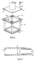
- Fig. 1 shows an exploded perspective of the manner in which a mast 1 is attached.
- the mast 1 is welded onto a plate 2.
- the steel plate 2 has a square shape and increases the footprint compared to your mast 1. Their thickness can be chosen so that the plate 2 does not deform significantly under load. However, the plate can also be designed so that it bends under a certain load (flexible plate).
- In the area of each corner 3 of the plate 2 there is a hole 4.
- the plate 2 is fastened to the frame 6 shown below in FIG. 1 with the aid of dowels 5, only one of which is shown in FIG. 1. This frame 6 is concreted.
- the tubes 7 contain four mutually parallel tubes 7 to be arranged, the inside diameter of which is smaller in the area of the upper end than along the remaining length, the widening taking place in a funnel shape.
- the tubes 7 are welded in the corners of a frame 8 in the region of their upper ends.
- the frame contains four angle profiles 9 which are butt welded together in the region of their ends.
- the corners are reinforced by inclined webs 10.
- the tubes 7 are connected to one another by angle profiles 12, these angle profiles likewise forming a frame.
- This frame 6 is concreted so that the upper level of the horizontal flanges of the Profiles 9 and the ends of the tubes 7 is formed, is flush with the top of the resulting concrete block.
- the plate 2 is placed on the frame 6 and fastened to the frame or the pipes 7 with the aid of the dowels 5 proposed by the invention.
- a pull-out force is calculated until the mast should stop.
- the dowel is selected so that it causes this pull-out force with a certain tightening torque for the given diameter of the tube 7.
- the dowel is then inserted into the tube or first fixed to the plate 2 with its dowel rod and then inserted into the tube 7.
- the mast is brought into the final position and provisionally fixed. The dowel then assumes the position shown schematically in FIG. 2.
- the dowel contains a dowel sleeve 13, which is designed, for example, by longitudinal slots in such a way that it can be expanded by an expansion body 14.
- the cone angle of the expansion body 14 and the dowel sleeve 13 can be chosen so small that the spreading force is slowly increased by a large movement.
- a dowel rod 15 is connected to the expansion body 14, the axial movement of which pulls the expansion body 14 into the sleeve element 13 of the dowel.
- the dowel rod 15 can be a threaded rod, onto which a nut 16 is screwed from the opposite side of the plate 2.
- the dowel rod 15 could be a screw that has a head on the outside of the plate 2 has and which is screwed into an internal thread of the expansion body 14.
- the dowel sleeve 13 contains at its end facing the outside of the tube 17 a plate 18 provided with a through opening, which thus forms a base for the sleeve element 13.
- the stop 23 can also be achieved by narrowing the sleeve 13 at the sleeve end, for example by compressing or bending the sleeve and / or increasing the wall thickness.
- the sleeve element 13 contains on its outside at least one rib 19 which extends wholly or partly over the circumference and which can have a sharp edge 20.
- Fig. 2 shows the dowel in an unexpanded state. If the nut 16 is now rotated, the expansion body 14 is drawn into the sleeve element 13, which leads to the rib 19 being pressed into the inner surface 21 of the tube 7. This indentation can be facilitated if the rib 19 has a sharp edge 20. The nut 16 is further rotated until the tightening torque mentioned above is reached. This situation is shown in Fig. 3. Here the rib 19 has buried itself deep into the wall 21 of the tube 7. In this position corresponding to the maximum desired load on the mast, the expansion body 14 has not yet moved completely into the sleeve element 13, but preferably only by less than half the possible path.
- the load on the mast 1 is significantly lower than this corresponds to the tightening torque of the anchor. This also applies if a vehicle hits the mast at low speed. Now occurs a case where the Load on the mast 1 exceeds this limit load, for example because a motor vehicle drives to the mast at a higher speed, then a pulling force occurs on the dowel rod 15, which leads to a displacement of the pull rod 15. This means that the expansion body 14 is moved further into the sleeve element 13, since the sleeve element 13 is connected to the tube 7 in a non-displaceable manner by the projection 19. This further movement may lead to the position shown in FIG. 4, where the expander body 14 rests with its front end face 22 on the plate 18 forming a stop.
- the mast can now be released from the attachment to the frame 6 by unscrewing the nut 16 or the screw 17. Then, with the aid of a device, not shown, the sleeve element 13 can be held in place and the expansion body 14 can be pushed further down into the tube 7. Then it becomes possible to pull the sleeve element 13, which is no longer expanded by the expansion body, outwards through the front end 25 of the tube 7. Now a new dowel can be inserted into the tube 7 so that the old mast can now be re-attached or replaced with a new mast. The only small restriction must be made that the initial positioning of your new dowel must be chosen so that its rib 19 is not located at exactly the same location as the rib 19 remaining in the tube.
- the sleeve element 13 with the expansion body 14 inserted in it remains attached to the constriction 25 which is formed at the outer end 24 of the tube 7.
- the transition 26 between your cylindrical part of the tube 7 and the constriction 25 is conical or funnel-shaped.
- the dowel can be removed in the same or a similar way as in FIG. 5.
- the dangers for the occupants of motor vehicles are reduced and at the same time there is the possibility of reusing the frame 6, which remains unchanged in your concrete block, for fastening the mast.
- the dowels can be removed from your frame 6 as described above and a new mast can be attached to the frame 6 with new dowels.
- Fig. 7 shows a simplified design of the anchor. This dowel expands against the conical thinning of the pipe. It is a kind of undercut dowel. In the case shown here, too, the function described, namely the re-spreading under a certain load and the tearing off of the dowel rods under a higher load, can be fulfilled.
Landscapes
- Engineering & Computer Science (AREA)
- Architecture (AREA)
- Civil Engineering (AREA)
- Structural Engineering (AREA)
- Road Signs Or Road Markings (AREA)
- Dowels (AREA)
- Joining Of Building Structures In Genera (AREA)
- Non-Portable Lighting Devices Or Systems Thereof (AREA)
- Traffic Control Systems (AREA)
- Piles And Underground Anchors (AREA)
- Vessels, Lead-In Wires, Accessory Apparatuses For Cathode-Ray Tubes (AREA)
- Lighting Device Outwards From Vehicle And Optical Signal (AREA)
Applications Claiming Priority (2)
| Application Number | Priority Date | Filing Date | Title |
|---|---|---|---|
| DE19820140A DE19820140A1 (de) | 1998-05-06 | 1998-05-06 | Befestigung von Masten für Ampeln oder dergleichen |
| DE19820140 | 1998-05-06 |
Publications (3)
| Publication Number | Publication Date |
|---|---|
| EP0955414A2 true EP0955414A2 (fr) | 1999-11-10 |
| EP0955414A3 EP0955414A3 (fr) | 2000-08-23 |
| EP0955414B1 EP0955414B1 (fr) | 2006-04-05 |
Family
ID=7866796
Family Applications (1)
| Application Number | Title | Priority Date | Filing Date |
|---|---|---|---|
| EP99108898A Expired - Lifetime EP0955414B1 (fr) | 1998-05-06 | 1999-05-05 | Dispositif pour fixer des mats pour des feux de circulation ou similaires |
Country Status (6)
| Country | Link |
|---|---|
| EP (1) | EP0955414B1 (fr) |
| AT (1) | ATE322584T1 (fr) |
| DE (2) | DE19820140A1 (fr) |
| DK (1) | DK0955414T3 (fr) |
| ES (1) | ES2262267T3 (fr) |
| PT (1) | PT955414E (fr) |
Cited By (4)
| Publication number | Priority date | Publication date | Assignee | Title |
|---|---|---|---|---|
| US7699558B2 (en) | 2004-07-26 | 2010-04-20 | Rsa Protective Technologies, Llc | Anti-ram system and method of installation |
| US7775738B2 (en) | 2004-10-22 | 2010-08-17 | Darcy Daniel T | Vehicle barrier system |
| US8277143B2 (en) | 2009-05-12 | 2012-10-02 | RSA Protective Technology, LLC | Surface mount vehicle anti-ram security systems |
| RU193712U1 (ru) * | 2019-08-12 | 2019-11-11 | Закрытое акционерное общество "Русские Башни" | Сборный фундамент мачты |
Families Citing this family (1)
| Publication number | Priority date | Publication date | Assignee | Title |
|---|---|---|---|---|
| DE102021117403A1 (de) | 2021-07-06 | 2023-01-12 | Fischerwerke Gmbh & Co. Kg | Spreizanker und Anordnung mit dem Spreizanker |
Family Cites Families (16)
| Publication number | Priority date | Publication date | Assignee | Title |
|---|---|---|---|---|
| DE8435282U1 (de) * | 1985-03-28 | Upat Gmbh & Co, 7830 Emmendingen | Spreizanker zum Einsetzen in ein Bohrloch | |
| US3381427A (en) * | 1965-10-23 | 1968-05-07 | George H. Watson | Frangible and expandable assembly for parking meter supports, stanchions, poles and posts |
| US3750526A (en) * | 1970-02-04 | 1973-08-07 | Wej It Expansion Prod Inc | Expansion bolt with unitary wedge assembly |
| DE7109228U (de) * | 1971-03-11 | 1971-10-21 | Breker K | 2-teiliger aufstellpfosten fuer verkehrsschilder mit ebenerdigem schraub- oder klemmverschluss |
| US4007564A (en) * | 1973-04-11 | 1977-02-15 | Chisholm Douglas B | Breakaway coupling and assembly |
| US3967906A (en) * | 1974-05-16 | 1976-07-06 | Transpo-Safety, Inc. | Safety break-away ground mounted post support assemblies |
| DE2632487A1 (de) * | 1976-07-19 | 1978-01-26 | Bade Elert Dipl Ing | Spreizduebel |
| US4218858A (en) * | 1978-12-13 | 1980-08-26 | Tri-Steel Fabricators Ltd. | Tri-anchor bracket for poles |
| DE8106956U1 (de) * | 1981-03-11 | 1983-01-05 | Hilti AG, 9494 Schaan | Spreizdübel |
| DE3445713A1 (de) * | 1984-12-14 | 1986-06-19 | Hilti Ag, Schaan | Spreizanker |
| DE3719164A1 (de) * | 1987-06-09 | 1988-12-29 | Hilti Ag | Spreizduebel mit begrenzter spreizung |
| EP0503677A3 (en) * | 1991-03-14 | 1993-01-13 | Maechtle Gmbh | Heavy duty anchor |
| DE4238181A1 (en) * | 1992-01-08 | 1993-07-15 | I & V Gmbh Induktionsschleifen | Mounting for communications mast, e.g. for traffic signal unit - has tubes set in concrete and receiving fixing bolts tightened to spread elements and grip inner surface. |
| DE4208016A1 (de) * | 1992-03-13 | 1993-09-16 | Fischer Artur Werke Gmbh | Spreizduebel mit einem spreizkoerper |
| DE9301134U1 (de) * | 1993-01-28 | 1993-03-25 | Julius Cronenberg oH, 5760 Arnsberg | Pfosten für Verkehrsflächen |
| SE9302126L (sv) * | 1993-06-18 | 1994-04-11 | Dekont Teknik Ab | Vid påkörning eftergivlig stolpanordning med stolpfot |
-
1998
- 1998-05-06 DE DE19820140A patent/DE19820140A1/de not_active Withdrawn
-
1999
- 1999-05-05 ES ES99108898T patent/ES2262267T3/es not_active Expired - Lifetime
- 1999-05-05 PT PT99108898T patent/PT955414E/pt unknown
- 1999-05-05 EP EP99108898A patent/EP0955414B1/fr not_active Expired - Lifetime
- 1999-05-05 AT AT99108898T patent/ATE322584T1/de not_active IP Right Cessation
- 1999-05-05 DE DE59913291T patent/DE59913291D1/de not_active Expired - Fee Related
- 1999-05-05 DK DK99108898T patent/DK0955414T3/da active
Cited By (6)
| Publication number | Priority date | Publication date | Assignee | Title |
|---|---|---|---|---|
| US7699558B2 (en) | 2004-07-26 | 2010-04-20 | Rsa Protective Technologies, Llc | Anti-ram system and method of installation |
| US8215865B2 (en) | 2004-07-26 | 2012-07-10 | Rsa Protective Technologies, Llc | Anti-ram system and method of installation |
| US7775738B2 (en) | 2004-10-22 | 2010-08-17 | Darcy Daniel T | Vehicle barrier system |
| US8277143B2 (en) | 2009-05-12 | 2012-10-02 | RSA Protective Technology, LLC | Surface mount vehicle anti-ram security systems |
| US8523479B2 (en) | 2009-05-12 | 2013-09-03 | RSA Protective Technology, LLC | Surface mount vehicle anti-ram security systems |
| RU193712U1 (ru) * | 2019-08-12 | 2019-11-11 | Закрытое акционерное общество "Русские Башни" | Сборный фундамент мачты |
Also Published As
| Publication number | Publication date |
|---|---|
| PT955414E (pt) | 2006-07-31 |
| DE59913291D1 (de) | 2006-05-18 |
| ATE322584T1 (de) | 2006-04-15 |
| DE19820140A1 (de) | 1999-11-11 |
| ES2262267T3 (es) | 2006-11-16 |
| EP0955414B1 (fr) | 2006-04-05 |
| EP0955414A3 (fr) | 2000-08-23 |
| DK0955414T3 (da) | 2006-06-12 |
Similar Documents
| Publication | Publication Date | Title |
|---|---|---|
| DE69211248T2 (de) | Hochleistungs-Blindboltzen mit gleicher Greifkraft über einen erweiterten Greifbereich | |
| EP1759958B1 (fr) | Composant absorbant les impacts pour une structure de véhicule ou pour un châssis de véhicule automobile | |
| EP2514979B1 (fr) | cheville à expansion | |
| EP0192913A1 (fr) | Cheville expansible à indication de serrage | |
| DE102010016797A1 (de) | Spreizanker | |
| CH656193A5 (de) | Spreizduebel. | |
| DE2521426A1 (de) | Sollbruchvorrichtung zur halterung eines pfostens | |
| DE1484565C3 (de) | Erdanker | |
| DE102011112393A1 (de) | Kraftfahrzeug mit Crashbox | |
| EP1282782B1 (fr) | Cheville a expansion | |
| EP0955414B1 (fr) | Dispositif pour fixer des mats pour des feux de circulation ou similaires | |
| DE102006007707A1 (de) | Schussniet und Vorrichtung hierfür | |
| DE2045107A1 (de) | In eine Bohrung einsetz und in ihr festlegbarer Verbindungs oder Halteein satz | |
| EP0503677A2 (fr) | Ancre pour des charges lourdes | |
| EP1664558B1 (fr) | Element de fixation a ancrer dans un trou borgne court sans contre-depouille, dispositif comprenant un tel element de fixation et procede et outil de pose pour ancrer un tel element de fixation | |
| DE102008006619B4 (de) | Karosseriebauteil, Fahrzeuge und Verfahren zur Herstellung eines Karosseriebauteils | |
| EP3322904B1 (fr) | Procédé pour réaliser une liaison | |
| EP1026413A2 (fr) | Cheville en matière plastique | |
| EP0737817A1 (fr) | Dispositif de fixation avec élément d'expansion | |
| EP0099070A2 (fr) | Support pour panneau ou signal de circulation | |
| DE102004003943A1 (de) | Befestigungselement zur Verankerung in einem kurzen, nicht hinterschnittenen Sackloch | |
| WO2005100805A1 (fr) | Element de fixation | |
| DE102004020362A1 (de) | Befestigungselement | |
| EP0620374B1 (fr) | Elément de fixation avec boulon d'autrage et coin d'écartement | |
| WO2001061198A1 (fr) | Cheville a expansion |
Legal Events
| Date | Code | Title | Description |
|---|---|---|---|
| PUAI | Public reference made under article 153(3) epc to a published international application that has entered the european phase |
Free format text: ORIGINAL CODE: 0009012 |
|
| AK | Designated contracting states |
Kind code of ref document: A2 Designated state(s): AT BE CH DE DK ES FI FR GB GR IE IT LI NL PT SE |
|
| AX | Request for extension of the european patent |
Free format text: AL;LT;LV;MK;RO;SI |
|
| PUAL | Search report despatched |
Free format text: ORIGINAL CODE: 0009013 |
|
| RIC1 | Information provided on ipc code assigned before grant |
Free format text: 7E 02D 5/80 A, 7E 01F 9/011 B, 7E 04H 12/22 B, 7F 16B 13/06 - |
|
| AK | Designated contracting states |
Kind code of ref document: A3 Designated state(s): AT BE CH CY DE DK ES FI FR GB GR IE IT LI LU MC NL PT SE |
|
| AX | Request for extension of the european patent |
Free format text: AL;LT;LV;MK;RO;SI |
|
| 17P | Request for examination filed |
Effective date: 20000928 |
|
| AKX | Designation fees paid |
Free format text: AT BE CH DE DK ES FI FR GB GR IE IT LI NL PT SE |
|
| 17Q | First examination report despatched |
Effective date: 20020429 |
|
| GRAP | Despatch of communication of intention to grant a patent |
Free format text: ORIGINAL CODE: EPIDOSNIGR1 |
|
| GRAS | Grant fee paid |
Free format text: ORIGINAL CODE: EPIDOSNIGR3 |
|
| GRAA | (expected) grant |
Free format text: ORIGINAL CODE: 0009210 |
|
| AK | Designated contracting states |
Kind code of ref document: B1 Designated state(s): AT BE CH DE DK ES FI FR GB GR IE IT LI NL PT SE |
|
| REG | Reference to a national code |
Ref country code: GB Ref legal event code: FG4D Free format text: NOT ENGLISH |
|
| REG | Reference to a national code |
Ref country code: CH Ref legal event code: EP |
|
| REG | Reference to a national code |
Ref country code: IE Ref legal event code: FG4D Free format text: LANGUAGE OF EP DOCUMENT: GERMAN |
|
| REF | Corresponds to: |
Ref document number: 59913291 Country of ref document: DE Date of ref document: 20060518 Kind code of ref document: P |
|
| PGFP | Annual fee paid to national office [announced via postgrant information from national office to epo] |
Ref country code: IE Payment date: 20060530 Year of fee payment: 8 |
|
| REG | Reference to a national code |
Ref country code: DK Ref legal event code: T3 |
|
| REG | Reference to a national code |
Ref country code: GR Ref legal event code: EP Ref document number: 20060401705 Country of ref document: GR |
|
| REG | Reference to a national code |
Ref country code: SE Ref legal event code: TRGR |
|
| GBT | Gb: translation of ep patent filed (gb section 77(6)(a)/1977) |
Effective date: 20060627 |
|
| REG | Reference to a national code |
Ref country code: PT Ref legal event code: SC4A Effective date: 20060516 Ref country code: CH Ref legal event code: NV Representative=s name: ZIMMERLI, WAGNER & PARTNER AG |
|
| PGFP | Annual fee paid to national office [announced via postgrant information from national office to epo] |
Ref country code: PT Payment date: 20060913 Year of fee payment: 8 |
|
| REG | Reference to a national code |
Ref country code: ES Ref legal event code: FG2A Ref document number: 2262267 Country of ref document: ES Kind code of ref document: T3 |
|
| ET | Fr: translation filed | ||
| PLBE | No opposition filed within time limit |
Free format text: ORIGINAL CODE: 0009261 |
|
| STAA | Information on the status of an ep patent application or granted ep patent |
Free format text: STATUS: NO OPPOSITION FILED WITHIN TIME LIMIT |
|
| 26N | No opposition filed |
Effective date: 20070108 |
|
| PGFP | Annual fee paid to national office [announced via postgrant information from national office to epo] |
Ref country code: NL Payment date: 20070516 Year of fee payment: 9 |
|
| PGFP | Annual fee paid to national office [announced via postgrant information from national office to epo] |
Ref country code: FI Payment date: 20070522 Year of fee payment: 9 |
|
| PGFP | Annual fee paid to national office [announced via postgrant information from national office to epo] |
Ref country code: AT Payment date: 20070523 Year of fee payment: 9 |
|
| PGFP | Annual fee paid to national office [announced via postgrant information from national office to epo] |
Ref country code: SE Payment date: 20070524 Year of fee payment: 9 Ref country code: DK Payment date: 20070524 Year of fee payment: 9 Ref country code: CH Payment date: 20070524 Year of fee payment: 9 Ref country code: BE Payment date: 20070524 Year of fee payment: 9 |
|
| PGFP | Annual fee paid to national office [announced via postgrant information from national office to epo] |
Ref country code: ES Payment date: 20070525 Year of fee payment: 9 |
|
| PGFP | Annual fee paid to national office [announced via postgrant information from national office to epo] |
Ref country code: DE Payment date: 20070606 Year of fee payment: 9 |
|
| PGFP | Annual fee paid to national office [announced via postgrant information from national office to epo] |
Ref country code: GB Payment date: 20070523 Year of fee payment: 9 |
|
| PGFP | Annual fee paid to national office [announced via postgrant information from national office to epo] |
Ref country code: IT Payment date: 20070525 Year of fee payment: 9 |
|
| PGFP | Annual fee paid to national office [announced via postgrant information from national office to epo] |
Ref country code: FR Payment date: 20070518 Year of fee payment: 9 |
|
| PG25 | Lapsed in a contracting state [announced via postgrant information from national office to epo] |
Ref country code: IE Free format text: LAPSE BECAUSE OF NON-PAYMENT OF DUE FEES Effective date: 20070507 |
|
| PGFP | Annual fee paid to national office [announced via postgrant information from national office to epo] |
Ref country code: GR Payment date: 20070531 Year of fee payment: 9 |
|
| BERE | Be: lapsed |
Owner name: ADOLF *WURTH G.M.B.H. & CO. K.G. Effective date: 20080531 |
|
| REG | Reference to a national code |
Ref country code: CH Ref legal event code: PL |
|
| REG | Reference to a national code |
Ref country code: DK Ref legal event code: EBP |
|
| GBPC | Gb: european patent ceased through non-payment of renewal fee |
Effective date: 20080505 |
|
| PG25 | Lapsed in a contracting state [announced via postgrant information from national office to epo] |
Ref country code: NL Free format text: LAPSE BECAUSE OF NON-PAYMENT OF DUE FEES Effective date: 20081201 Ref country code: LI Free format text: LAPSE BECAUSE OF NON-PAYMENT OF DUE FEES Effective date: 20080531 Ref country code: CH Free format text: LAPSE BECAUSE OF NON-PAYMENT OF DUE FEES Effective date: 20080531 |
|
| PG25 | Lapsed in a contracting state [announced via postgrant information from national office to epo] |
Ref country code: FI Free format text: LAPSE BECAUSE OF NON-PAYMENT OF DUE FEES Effective date: 20080505 Ref country code: AT Free format text: LAPSE BECAUSE OF NON-PAYMENT OF DUE FEES Effective date: 20080505 |
|
| REG | Reference to a national code |
Ref country code: FR Ref legal event code: ST Effective date: 20090119 |
|
| PG25 | Lapsed in a contracting state [announced via postgrant information from national office to epo] |
Ref country code: BE Free format text: LAPSE BECAUSE OF NON-PAYMENT OF DUE FEES Effective date: 20080531 |
|
| PG25 | Lapsed in a contracting state [announced via postgrant information from national office to epo] |
Ref country code: FR Free format text: LAPSE BECAUSE OF NON-PAYMENT OF DUE FEES Effective date: 20080602 Ref country code: DK Free format text: LAPSE BECAUSE OF NON-PAYMENT OF DUE FEES Effective date: 20080531 Ref country code: DE Free format text: LAPSE BECAUSE OF NON-PAYMENT OF DUE FEES Effective date: 20081202 |
|
| PG25 | Lapsed in a contracting state [announced via postgrant information from national office to epo] |
Ref country code: GR Free format text: LAPSE BECAUSE OF NON-PAYMENT OF DUE FEES Effective date: 20081204 Ref country code: GB Free format text: LAPSE BECAUSE OF NON-PAYMENT OF DUE FEES Effective date: 20080505 |
|
| REG | Reference to a national code |
Ref country code: ES Ref legal event code: FD2A Effective date: 20080506 |
|
| REG | Reference to a national code |
Ref country code: PT Ref legal event code: MM4A Free format text: LAPSE DUE TO NON-PAYMENT OF FEES Effective date: 20081105 |
|
| PG25 | Lapsed in a contracting state [announced via postgrant information from national office to epo] |
Ref country code: IT Free format text: LAPSE BECAUSE OF NON-PAYMENT OF DUE FEES Effective date: 20080505 |
|
| PG25 | Lapsed in a contracting state [announced via postgrant information from national office to epo] |
Ref country code: ES Free format text: LAPSE BECAUSE OF NON-PAYMENT OF DUE FEES Effective date: 20080506 |
|
| PG25 | Lapsed in a contracting state [announced via postgrant information from national office to epo] |
Ref country code: SE Free format text: LAPSE BECAUSE OF NON-PAYMENT OF DUE FEES Effective date: 20080506 |
|
| PG25 | Lapsed in a contracting state [announced via postgrant information from national office to epo] |
Ref country code: PT Free format text: LAPSE BECAUSE OF NON-PAYMENT OF DUE FEES Effective date: 20060405 |