EP0955854B1 - Thermische bearbeitungseinheit für nahrungsmittel - Google Patents
Thermische bearbeitungseinheit für nahrungsmittel Download PDFInfo
- Publication number
- EP0955854B1 EP0955854B1 EP98902071A EP98902071A EP0955854B1 EP 0955854 B1 EP0955854 B1 EP 0955854B1 EP 98902071 A EP98902071 A EP 98902071A EP 98902071 A EP98902071 A EP 98902071A EP 0955854 B1 EP0955854 B1 EP 0955854B1
- Authority
- EP
- European Patent Office
- Prior art keywords
- products
- unit
- transfer fluid
- base plate
- unit according
- Prior art date
- Legal status (The legal status is an assumption and is not a legal conclusion. Google has not performed a legal analysis and makes no representation as to the accuracy of the status listed.)
- Expired - Lifetime
Links
Images


Classifications
-
- A—HUMAN NECESSITIES
- A22—BUTCHERING; MEAT TREATMENT; PROCESSING POULTRY OR FISH
- A22C—PROCESSING MEAT, POULTRY, OR FISH
- A22C7/00—Apparatus for pounding, forming, or pressing meat, sausage-meat, or meat products
- A22C7/0023—Pressing means
- A22C7/003—Meat-moulds
- A22C7/0046—Containers in which meat is pressed and moulded
- A22C7/0053—Stackable containers
-
- A—HUMAN NECESSITIES
- A47—FURNITURE; DOMESTIC ARTICLES OR APPLIANCES; COFFEE MILLS; SPICE MILLS; SUCTION CLEANERS IN GENERAL
- A47J—KITCHEN EQUIPMENT; COFFEE MILLS; SPICE MILLS; APPARATUS FOR MAKING BEVERAGES
- A47J27/00—Cooking-vessels
- A47J27/20—Ham-boilers
Definitions
- the present invention relates to a heat treatment unit for food products, particularly suitable for cured and salted meats such as hams, cooked, dried, smoked meats, for example.
- such a unit typically includes a set of spout-shaped molds arranged horizontally, side-by-side and parallel to each other, their bottom pointing down and their opening up.
- This set of molds is fixed to support means which allow the stacking of several units on top of each other.
- each chute is integral with a double bottom plate, which extends under its bottom.
- Double bottom plates play the role of cover elements capable of coming to engage in the trough openings of an underlying unit in a stack.
- lids is particularly useful for cooking hams, because the meat is thus confined within a well defined volume in which it is maintained under a certain pressure which will eliminate the lacks of matter and determine its final form.
- the first uses cooking chambers, cells or tunnels. he these are enclosures of dimensions adapted to receive at least one "cart", this term designating, in the field of activity concerned, a set of several units of molding stacked and movable on a track. Generally, the enclosure is sized to hold two to twelve trolleys.
- the second technique uses shaped cooking vessels or pots generally parallelepipedic and provided with a cover. Cooking is done by water hot. This is heated either using an auxiliary device such as a boiler, or in the tank itself, by heat exchange or by steam injection.
- Such tanks are inconvenient to use because it is necessary to load cooking units from above, for example using a hoist or bridge rolling.
- a first objective of the invention which is the subject of this previous request was to provide a food molding unit which is itself provided with means capable of carrying out the heat treatment of the products. This in doing so, the cost price of the operation is significantly reduced.
- a second objective was to be able to carry out this treatment without there being contact between the heat transfer fluid and food products, so as to eliminate practically any risk of contamination.
- the invention also sought to achieve these objectives using simple, inexpensive and easy to use means.
- the molding and heat treatment unit which is the subject of the patent application No. 96 03556 comprises, in a known manner, a set of molds in the form of troughs arranged horizontally, side by side and parallel to each other to the others, their bottom being directed downward and their opening upward, and at each chute is associated with a cover element which extends below its bottom, this set of molds being fixed to support means which allow the stacking of units, the cover elements then engaging in the trough openings of an underlying unit.
- both the trunking and the cover elements are made of a thermally good conductive material.
- each chute is attached to the cover element associated so as to delimit a sealed duct - called elementary - able to receive a heat transfer fluid for treatment, by exchange thermal, food products contained in said chutes.
- each chute It is thus formed around each chute a sealed space where we make circulate a heat transfer fluid such as water, oil or steam, for example.
- a heat transfer fluid such as water, oil or steam, for example.
- the heat treatment for example the cooking of the products, is done efficiently and consistently because most, if not all, of the products are surrounded by the heat transfer fluid.
- each of these elementary conduits extends not only under the associated chute, but also along its lateral flanks, so that's the entire wall of the chute (the entire periphery of the section) which is exposed to heat exchange with the heat transfer fluid.
- Each elementary duct thus surrounds completely - or almost completely - the wall of the corresponding chute.
- the cover of the upper unit which constitutes a portion of the wall of the duct of this unit, engages in the opening of the chute, it is the entire product contained therein which is surrounded by the heat transfer fluid.
- a variant of this unit which is more particularly adapted to the treatment of elongated products whose section has a curved shape, symmetrical with respect to a median longitudinal plane, in particular products of circular and oval section, made the subject of French patent application No. 96 12857 of October 17, 1996, also at name of the applicant.
- the main disadvantage of the above-mentioned devices is that they are not suitable only for products of well defined shapes and dimensions, corresponding to those of the channel obtained by the superposition of a cover and the associated chute, or two half-chutes, when the units are stacked.
- an objective of the present invention is to propose a multipurpose treatment unit capable of receiving food products from various shapes and sizes, whether or not contained in molds, this unit having substantially the same benefits as those of the subject units previous N ° 96 03556 and N ° 96 12857 mentioned above.
- each tray outside the coil, is occupied by a refractory material which is supposed to store the heat in such a way that it is distributed homogeneously against the products; in combination with internal partitions (spacers) this material also has the role of stiffening the plate.
- This known device has the major drawback that the products treated are subject to uneven crushing, and poorly controlled. Indeed, the pressure suffered by the products of the lower layer is significantly larger than that undergone by the upper layer, since it is subject - in addition to the thrust of the cylinders - to the weight of the overlying pile.
- thermal energy calories or frigories
- This intake is probably sufficient when this is to ripen raw products at a moderate temperature - in this case 16 ° C to heart -. It is not for high temperature treatments, for example for cooking hams when a core temperature of around 65 to 70 ° C is required, or at very low temperature, for freezing products.
- the trays cannot be unstacked, and unassembled, in order to bring them one by one in an ergonomic position for loading or practical unloading.
- An object of the invention is to eliminate these drawbacks.
- the heat treatment unit for food products which the subject of the invention, and which comprises a horizontal bottom plate (in its position normal use), intended to support the products to be treated, is remarkable for the causes said bottom plate to consist of a sealed flat box, the upper wall of which at least - and preferably both walls - is (are) thermally conductive, inside which it is possible to circulate a heat transfer fluid, this plate of bottom being secured to support elements which allow stacking several units together on the others while keeping their bottom plates apart, by one determined spacing.
- the heat transfer fluid has the form of a blade which is in thermal contact with the entire wall of the box, which makes it possible to obtain a extremely efficient heat transfer from the heat transfer fluid to the product placed on the upper wall, this transfer being able to take place at very varied temperatures, be extremely low or very high.
- support elements which allow calibrate the spacing between the bottom plates, the degree of crushing of the products, if crushing, is perfectly controlled, and does not depend on the location of the unit in question within the stack, the weight of a unit being absorbed by the underlying unit, but not by the products that garnish it, unlike what happens with the press DE-A-3 315 311 cited above.
- the upper wall of the box is ribbed.
- This measure has the advantage of mechanically strengthening the bottom plate, and in particular its upper wall, on which the products to be treated will rest.
- this ribbing consists of several ribs parallels formed in the upper wall of the box, and whose section has the shape of a "V" overturned.
- the installation for the heat treatment of food products, and in particular sausage products, which also forms part of the present invention, is remarkable in that it comprises several units as described above, which are stacked on top of each other, and that it is equipped with supply ducts and heat transfer fluid, to which each of the stack units is connected.
- the installation is composed of units which consist of a sealed container capable of receiving a liquid in which the products to be treated, possibly fitted with a spillage system as mentioned above, the installation further comprising an emptying system with relief valves suitable for emptying all of the tanks.
- the heat transfer fluid consists of a hot liquid for cooking said food products.
- this fluid consists of a liquid cold for cooling or freezing said food products.
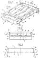
- the heat treatment unit for food products for example for cooking charcuterie products, which is illustrated in FIGS. 1 to 3, bears the reference 1.
- This unit made of stainless steel sheet, thermally good conductor, comprises a bottom plate 3, of generally rectangular shape, the short sides are attached to support elements 2.
- the plate 3 is substantially horizontal.
- the bottom plate 3 consists of a tight flat box, the walls of which upper and lower are referenced 30 and 31.
- the support elements 2 are flanges similar to those of the units described in FR-A-2 672 270 and in the aforementioned prior application 96 03556.
- Each flange 2 is a sheet plate with multiple folding, the part of which lower 23 extends downward, well below the level of the bottom 3, and is shifted towards outside.
- the upper part 22 of the flanges is welded to the bottom plate 3, of which it seals the ends.
- the lower end of the flanges (see Figure 3) is folded inward to form horizontal support faces 21 intended to come to bear on faces horizontal intermediaries 20, which correspond to the outward offset of the middle area of the flanges.
- the unit can be placed on the ground, or any other support - such as rollers, for example-.
- the upper wall of the bottom plate 3 is ribbed.
- the ribs, designated 32, are for example four in number, regularly spaced over the entire width of the bottom; they extend longitudinally, that is to say perpendicular to the end flanges 2.
- the ribbing is obtained by deformation (bending / stamping) of the wall 30, the ribs 32 having a section in the form of an "V" overturned with an apex angle equal 90 °.
- This ribbing improves the rigidity of the wall 30.
- the unit has the shape a watertight container, the bottom plate extending on its long sides by boxes vertical 4a, 4b, which communicate with the interior space of the box forming plate background 3.
- edges of the lower wall 31 are bevelled, having oblique faces 42 through which the junction takes place with the wall external of each of the boxes 4. These faces ensure the mutual centering of two units superimposed when stacked.
- the faces 22 of the support elements 2 also seal the ends of vertical boxes 4.
- a heat transfer fluid for example hot water
- the end pieces 40 and 41 are located at diagonally opposite locations of the unit.
- the box 3 which forms the bottom plate, is internally compartmentalized, so that the heat transfer fluid will flow along a blade, with a trajectory in a baffle illustrated in Figure 6.
- the bottom wall 31 is composed of several elements whose edges have, facing each rib 32, double folding at 45 ° 310, 311.
- connection of the two parts is carried out by a weld line 301 which ensures the separation of the spaces located on each side of this line, inside the caisson.
- Another weld line ensures the connection of one of the two parts folded 311 with the upper wall 30.
- this closure line 301 does not extend over the entire length the bottom plate; on the contrary, it is interrupted at one of its ends, as illustrated in Figure 5, to allow the heat transfer fluid to bypass and give it the trajectory in chicane (or serpentine).
- FC has designated the heat transfer fluid.
- the fluid FC can flow from side to side at one end of the closure line.
- the folded parts 311 define, with the faces of the rib 32, a "dead" space 300, of square section, into which the FC fluid can penetrate, but where it is not normally in movement, this space being blind.
- the stack is placed on a support S , for example on the ground or any other support such as transport rollers.
- Figure 7 have been designated by the reference h the mutual spacing of funds in the stack.
- This spacing h is perfectly defined; it is a function of the height of the parts 23 of the support elements 2.
- the installation includes a pipeline supply of heat transfer liquid, referenced 70, which is connected - preferably by a parallel mounting - on the inlet end pieces 40 of all the units.
- outlet end pieces 41 are connected in parallel to an evacuation pipe 71.
- the bottom plate is shaped and dimensioned to receive side by side four of these products.
- Each product 5 is placed on the upper wall 30 of the bottom plate, longitudinally, between a border box 4 and a rib 32 or between two ribs 32.
- the flattened underside of the product receives calories from the wall top of the bottom plate which supports it. Its flattened upper face receives calories from the bottom wall of the bottom plate of the overlying unit.
- the water temperature will be around 70 ° C, and the time processing time of 6 to 12 hours (depending on the nature and dimensions of the products we are dealing with).
- the unit is preferably dimensioned so that in their ovalized state, the 5 'products are in contact with with each other, and with the inner wall of the side boxes 4a and 4b (also good thermal conductor).
- the installation can also be used to cool cooked products by circulating a cold fluid, for example water Cold.
- a cold fluid for example water Cold.
- the unit is equipped with a overflow device.
- This device simply consists of a tube 8 which passes through a opening of the bottom plate 3, and is fixed therein in a sealed manner, for example by welding.
- This tube stands on a certain height, of predetermined value, a the inside of the unit in the form of a container.
- this height can be adjustable (tube in two parts screwable one inside the other, of variable length).
- Such an installation can in particular be used to receive several molds a individual ham.
- molds 6 of traditional type commonly used in industrial sausages the closing of the lid is provided by racks. This cover is biased by springs, so that put pressure on the ham.
- the support elements 2 have a sufficient height, to prevent the unit base plate does not come into contact with the molds 6 of the underlying unit.
- the water level is chosen so that practically the entire wall height mussels bathe in water, or even that the mussels are completely submerged.
- the cooking here is carried out in a water bath, the heat transfer liquid transferring its heat to the water E which surrounds the molds 6.
- certain molds are placed on ribs 32, which provides a space under the bottom of the mold in which can circulate the bath water, thus promoting heat exchange and homogeneity of cooking.
- the liquid E After cooking, and possibly cooling, the liquid E is discharged.
- each valve is associated with a valve, the assembly being carried by a rod 900 which can slide in a vertical tube 90, and of which the movement is controlled by a jack 91.
- a recovery pump 92 ensures the rejection of the liquid E , or its recycling for a next operation.
- the treatment can be a treatment involving an intake calories - especially for cooking products - or, on the contrary, a treatment with the addition of frigories, in particular for cooling or freezing products.
Landscapes
- Engineering & Computer Science (AREA)
- Food Science & Technology (AREA)
- Life Sciences & Earth Sciences (AREA)
- Wood Science & Technology (AREA)
- Zoology (AREA)
- Meat, Egg Or Seafood Products (AREA)
- General Preparation And Processing Of Foods (AREA)
- Packages (AREA)
- Food Preservation Except Freezing, Refrigeration, And Drying (AREA)
Claims (14)
- Wärmebehandlungseinheit für Nahrungsmittel, die eine horizontale Bodenplatte aufweist, die dafür bestimmt ist, die zu behandelnden Produkte (5, 6) zu tragen, dadurch gekennzeichnet, dass die Bodenplatte (3) aus einem dichten, flachen Behälter besteht, dessen obere Wand (30) zumindest - und vorzugsweise die beiden Wände (30, 31) - wärmeleitend ist (sind), und in dessen Innenraum es möglich ist, ein Wärmeübertragungsfluid (FC) zirkulieren zu lassen, wobei diese Bodenplatte (3) mit Auflageelementen (2) einstückig ausgebildet ist, die ermöglichen, mehrere Einheiten (1) aufeinander aufzustapeln, wobei ihre mit einem bestimmten Zwischenraum voneinander beabstandet angeordneten Bodenplatten (3) vollständig beibehalten werden.
- Einheit gemäß Anspruch 1, dadurch gekennzeichnet, dass die obere Wand (30) mit Rippen versehen ist.
- Einheit gemäß Anspruch 2, dadurch gekennzeichnet, dass die obere Wand mehrere parallele Rippen (32) aufweist, deren Querschnitt die Form eines umgedrehten "V" aufweist.
- Einheit gemäß einem der Ansprüche 1 bis 3, dadurch gekennzeichnet, dass der Innenraum des die Bodenplatte (3) bildenden Behälters derart in Fächer eingeteilt ist, dass das Wärmeübertragungsfluid (FC) einer wellenförmigen Bahn folgt.
- Einheit gemäß den Ansprüchen 3 und 4 in Kombination, dadurch gekennzeichnet, dass der Raum durch Trennlinien (301), die gegenüber den Rippen (32) angeordnet sind, in Fächer unterteilt ist.
- Einheit gemäß einem der Ansprüche 1 bis 5, dadurch gekennzeichnet, dass sie zwei einander gegenüberliegende Seitenflanken aufweist, die eine ebenfalls wärmeleitende Doppelwand aufweisen, und die vertikale, flache Behälter (4a, 4b) bilden, welche mit dem die Bodenplatte (3) bildenden Behälter in Verbindung stehen.
- Einheit gemäß Anspruch 6, dadurch gekennzeichnet, dass die vertikalen Behälter (4a, 4b) mit Anschlussansätzen (40, 41) versehen sind, die ermöglichen, die Einheit (1) jeweils an Zufuhr- und Ablaufleitungen für das Wärmeübertragungsfluid (FC) anzuschließen.
- Einheit gemäß einem der Ansprüche 1 bis 7, dadurch gekennzeichnet, dass die Auflageelemente (2) aus einem Paar vertikaler Flansche bestehen, die an den beiden gegenüberliegenden Kanten der Bodenplatte (3) befestigt sind, und die die Enden des diese letztere bildenden Behälters sowie gegebenenfalls die Enden der vertikalen Behälter (4a, 4b) verschließen.
- Einheit gemäß einem der Ansprüche 1 bis 8, dadurch gekennzeichnet, dass sie aus einem dichten Behälter besteht, der in der Lage ist, eine Flüssigkeit (E) aufzunehmen, in welcher die zu behandelnden Produkte (6) bespült werden können.
- Einheit gemäß Anspruch 9, dadurch gekennzeichnet, dass sie ein Ausleersystem aufweist, wie ein Rohr (8), das die Bodenplatte (3) durchquert und das Ableiten aus dem Überlaufrohr für die Flüssigkeit (E) gewährleistet, wenn diese eine vorbestimmte Höhe (N) erreicht.
- Anlage zur Wärmebehandlung von Nahrungsmitteln und insbesondere Fleischwaren, dadurch gekennzeichnet, dass sie mehrere Einheiten (1) gemäß einem der vorherigen Ansprüche umfasst, welche aufeinander aufgestapelt sind, und dass sie mit Zufuhr- (70) und Ablaufleitungen (71) für das Wärmeübertragungsfluid ausgestattet ist, an welche jede der Einheiten des Stapels angeschlossen ist.
- Anlage gemäß Anspruch 11, dadurch gekennzeichnet, dass sie aus Einheiten gemäß Anspruch 9 oder 10 besteht, und dass sie ein Entleerungssystem mit Ventilklappen (9) aufweist, das in der Lage ist, das Entleeren der Gesamtheit der Behälter sicherzustellen.
- Anlage gemäß Anspruch 11 oder 12, dadurch gekennzeichnet, dass das Wärmeübertragungsfluid (FC) aus einer heißen Flüssigkeit besteht, die ermöglicht, die Nahrungsmittel zu kochen.
- Anlage gemäß Anspruch 11 oder 12, dadurch gekennzeichnet, dass das Wärmeübertragungsfluid (FC) aus einer kalten Flüssigkeit besteht, die ermöglicht, die Nahrungsmittel abzukühlen oder einzufrieren.
Applications Claiming Priority (3)
| Application Number | Priority Date | Filing Date | Title |
|---|---|---|---|
| FR9700647A FR2758438B1 (fr) | 1997-01-17 | 1997-01-17 | Unite de traitement thermique de produits alimentaires |
| FR9700647 | 1997-01-17 | ||
| PCT/FR1998/000056 WO1998031265A1 (fr) | 1997-01-17 | 1998-01-14 | Unite de traitement thermique de produits alimentaires |
Publications (2)
| Publication Number | Publication Date |
|---|---|
| EP0955854A1 EP0955854A1 (de) | 1999-11-17 |
| EP0955854B1 true EP0955854B1 (de) | 2002-10-30 |
Family
ID=9502868
Family Applications (1)
| Application Number | Title | Priority Date | Filing Date |
|---|---|---|---|
| EP98902071A Expired - Lifetime EP0955854B1 (de) | 1997-01-17 | 1998-01-14 | Thermische bearbeitungseinheit für nahrungsmittel |
Country Status (7)
| Country | Link |
|---|---|
| EP (1) | EP0955854B1 (de) |
| CN (1) | CN1135951C (de) |
| AT (1) | ATE226800T1 (de) |
| AU (1) | AU5870998A (de) |
| DE (1) | DE69809028D1 (de) |
| FR (1) | FR2758438B1 (de) |
| WO (1) | WO1998031265A1 (de) |
Families Citing this family (3)
| Publication number | Priority date | Publication date | Assignee | Title |
|---|---|---|---|---|
| FR2965149B1 (fr) | 2010-09-28 | 2014-01-10 | Armor Inox Sa | Moule pour un produit alimentaire |
| JP7061470B2 (ja) * | 2018-01-25 | 2022-04-28 | 四国日清食品株式会社 | 原料肉塊の成型方法 |
| CN110623536B (zh) * | 2018-06-21 | 2021-05-28 | 佛山市顺德区美的电热电器制造有限公司 | 炖蒸器具 |
Family Cites Families (7)
| Publication number | Priority date | Publication date | Assignee | Title |
|---|---|---|---|---|
| DE466168C (de) * | 1928-10-02 | Albert Gutermann | Vorrichtung zum Pressen von Wuerstchen, insbesondere sogenannten Landjaegern | |
| US3796144A (en) * | 1972-05-17 | 1974-03-12 | R Foldenauer | Apparatus for cooking and chilling meat in molds |
| IT8146809A0 (it) * | 1981-02-04 | 1981-02-04 | Langhirano Parma A | Metodo e attrezzatura per laformatura dei prosciutti crudi nei relativi stampi, dopo la disossatura e prima della cucitura |
| AT377680B (de) * | 1982-06-23 | 1985-04-25 | Reisegger August | Rohwurstpresse |
| FR2672270B3 (fr) * | 1991-02-06 | 1993-04-09 | Kaufler Sa | Dispositif de supports associes a des recipients pour des produits alimentaires, particulierement des jambons. |
| US5404935A (en) * | 1991-05-31 | 1995-04-11 | Beltec International | Cabinet-style apparatus for transferring heat to food and cooling food |
| FR2745984B1 (fr) | 1996-03-18 | 1998-05-29 | Unite et installation de moulage et de traitement thermique de produits alimentaires |
-
1997
- 1997-01-17 FR FR9700647A patent/FR2758438B1/fr not_active Expired - Fee Related
-
1998
- 1998-01-14 DE DE69809028T patent/DE69809028D1/de not_active Expired - Lifetime
- 1998-01-14 WO PCT/FR1998/000056 patent/WO1998031265A1/fr not_active Ceased
- 1998-01-14 CN CNB988025515A patent/CN1135951C/zh not_active Expired - Fee Related
- 1998-01-14 AU AU58709/98A patent/AU5870998A/en not_active Abandoned
- 1998-01-14 EP EP98902071A patent/EP0955854B1/de not_active Expired - Lifetime
- 1998-01-14 AT AT98902071T patent/ATE226800T1/de not_active IP Right Cessation
Also Published As
| Publication number | Publication date |
|---|---|
| CN1247456A (zh) | 2000-03-15 |
| CN1135951C (zh) | 2004-01-28 |
| DE69809028D1 (de) | 2002-12-05 |
| WO1998031265A1 (fr) | 1998-07-23 |
| AU5870998A (en) | 1998-08-07 |
| FR2758438B1 (fr) | 1999-04-09 |
| ATE226800T1 (de) | 2002-11-15 |
| EP0955854A1 (de) | 1999-11-17 |
| FR2758438A1 (fr) | 1998-07-24 |
Similar Documents
| Publication | Publication Date | Title |
|---|---|---|
| EP0516568B1 (de) | Wärmeisolierender Konditionierer für den gekühlten oder erwärmten Transport von Behältern mit Nahrungsmitteln | |
| EP0888065B1 (de) | Einheit und vorrichtung zum formen und wärmebehandeln von nahrungsprodukten | |
| EP3785583B1 (de) | Heissluftkochgerät mit mehreren funktionseinstellungen | |
| EP3721760B1 (de) | Heissluftkochgerät mit vorderer öffnung zum einsetzen und entfernen eines kochbehälters | |
| EP0750732A1 (de) | Zweizweckwärmeübertragungselement für isothermische räume, mit einem solchen element versehenener, isothermischer raum | |
| EP0968395B1 (de) | Gekühlter servierwagen | |
| EP0955854A1 (de) | Thermische bearbeitungseinheit für nahrungsmittel | |
| EP0935419B1 (de) | Einheit zur formung und wärmebehandlung von langgestreckten nahrungsprodukten | |
| WO2007009195A1 (fr) | Appareil de cuisson | |
| EP0176462B1 (de) | Verfahren zum Kochen von Nahrungsmitteln, wie Schinken und Vorrichtung zur Durchführung des Verfahrens | |
| EP0656186B1 (de) | Fertiggerichttablett und Temperiervorrichtung zur Aufnahme solcher Tabletts | |
| FR2618983A1 (fr) | Dispositif de combinaison de convoyeurs longitudinaux et transversaux a accumulation pour cuisson, tumage ou refroidissement d'aliments | |
| FR2831248A1 (fr) | Dispositif de remise en temperature d'aliments a double circuit de fluide d'accumulation de chaud et de froid | |
| FR2651645A1 (fr) | Dispositif pour l'amelioration de la qualite de la vendange par maturation ou surmaturation, en vue de la vinification. | |
| EP0072336A1 (de) | Vorrichtung zum Aufwärmen von Nahrungsmitteln auf einzelnen Tabletts | |
| FR3123054A1 (fr) | Contenant comportant un récipient pour denrées et un dispositif de fermeture réutilisables | |
| FR2826715A1 (fr) | Echangeur de chaleur pour recipient souple et dispositif de distribution de liquide alimentaire mettant en oeuvre cet echangeur | |
| FR2899783A1 (fr) | Plat vapeur, notamment pour un four de cuisson a la vapeur | |
| WO2004063086A1 (fr) | Echangeur de chaleur pour recipient souple | |
| FR2480984A1 (fr) | Panier pour stockage compact a sec de barreaux combustibles irradies et leur refroidissement progressif par l'eau | |
| EP4151708A1 (de) | Behälter zur gärung, aufzucht oder lagerung eines alkoholischen lebensmittelpräparats | |
| WO2004075640A2 (fr) | Barquette pour le conditionnement de produits de la mer, en particulier de crevettes ou de langoustines | |
| FR2569533A1 (fr) | Installation de cuisson de produits alimentaires tels que des jambons | |
| FR2693891A1 (fr) | Plateau et vitrine de présentation réfrigérés. | |
| FR2577528A1 (fr) | Emballage thermique pour produits alimentaires |
Legal Events
| Date | Code | Title | Description |
|---|---|---|---|
| PUAI | Public reference made under article 153(3) epc to a published international application that has entered the european phase |
Free format text: ORIGINAL CODE: 0009012 |
|
| 17P | Request for examination filed |
Effective date: 19990728 |
|
| AK | Designated contracting states |
Kind code of ref document: A1 Designated state(s): AT BE CH DE DK ES FI FR GB GR IE IT LI LU MC NL PT SE |
|
| GRAG | Despatch of communication of intention to grant |
Free format text: ORIGINAL CODE: EPIDOS AGRA |
|
| 17Q | First examination report despatched |
Effective date: 20020212 |
|
| GRAG | Despatch of communication of intention to grant |
Free format text: ORIGINAL CODE: EPIDOS AGRA |
|
| GRAH | Despatch of communication of intention to grant a patent |
Free format text: ORIGINAL CODE: EPIDOS IGRA |
|
| GRAH | Despatch of communication of intention to grant a patent |
Free format text: ORIGINAL CODE: EPIDOS IGRA |
|
| GRAA | (expected) grant |
Free format text: ORIGINAL CODE: 0009210 |
|
| AK | Designated contracting states |
Kind code of ref document: B1 Designated state(s): AT BE CH DE DK ES FI FR GB GR IE IT LI LU MC NL PT SE |
|
| PG25 | Lapsed in a contracting state [announced via postgrant information from national office to epo] |
Ref country code: NL Free format text: LAPSE BECAUSE OF FAILURE TO SUBMIT A TRANSLATION OF THE DESCRIPTION OR TO PAY THE FEE WITHIN THE PRESCRIBED TIME-LIMIT Effective date: 20021030 Ref country code: IT Free format text: LAPSE BECAUSE OF FAILURE TO SUBMIT A TRANSLATION OF THE DESCRIPTION OR TO PAY THE FEE WITHIN THE PRESCRIBED TIME-LIMIT;WARNING: LAPSES OF ITALIAN PATENTS WITH EFFECTIVE DATE BEFORE 2007 MAY HAVE OCCURRED AT ANY TIME BEFORE 2007. THE CORRECT EFFECTIVE DATE MAY BE DIFFERENT FROM THE ONE RECORDED. Effective date: 20021030 Ref country code: IE Free format text: LAPSE BECAUSE OF FAILURE TO SUBMIT A TRANSLATION OF THE DESCRIPTION OR TO PAY THE FEE WITHIN THE PRESCRIBED TIME-LIMIT Effective date: 20021030 Ref country code: GR Free format text: LAPSE BECAUSE OF FAILURE TO SUBMIT A TRANSLATION OF THE DESCRIPTION OR TO PAY THE FEE WITHIN THE PRESCRIBED TIME-LIMIT Effective date: 20021030 Ref country code: GB Free format text: LAPSE BECAUSE OF FAILURE TO SUBMIT A TRANSLATION OF THE DESCRIPTION OR TO PAY THE FEE WITHIN THE PRESCRIBED TIME-LIMIT Effective date: 20021030 Ref country code: FI Free format text: LAPSE BECAUSE OF FAILURE TO SUBMIT A TRANSLATION OF THE DESCRIPTION OR TO PAY THE FEE WITHIN THE PRESCRIBED TIME-LIMIT Effective date: 20021030 Ref country code: AT Free format text: LAPSE BECAUSE OF FAILURE TO SUBMIT A TRANSLATION OF THE DESCRIPTION OR TO PAY THE FEE WITHIN THE PRESCRIBED TIME-LIMIT Effective date: 20021030 |
|
| REF | Corresponds to: |
Ref document number: 226800 Country of ref document: AT Date of ref document: 20021115 Kind code of ref document: T |
|
| REG | Reference to a national code |
Ref country code: GB Ref legal event code: FG4D Free format text: NOT ENGLISH |
|
| REG | Reference to a national code |
Ref country code: CH Ref legal event code: EP |
|
| REG | Reference to a national code |
Ref country code: IE Ref legal event code: FG4D Free format text: FRENCH |
|
| REF | Corresponds to: |
Ref document number: 69809028 Country of ref document: DE Date of ref document: 20021205 |
|
| PG25 | Lapsed in a contracting state [announced via postgrant information from national office to epo] |
Ref country code: LU Free format text: LAPSE BECAUSE OF NON-PAYMENT OF DUE FEES Effective date: 20030114 |
|
| PG25 | Lapsed in a contracting state [announced via postgrant information from national office to epo] |
Ref country code: SE Free format text: LAPSE BECAUSE OF FAILURE TO SUBMIT A TRANSLATION OF THE DESCRIPTION OR TO PAY THE FEE WITHIN THE PRESCRIBED TIME-LIMIT Effective date: 20030130 Ref country code: PT Free format text: LAPSE BECAUSE OF FAILURE TO SUBMIT A TRANSLATION OF THE DESCRIPTION OR TO PAY THE FEE WITHIN THE PRESCRIBED TIME-LIMIT Effective date: 20030130 Ref country code: DK Free format text: LAPSE BECAUSE OF FAILURE TO SUBMIT A TRANSLATION OF THE DESCRIPTION OR TO PAY THE FEE WITHIN THE PRESCRIBED TIME-LIMIT Effective date: 20030130 |
|
| PG25 | Lapsed in a contracting state [announced via postgrant information from national office to epo] |
Ref country code: MC Free format text: LAPSE BECAUSE OF NON-PAYMENT OF DUE FEES Effective date: 20030131 Ref country code: LI Free format text: LAPSE BECAUSE OF NON-PAYMENT OF DUE FEES Effective date: 20030131 Ref country code: DE Free format text: LAPSE BECAUSE OF FAILURE TO SUBMIT A TRANSLATION OF THE DESCRIPTION OR TO PAY THE FEE WITHIN THE PRESCRIBED TIME-LIMIT Effective date: 20030131 Ref country code: CH Free format text: LAPSE BECAUSE OF NON-PAYMENT OF DUE FEES Effective date: 20030131 Ref country code: BE Free format text: LAPSE BECAUSE OF NON-PAYMENT OF DUE FEES Effective date: 20030131 |
|
| NLV1 | Nl: lapsed or annulled due to failure to fulfill the requirements of art. 29p and 29m of the patents act | ||
| PG25 | Lapsed in a contracting state [announced via postgrant information from national office to epo] |
Ref country code: ES Free format text: LAPSE BECAUSE OF FAILURE TO SUBMIT A TRANSLATION OF THE DESCRIPTION OR TO PAY THE FEE WITHIN THE PRESCRIBED TIME-LIMIT Effective date: 20030429 |
|
| GBV | Gb: ep patent (uk) treated as always having been void in accordance with gb section 77(7)/1977 [no translation filed] |
Effective date: 20021030 |
|
| REG | Reference to a national code |
Ref country code: IE Ref legal event code: FD4D Ref document number: 0955854E Country of ref document: IE |
|
| PLBE | No opposition filed within time limit |
Free format text: ORIGINAL CODE: 0009261 |
|
| STAA | Information on the status of an ep patent application or granted ep patent |
Free format text: STATUS: NO OPPOSITION FILED WITHIN TIME LIMIT |
|
| REG | Reference to a national code |
Ref country code: CH Ref legal event code: PL |
|
| 26N | No opposition filed |
Effective date: 20030731 |
|
| PGFP | Annual fee paid to national office [announced via postgrant information from national office to epo] |
Ref country code: FR Payment date: 20090112 Year of fee payment: 12 |
|
| REG | Reference to a national code |
Ref country code: FR Ref legal event code: ST Effective date: 20100930 |
|
| PG25 | Lapsed in a contracting state [announced via postgrant information from national office to epo] |
Ref country code: FR Free format text: LAPSE BECAUSE OF NON-PAYMENT OF DUE FEES Effective date: 20100201 |