EP0956940B1 - Gerät zum formen einer reifenverstärkungslage. - Google Patents
Gerät zum formen einer reifenverstärkungslage. Download PDFInfo
- Publication number
- EP0956940B1 EP0956940B1 EP98945592A EP98945592A EP0956940B1 EP 0956940 B1 EP0956940 B1 EP 0956940B1 EP 98945592 A EP98945592 A EP 98945592A EP 98945592 A EP98945592 A EP 98945592A EP 0956940 B1 EP0956940 B1 EP 0956940B1
- Authority
- EP
- European Patent Office
- Prior art keywords
- rigid core
- ribbon piece
- transferring
- ribbon
- peripheral surface
- Prior art date
- Legal status (The legal status is an assumption and is not a legal conclusion. Google has not performed a legal analysis and makes no representation as to the accuracy of the status listed.)
- Expired - Lifetime
Links
- 230000003014 reinforcing effect Effects 0.000 title claims description 23
- 230000002093 peripheral effect Effects 0.000 claims description 60
- 230000007246 mechanism Effects 0.000 claims description 57
- 210000000707 wrist Anatomy 0.000 description 5
- 229910000831 Steel Inorganic materials 0.000 description 4
- 230000015572 biosynthetic process Effects 0.000 description 4
- 239000010959 steel Substances 0.000 description 4
- 238000001514 detection method Methods 0.000 description 3
- 238000007796 conventional method Methods 0.000 description 2
- 210000004247 hand Anatomy 0.000 description 2
- 238000000034 method Methods 0.000 description 2
- 230000036544 posture Effects 0.000 description 2
- 230000008569 process Effects 0.000 description 2
- 238000011144 upstream manufacturing Methods 0.000 description 2
- 238000013459 approach Methods 0.000 description 1
- 230000008859 change Effects 0.000 description 1
- 230000010485 coping Effects 0.000 description 1
- 238000006073 displacement reaction Methods 0.000 description 1
- 230000000694 effects Effects 0.000 description 1
- 239000000835 fiber Substances 0.000 description 1
- 230000004044 response Effects 0.000 description 1
- 239000002436 steel type Substances 0.000 description 1
- 239000004753 textile Substances 0.000 description 1
Images


Classifications
-
- B—PERFORMING OPERATIONS; TRANSPORTING
- B29—WORKING OF PLASTICS; WORKING OF SUBSTANCES IN A PLASTIC STATE IN GENERAL
- B29D—PRODUCING PARTICULAR ARTICLES FROM PLASTICS OR FROM SUBSTANCES IN A PLASTIC STATE
- B29D30/00—Producing pneumatic or solid tyres or parts thereof
- B29D30/06—Pneumatic tyres or parts thereof (e.g. produced by casting, moulding, compression moulding, injection moulding, centrifugal casting)
- B29D30/08—Building tyres
- B29D30/10—Building tyres on round cores, i.e. the shape of the core is approximately identical with the shape of the completed tyre
- B29D30/16—Applying the layers; Guiding or stretching the layers during application
- B29D30/1657—Applying the layers; Guiding or stretching the layers during application by feeding cut-to-length pieces in a direction inclined with respect to the core axis and placing the pieces side-by-side to form an annular element
-
- B—PERFORMING OPERATIONS; TRANSPORTING
- B29—WORKING OF PLASTICS; WORKING OF SUBSTANCES IN A PLASTIC STATE IN GENERAL
- B29C—SHAPING OR JOINING OF PLASTICS; SHAPING OF MATERIAL IN A PLASTIC STATE, NOT OTHERWISE PROVIDED FOR; AFTER-TREATMENT OF THE SHAPED PRODUCTS, e.g. REPAIRING
- B29C2793/00—Shaping techniques involving a cutting or machining operation
- B29C2793/0081—Shaping techniques involving a cutting or machining operation before shaping
-
- B—PERFORMING OPERATIONS; TRANSPORTING
- B29—WORKING OF PLASTICS; WORKING OF SUBSTANCES IN A PLASTIC STATE IN GENERAL
- B29D—PRODUCING PARTICULAR ARTICLES FROM PLASTICS OR FROM SUBSTANCES IN A PLASTIC STATE
- B29D30/00—Producing pneumatic or solid tyres or parts thereof
- B29D30/06—Pneumatic tyres or parts thereof (e.g. produced by casting, moulding, compression moulding, injection moulding, centrifugal casting)
- B29D30/08—Building tyres
- B29D30/10—Building tyres on round cores, i.e. the shape of the core is approximately identical with the shape of the completed tyre
- B29D30/16—Applying the layers; Guiding or stretching the layers during application
- B29D2030/1664—Details, accessories or auxiliary operations not provided for in the other subgroups of B29D30/00
- B29D2030/1685—Details, accessories or auxiliary operations not provided for in the other subgroups of B29D30/00 the layers being applied being already cut to the appropriate length, before the application step
-
- B—PERFORMING OPERATIONS; TRANSPORTING
- B29—WORKING OF PLASTICS; WORKING OF SUBSTANCES IN A PLASTIC STATE IN GENERAL
- B29D—PRODUCING PARTICULAR ARTICLES FROM PLASTICS OR FROM SUBSTANCES IN A PLASTIC STATE
- B29D30/00—Producing pneumatic or solid tyres or parts thereof
- B29D30/06—Pneumatic tyres or parts thereof (e.g. produced by casting, moulding, compression moulding, injection moulding, centrifugal casting)
- B29D30/38—Textile inserts, e.g. cord or canvas layers, for tyres; Treatment of inserts prior to building the tyre
- B29D30/44—Stretching or treating the layers before application on the drum
- B29D2030/4468—Holding the layers
- B29D2030/4493—Holding the layers by using suction means, e.g. vacuum
-
- B—PERFORMING OPERATIONS; TRANSPORTING
- B29—WORKING OF PLASTICS; WORKING OF SUBSTANCES IN A PLASTIC STATE IN GENERAL
- B29D—PRODUCING PARTICULAR ARTICLES FROM PLASTICS OR FROM SUBSTANCES IN A PLASTIC STATE
- B29D30/00—Producing pneumatic or solid tyres or parts thereof
- B29D30/06—Pneumatic tyres or parts thereof (e.g. produced by casting, moulding, compression moulding, injection moulding, centrifugal casting)
- B29D30/70—Annular breakers
- B29D2030/705—Annular breakers the breakers being obtained by cutting a continuous reinforced strip into predefined lengths and placing the cut strips side by side on a suitable support, e.g. a toroidal core or a carcass
-
- Y—GENERAL TAGGING OF NEW TECHNOLOGICAL DEVELOPMENTS; GENERAL TAGGING OF CROSS-SECTIONAL TECHNOLOGIES SPANNING OVER SEVERAL SECTIONS OF THE IPC; TECHNICAL SUBJECTS COVERED BY FORMER USPC CROSS-REFERENCE ART COLLECTIONS [XRACs] AND DIGESTS
- Y10—TECHNICAL SUBJECTS COVERED BY FORMER USPC
- Y10T—TECHNICAL SUBJECTS COVERED BY FORMER US CLASSIFICATION
- Y10T156/00—Adhesive bonding and miscellaneous chemical manufacture
- Y10T156/10—Methods of surface bonding and/or assembly therefor
- Y10T156/1052—Methods of surface bonding and/or assembly therefor with cutting, punching, tearing or severing
- Y10T156/1062—Prior to assembly
- Y10T156/1075—Prior to assembly of plural laminae from single stock and assembling to each other or to additional lamina
-
- Y—GENERAL TAGGING OF NEW TECHNOLOGICAL DEVELOPMENTS; GENERAL TAGGING OF CROSS-SECTIONAL TECHNOLOGIES SPANNING OVER SEVERAL SECTIONS OF THE IPC; TECHNICAL SUBJECTS COVERED BY FORMER USPC CROSS-REFERENCE ART COLLECTIONS [XRACs] AND DIGESTS
- Y10—TECHNICAL SUBJECTS COVERED BY FORMER USPC
- Y10T—TECHNICAL SUBJECTS COVERED BY FORMER US CLASSIFICATION
- Y10T156/00—Adhesive bonding and miscellaneous chemical manufacture
- Y10T156/12—Surface bonding means and/or assembly means with cutting, punching, piercing, severing or tearing
- Y10T156/13—Severing followed by associating with part from same source
Definitions
- the present invention relates to an apparatus for forming a tire reinforcing layer either directly or indirectly on the outer peripheral surface of a rigid core having a circular outer contour.
- a conventional method and apparatus for forming a tire reinforcing layer on the outer peripheral surface of a rigid core with a substantially toroidal shape are disclosed, for example, in JP-A-05-185533.
- a reinforcing element comprising a single cord is supported by a mounting head which is moved to one side, in the width direction, of the crown portion of a core which is slowly rotating, and a leading end of the reinforcing element is then clamped by a clip. Subsequently, the mounting head is moved obliquely along the surface of the crown portion of the core to the other side thereof, so that the reinforcing element is fed from the mounting head and adhered onto the outer peripheral surface of the core as being inclined at a constant angle with respect to the equatorial line of the core. The reinforcing element is then cut by a cutter at a location which is spaced a predetermined distance from its leading end. These steps are repeated so that the reinforcing elements are successively adhered to the outer peripheral surface of the core in parallel with each other to form a belt layer.
- the present invention in one aspect provides apparatus for forming a tire reinforcing layer, comprising: transferring and cutting means for transferring a strip, which comprises a plurality of rubber-coated cords extending in parallel with each other, to a location adjacent to a rigid core having a circular outer contour, and cutting the strip into a predetermined length to form a ribbon piece; transferring and adhering means for transferring the ribbon piece onto an outer peripheral surface of the rigid core and adhering the ribbon piece to said outer peripheral surface as being inclined with reference to an equatorial line of the rigid core by a predetermined angle; and rotating means for rotating the rigid core about a center axis thereof, by an angle which corresponds to the length of the ribbon piece in the circumferential direction; characterized in that said transferring and adhering means comprises magnetic or vacuum attracting elements for attracting and holding at least both end portions of the ribbon piece, and a moving mechanism for moving the magnetic or vacuum attracting elements; and in that said moving mechanism comprises manipulators the number of which is the same as the number of
- the invention in another aspect provides apparatus for forming a tire reinforcing layer, comprising: transferring and cutting means for transferring a strip, which comprises a plurality of rubber-coated cords extending in parallel with each other, to a location adjacent to a rigid core having a circular outer contour, and cutting the strip into a predetermined length to form a ribbon piece; transferring and adhering means for transferring the ribbon piece onto an outer peripheral surface of the rigid core and adhering the ribbon piece to said outer peripheral surface as being inclined with reference to an equatorial line of the rigid core by a predetermined angle; and rotating means for rotating the rigid core about a center axis thereof, by an angle which corresponds to the length of the ribbon piece in the circumferential direction; characterized in that said transferring and adhering means comprises magnetic or vacuum attracting elements for attracting and holding at least both end portions of the ribbon piece, a press mechanism for urging said magnetic or vacuum attracting elements onto the outer peripheral surface of the rigid core with a substantially uniform force, and a moving mechanism for
- a strip is transferred to a location adjacent to a rigid core having a circular outer contour, and is cut into a predetermined length to form a ribbon piece.
- the ribbon piece is transferred onto an outer peripheral surface of the rigid core and adhering the ribbon piece to the outer peripheral surface as being inclined with reference to an equatorial line of the rigid core by a predetermined angle.
- the rigid core is rotated about a center axis thereof, by an angle which corresponds to the length of the ribbon piece in the circumferential direction.
- the ribbon piece has a structure in which a plurality of cords are coated by rubber.
- a plurality of cords can be simultaneously set by one adhering operation of the ribbon piece, thereby reducing the number of adhering operations in forming a tire reinforcing layer and significantly improving the operating efficiency.
- the ribbon piece is cut from the strip at a location which is adjacent to the rigid core, so that the transfer distance required for the ribbon piece when it is to be adhered onto the rigid core can be sufficiently reduced, irrespective of the inclination angle of the cords relative to the equatorial line of the rigid core. From such a point also, it is possible to improve the operational efficiency upon formation of the tire reinforcing layer.
- the transferring and adhering means comprises magnetic or vacuum attracting elements for attracting and holding at least both end portions of the ribbon piece, and a moving mechanism for moving the magnetic or vacuum attracting elements.
- the moving mechanism comprises manipulators the number of which is the same as the number of the magnetic or vacuum attracting elements such that the magnetic or vacuum attracting elements are connected to hands of the respective manipulators.
- the former arrangement is simple in structure and ensures that the ribbon piece is positively held, transferred and adhered, and the latter arrangement is capable of simply and readily coping with changes to the rigid core in terms of the shape and dimension of the outer peripheral surface.
- the transferring and adhering means comprises magnetic or vacuum attracting elements for attracting and holding at least both end portions of the ribbon piece, a press mechanism for urging the magnetic or vacuum attracting elements onto the outer peripheral surface of the rigid core with a substantially uniform force, and a moving mechanism for moving the press mechanism.
- the press mechanism comprises a pair of levers of the same length, having respective one ends which are hinge-connected to each other.
- the other end of each lever is connected to one ends of a pair of lever yokes of the same length.
- the other ends of the yoke levers are connected to a leaf spring which extends linearly in a horizontal plane, such that the pair of levers and the pairs of lever yokes are under predetermined opening.
- the magnetic or vacuum attracting elements are then secured to the leaf spring of the press mechanism.
- pairs of yoke levers are provided in multiple stages, it is readily possible to increase the number of the attracting elements. Also, when the moving mechanism for moving the press mechanism is formed as a manipulator, it is possible to reduce the facility cost, to further simplify the operation and control, and to further increase the operational speed.
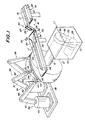
- reference numeral 11 designates a drive portion which includes a rotatable main shaft 12 extending horizontally in the fore-and-aft direction.
- the main shaft 12 has a front end portion where a substantially toroidal rigid core 13 is detachably secured so as to be coaxial with the main shaft 12.
- reference numeral 16 designates a horizontal conveyor device which is inclined, as seen in the plan view of the rigid core 13 with previously formed layers, with reference to the equatorial line E by the same angle as the cords in the belt layer.
- the transfer conveyor device 16 can be operated so that a ribbon-like strip 18 is transferred to a location adjacent to the rigid core 13. It is also possible to arrange the transfer conveyor device in parallel with, or at right angles to the equatorial line E of the rigid core 13.
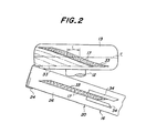
- the ribbon-like strip 18 is comprised of a plurality of steel or textile cords 17, for example two to eight cords, which extend in parallel with each other and are coated by rubber.
- the ribbon-like strip 18 may be immediately after having been molded, or may be the one which has been once wound into a roll-shape after it has been molded.
- the transfer conveyor device 16 is comprised of a first conveyor 19 arranged at a location which is spaced from the rigid core 13, and a second conveyor arranged at a location which is adjacent to the rigid core 13.
- the second conveyor 20 intersects with the main shaft 12 on its upper side.
- the first and second conveyors 19, 20 are comprised of stationary frames 21, 22 extending in the longitudinal direction of the conveyor device 16, pairs of rollers 23, 24 rotatably supported at both end portions of the respective stationary frames 21, 22, belts 25, 26 extending between, and passed over the rollers 23, 24 of the respective pairs, and motors (not shown) for driving one of the rollers 23, 24 of the respective pairs into rotation so that the belts 25, 26 are driven to assume running condition.
- the cutting mechanism 27 is comprised of a stationary cutter blade 28 which extends horizontally at a predetermined inclination angle with respect to the running direction of the first and second conveyors 19, 20, and a movable upper cutter blade 29 which is vertically movably arranged on the upper side of the stationary lower blade 28 and which cooperates with the stationary lower cutter blade 28 during its downward movement.
- Such a cutting mechanism may be replaced by a so-called ring-type device which is comprised of a stationary anvil and a rotary ring cutter which is movable along the stationary anvil, or a knife-type device which is comprised of a stationary anvil and a movable knife which is movable along the stationary anvil.
- Reference numeral 32 designates a detector sensor arranged immediately above the upstream end portion of the second conveyor 20.
- the detector sensor 32 serves to detect the leading end of the ribbon-like strip 18 while it is being transferred, and functions to output a detection signal to a control means, not shown.
- the control means when supplied with the detection signal, causes the first and second conveyors 19, 20 to run over a predetermined distance and stops the running of the conveyors 19, 20 when the leading end of the ribbon-like strip 18 is spaced from the cutting mechanism 27 by a predetermined distance.
- the above-mentioned cutting mechanism 27 is operated in response to the stopping operation of the conveyors 19, 20 and cuts the ribbon-like strip 18 obliquely in its width direction so as to separate a ribbon piece 33 of a predetermined length from the leading end of the ribbon-like strip 18.
- Reference numeral 34 designates a pair of guide members which are arranged at a location corresponding to the upstream end portion of the second conveyor 20. These guide members 34 are arranged to extend in the longitudinal direction of the second conveyor 20, such that they are spaced from each other by an amount which is the same as the width of the ribbon-like strip 18. Thus, when ribbon-like strip 18 transferred by the second conveyor 20 passes a location between the guide members 34, the ribbon-like strip 18 is pushed by the guide members 34 from both sides so as to define the widthwise position on the conveyor.
- the above-mentioned transfer conveyor device 16, the cutting mechanism 27, the detection sensor 32 and the guide members 34 as a whole constitute a transferring and cutting means 35 for transferring the ribbon-like strip 18 to a location adjacent to the rigid core 13, and cutting the ribbon-like strip 18 into a predetermined length to form a ribbon piece 33.
- Reference numeral 38 designates a horizontal base which is arranged on the front side of the rigid core 13.
- a plurality of manipulators e.g., three manipulators are arranged on the base 38 as a moving means which, in the illustrated embodiment, are in the form of vertical, multiple-freedom type industrial robots 39. These robots 39 are arranged along a line which is in parallel with the equatorial line E of the rigid core 13.
- Each robot 39 is comprised of a main body 40 which is rotatable about a vertical axis, a first arm 41 having a proximal end which is connected to the upper end of the main body 40 so that it can be swung in a vertical plane, a second arm 42 having a proximal end which is connected to the distal end of the first arm 41 so that it can be swung in a vertical plane, a first hand 43 connected to the distal end of the second arm 42 so that it can be rotated about the center axis of the second arm 42, and a second hand 44 having a proximal end connected to the distal end of the first hand 43 so that it can be swung in a plane which includes the rotational axis of the first hand 43.
- the second hand 44 has a distal end secured to a magnet body 45 which is rotatable about the center axis of the second hand 44 and is comprised, e.g., of an electromagnet.
- the magnet body 45 holds the ribbon piece 33 by attracting, e.g., the steel-type cords 17 when it is supplied with an electric current, and releases the ribbon piece 33 when the current supply is interrupted.
- the ribbon piece 33 is transferred while being attracted and held by the magnet bodies 45 and the robots 39 at both its end portions and the center portion.
- the ribbon piece 33 may be transferred while being attracted and held only at its end portions by two magnet bodies provided for two robots, respectively, or while being attracted and held by the magnet bodies provided for four or more robots, respectively.
- the robots 39 serve to move the magnet bodies 45 to a desired location along a previously memorized path, while maintaining their initial postures. More specifically, in the illustrated embodiment, the magnet bodies 45 are moved by the robots along the center axis of the main shaft 12 to a position which corresponds to the outer peripheral surface of the rigid core 13. Subsequently, the magnet bodies 45 are caused to undergo relative movements into conformity with the curvature of the outer peripheral surface of the rigid core 13 so as to adhere the ribbon piece 33 onto the outer peripheral surface. During such an adhering process, the ribbon piece 33 assumes a posture relative to the outer peripheral surface of the rigid core 13, in which it is inclined at a predetermined angle with respect to the equatorial line E of the rigid core 13.
- the cord inclination angle at the longitudinal end portions of the ribbon piece 33 with respect to the equatorial line E may be made smaller than the cord inclination angle at the longitudinal center portion, as illustrated, so as to improve the tension bearing property or the so-called hoop effect at the side edge portions of the belt layer which is being formed.
- the magnet bodies 45 may be maintained without being rotated so that the ribbon piece is adhered in its linear state, or both the magnet bodies 45 attracting the end portions of the ribbon piece may be slightly rotated in a clockwise direction so that the ribbon piece is adhered to the outer peripheral surface of the rigid core 13 in a state wherein it is deformed in the opposite direction as compared to the above-mentioned case.
- the above-mentioned robots 39 and the magnet bodies 45 as a whole constitute a transferring and adhering means 46 for transferring the ribbon piece 33 substantially in its width direction, from the transferring and cutting means 35 to the outer peripheral surface of the rigid core 13, and adhering the ribbon piece 33 onto the outer peripheral surface at a predetermined inclination angle with respect to the equatorial line E of the core.
- Reference numeral 50 designates a motor which is accommodated in the above-mentioned drive portion 11.
- a pulley 51 is fixedly connected to the output shaft of the motor 50, and another pulley 52 is fixedly connected to the above-mentioned main shaft 12.
- a timing belt 53 is passed over these pulleys 51 and 52.
- Reference numeral 54 designates an encoder connected to the main shaft 12 for detecting the rotating amount thereof.
- the encoder 54 outputs a signal to the above-mentioned motor 50 to stop the operation thereof.
- the above-mentioned motor 50, the pulleys 51, 52, the timing belt 53 and the encoder 54 as a whole constitute a rotating means which causes the rotation of the rigid core 13 about its center axis by an amount corresponding to the circumferential length L of the ribbon piece 33 on the rigid core 13.
- first and second conveyors 19, 20 of the transferring and cutting means 35 are synchronously driven by operating their respective motors, to thereby transfer the ribbon-like strip 18 in its longitudinal direction toward the rigid core 13.
- the ribbon-like strip 18 passes between the guide members 34 with its side edges defined thereby, so that the widthwise position of the ribbon-like strip 18 on the conveyor is always defined as a predetermined position. Also, the passage of the leading end of the ribbon-like strip 18 during the transfer is detected by the detector sensor 32, and the resulting detecting signal is input to the control means. As a result, both conveyors 19, 20 are driven for a constant duration from the input of the detecting signal, thereby causing the ribbon-like strip 18 to be transferred to a location adjacent to the outer peripheral surface of the rigid core 13.
- the control means outputs a stopping signal to the motors for the conveyors 19, 20 to interrupt their operations.
- the movable upper blade 29 of the cutting mechanism 27 is caused to move downwards so as to cut the ribbon-like strip 18 obliquely in its width direction to form a ribbon piece 33.
- the robots 39 of the transferring and cutting means 46 are operated so that the magnet bodies 45 are moved toward the second conveyor 20 and magnets 45 are urged against both the end portions and the center portion of the ribbon piece 33. Then, the magnet bodies 45 are supplied with an electric current, thereby attracting the steel cords 17 to hold the end portions and the center portion of the ribbon piece 33, respectively.
- the robots 39 are synchronously operated and the magnet bodies 45 attracting and holding the ribbon piece 33 are thereby moved from the location above the second conveyor 20 in the width direction of the ribbon piece 33, i.e. toward an axially front side of the main shaft 12 in the illustrated embodiment, so that the ribbon piece 33 is transferred onto the outer peripheral surface of the rigid core 13. Then, while adjusting the relative positions of the magnet bodies 45 into conformity with the curvature of the outer peripheral surface of the rigid core 13, the ribbon piece 33 is adhered onto the outer peripheral surface of the rigid core 13 with an orientation in which it is inclined to the equatorial line E of the core at a predetermined angle.
- the magnet bodies 45 attracting and holding its end portions may be slightly rotated in a counterclockwise direction.
- the ribbon piece 33 is cut from the ribbon-like strip 18 which has been transferred to a location adjacent to the outer peripheral surface of the rigid core 13, and is transferred to the outer peripheral surface of the core in its width direction. Moreover, the ribbon piece 33 itself includes a plurality of cords extending in parallel with each other. Thus, the transfer distance of the ribbon piece 33 is small even when the ribbon piece is inclined to the equatorial line E of the core by a small angle. It is therefore possible to reduce the number of adhering operations for the ribbon pieces 33 and thereby improve the efficiency of the adhering operations.
- the motor 50 for the rotating means 55 is operated so as to rotate the main shaft 12 and the rigid core 13 about the center axis by a predetermined amount, i.e. an amount which corresponds to the circumferential length L of the ribbon piece 33 which has been adhered onto the outer peripheral surface of the core.
- a predetermined amount i.e. an amount which corresponds to the circumferential length L of the ribbon piece 33 which has been adhered onto the outer peripheral surface of the core.
- the belt piece 33 includes a plurality of cords 17, as explained above, and the adhesion of a single ribbon piece 33 allows a simultaneous setting of a plurality of cords 17, the belt layer can be formed with a reduced number of adhering operations thereby significantly improving the operational efficiency.
- the ribbon piece 33 is transferred to the outer peripheral surface of the rigid core 13 and adhered thereto, and the rigid core 13 is then rotated by a predetermined angle. It is alternatively possible according to the present invention to perform the transfer of the ribbon-like strip and formation of the ribbon piece as external operations simultaneously with the transfer and adhesion of the ribbon piece and the rotation of the rigid core, to further improve the operational efficiency.
- the position of the ribbon-like strip in its width direction is defined by passing the ribbon-like strip 18 through a position between a pair of guide members 34. It is alternatively possible according to the present invention to define the widthwise position of the ribbon-like strip by providing a plurality of guide rollers which are obliquely arranged with an inclination so that the ribbon-like strip is always in contact with the guide rollers on its one side, or by arranging guide magnets on one side of the ribbon-like strip so as to attract the steel cords within the ribbon-like strip.
- the cords forming the ribbon-like body are comprised of organic fiber cords, it is of course that vacuum attracting elements are applied instead of magnetic attracting elements.
- Fig. 3 is a perspective view showing another embodiment of the present invention in which the transferring and adhering means has been modified as compared to the previous embodiment.
- the transferring and adhering means 60 is comprised of a moving mechanism in the form of a manipulator 61 which may be arranged in front of the rigid core 13 connected to the main shaft 12, or on one side thereof as illustrated.
- the manipulator 61 has a final movable stage in the form of a wrist portion 62 which is connected to a single press mechanism 62 to be described hereinafter.
- the press mechanism 63 is provided with a plurality of magnetic or vacuum attracting elements for attracting and holding at least both end portions of the ribbon piece 33, which, for example, are comprised of magnetic attracting elements 64.
- the manipulator 61 is comprised of a post 65 which is rotatable about a vertical axis and which supports an elevation arm 66 extending horizontally therefrom.
- the elevation arm 66 is provided with a transfer mechanism 69 comprised of an advancing arm 67 which is movable horizontally in the axial direction of the axial direction of the elevation arm, and a carrier 68 which is movable horizontally in a direction perpendicular to the horizontal moving direction of the advancing arm 67 and serves to hold the wrist portion 62 so that the wrist portion 62 can be rotated about a vertical axis.
- the press mechanism 63 is comprised of a pair of levers 70 of the same length, having respective one ends which are hinge-connected to each other.
- Each lever 70 has the other end which is connected to one ends of a pair of lever yokes 71 of the same length.
- the other ends of the lever yokes 71 are connected to a leaf spring 72 which extends linearly in a horizontal plane.
- the pair of levers 70 and the pairs of lever yokes 71 are maintained under predetermined openings. It is preferred that the of levers 70 of the pair are biased toward each other and the lever yokes 71 of each pair are biased in directions away from each other, by respective springs.
- the biasing springs assist resilient restoration of the leaf spring 72 to its initial shape.
- the magnetic attracting element 64 can be secured to the press mechanism 63 of such an arrangement, for example, at a location which corresponds to the hinge connection of the lever yoke 71 to the leaf spring 72, where the bottom surface of a cylindrical housing 73 of the magnetic attracting element 64 is threadedly secured to the leaf spring 72 at the periphery of an opening formed in the leaf spring 72, as shown in Fig. 4b.
- the lever yokes 71 of each pair it is preferred for the lever yokes 71 of each pair to have a frame structure which is arranged to bridge over the magnetic attracting element 64, as shown in Fig. 3.
- the magnetic attracting element 64 in the illustrated embodiment may have an arrangement wherein the cylindrical housing 73 is provided therein with a cylinder 74 including a piston rod 75 of which the distal end serves to hold a magnet 76 which may be in the form of a permanent magnet.
- a magnet 76 which may be in the form of a permanent magnet.
- the magnet 76 when the piston rod 75 is in its extended position, the magnet 76 is substantially in alignment with the lower surface of the leaf spring 72 so as to attract and hold the ribbon piece 33 which is mainly composed of steel cords.
- the piston rod 75 is retracted, the magnet 76 is spaced from the ribbon piece 33 to release it.
- the manipulator 61 is operated so that the leaf spring 72 of the press mechanism 63 assuming a flat state is brought into contact and alignment with the ribbon piece 33 which has been transferred by the conveyor 20 to a location adjacent to the rigid core 13.
- the piston rods 75 of the magnetic attracting elements 64 are then advanced so that the ribbon piece 33 is attracted by the magnets 76.
- the ribbon piece 33 is lifted together with the magnetic attracting elements 64 and transferred onto the outer peripheral surface of the rigid core 13.
- the ribbon piece 33 and the leaf spring 72 are then arranged, under the operation of the wrist portion 62 of the manipulator 61, to have a desired inclination angle with respect to the equatorial line of the rigid core which is in a predetermined angular position.
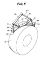
- the elevation arm 66 of the manipulator 61 is moved downwards, thereby causing the ribbon piece 33 to contact the outer peripheral surface of the rigid core and deforming the press mechanism 63 as shown in Fig. 5.
- the leaf spring 72 then functions like an automobile wiper blade, and serves to urge the ribbon piece 33 in conformity with the outer peripheral surface of the rigid core, under a sufficiently uniform force, and adhere the ribbon piece 33 to the outer peripheral surface of the rigid core.
- the deflecting deformation of the leaf spring 72 along the outer peripheral surface of the rigid core is caused by the relative rotation of the lever yoke 71 about its hinge connection to the leaf spring 72. Therefore, it is preferred that the hinge connection is arranged as close as possible, to the lower surface of the leaf spring 72 and, hence, the ribbon piece 33 attracted thereby. Such an arrangement makes it possible to prevent relative displacement, in the longitudinal direction, between the ribbon piece 33 and the leaf spring 72, upon the deflecting deformation of the leaf spring 72 after the ribbon piece 33 has been attracted and held in place.
- the press mechanism may be arranged such that the other end of the lever yoke 71 is hinge-connected to the cylindrical housing 73 of the magnetic attracting element 64 so that the leaf spring 72 is connected indirectly to the lever yoke 71 through the magnetic attracting element 64.
- the press mechanism as a whole, inclusive of the magnetic attracting elements 64, functions like a wiper blade so that leaf spring 72 is smoothly deformed along the outer peripheral surface of the rigid core and the ribbon piece 33 held thereby is urged against the outer peripheral surface of the rigid core with a uniform downward force at any portion in its longitudinal direction.
- Fig. 6 is a schematic view showing the operation of the transferring and adhering means 60 under a different transfer mode of the ribbon piece 33, wherein the ribbon piece 33 is transferred in a direction perpendicular to the center axis of the rigid core 13.
- the ribbon piece 33 is adhered onto the outer peripheral surface of the rigid core under a desired orientation, as follows.
- the magnetic attracting elements 64 are operated so as to attract and hold the ribbon piece 33 which has been transferred by the conveyor to a location adjacent to the rigid core 13.
- the manipulator 61 by operating the manipulator 61, the ribbon piece 33 is translated or moved horizontally to a location above the outer peripheral surface of the rigid core.
- the wrist portion 62 of the manipulator 61 is then operated to rotate the press mechanism 63 so that the ribbon piece attracted and held thereby extends in the desired direction which is inclined with respect to the equatorial line of the rigid core 13.
- the elevation arm 66 is moved downwards and the press mechanism 63 is operated so that the ribbon piece 33 is deformed along the outer peripheral surface of the rigid core.
- the ribbon piece 33 is thus urged against the outer peripheral surface of the rigid core sufficiently uniformly over the entire length, and is thus adhered in the desired manner.
- the rigid core 13 is rotated by a predetermined amount, and the above-mentioned adhering operation is repeated.
- the securing location of the magnetic attracting elements 64 to the press mechanism and the number of the same as desired, within a range wherein the magnetic attracting elements 64 do not cause unnecessary or excessive deflecting deformation of the leaf spring 72.
- five or more magnetic attracting elements 64 may be arranged on the leaf spring at constant intervals so that the ribbon piece 33 can be attracted and held more uniformly, thereby ensuring that the ribbon piece 33 is properly adhered onto the outer peripheral surface of the rigid core at any time, irrespectively of the weight of the ribbon piece.
- the pairs of the lever yokes are arranged in a plurality of stages so that the press mechanism and, hence, the leaf spring have increased length.
- Fig. 7 wherein the lever yokes are provided in two stages.
- the levers 70 of a pair are each hinge-connected to a pair of lever yokes 71, and the other end of each lever yoke 71 is hinge-connected to a pair of lever yokes 77 of the second stage, such that the other end of each lever yoke 77 is connected to the leaf spring 72.
- the length of the press mechanism 63 can be increased by an amount which corresponds to the additional provision of the lever yokes 77 of the second stage, and it is thus possible to increase the number of the magnetic attracting elements 64 in accordance with the increased length.
- the ribbon piece 33 can be urged against the outer peripheral surface of the core with a downward force which is sufficiently uniform over the entire length, thereby ensuring that the ribbon piece is more properly adhered in place.
- the adhering operation is carried out only by the operation and control of a single manipulator 61, thereby making it possible to further increase the operating speed. It will be appreciated from the foregoing description that, according to the present invention, it is possible to highly efficiently form a tire reinforcing layer on the outer peripheral surface of a rigid core.
Landscapes
- Engineering & Computer Science (AREA)
- Mechanical Engineering (AREA)
- Tyre Moulding (AREA)
Claims (5)
- Apparat zum Bilden einer Reifenverstärkungsschicht, aufweisend: Übertragungsund Schneidemittel (35) zum Übertragen eines Streifens (18), der eine Vielzahl von sich parallel zueinander erstreckenden, gummibeschichteten Cordfäden (17) aufweist, nach einer Stelle, die an einen starren Kern (13) angrenzt, der einen kreisförmigen äußeren Umriß hat, und Schneiden des Streifens bei einer vorgegebenen Länge, um ein Bandstück (33) zu bilden; Übertragungs- und Klebemittel (46) zum Übertragen des Bandstücks (33) auf eine äußere Umfangsoberfläche des starren Kerns (13) und Kleben des Bandstücks auf die äußere Umfangsoberfläche, wobei das Bandstück bezüglich der Äquatorlinie (E) des starren Kerns um einen vorgegebenen Winkel geneigt wird; und Drehmittel (50-54) zum Drehen des starren Kerns (13) um seine Mittelachse, um einen Winkel, der der Länge (L) des Bandstücks (33) in der Umfangsrichtung entspricht; dadurch gekennzeichnet, daß die Übertragungs- und Klebemittel (46) aufweisen: magnetische oder Vakuum-Anziehelemente (45), um mindestens die beiden Endbereiche des Bandstücks (33) anzuziehen und festzuhalten, und einen Bewegungsmechanismus, um die magnetischen oder Vakuum-Anziehelemente zu bewegen; und daß der Bewegungsmechanismus Manipulatoren (39) aufweist, deren Anzahl gleich der Anzahl der magnetischen oder Vakuum-Anziehelemente (45) ist, wobei die magnetischen oder Vakuum-Anziehelemente mit Händen (43, 44) der jeweiligen Manipulatoren verbunden sind.
- Apparat zum Bilden einer Reifenverstärkungsschicht, aufweisend: Übertragungsund Schneidemittel (35) zum Übertragen eines Streifens (18), der eine Vielzahl von sich parallel zueinander erstreckenden, gummibeschichteten Cordfäden (17) aufweist, nach einer Stelle, die an einen starren Kern (13) angrenzt, der einen kreisförmigen äußeren Umriß hat, und Schneiden des Streifens bei einer vorgegebenen Länge, um ein Bandstück (33) zu bilden; Übertragungs- und Klebemittel (60) zum Übertragen des Bandstücks (33) auf eine äußere Umfangsoberfläche des starren Kerns (13) und Kleben des Bandstücks auf die äußere Umfangsoberfläche, wobei das Bandstück bezüglich der Äquatorlinie (E) des starren Kerns um einen vorgegebenen Winkel geneigt wird; und Drehmittel (50-54) zum Drehen des starren Kerns (13) um seine Mittelachse, um einen Winkel, der der Länge (L) des Bandstücks (33) in der Umfangsrichtung entspricht; dadurch gekennzeichnet, daß die Übertragungs- und Klebemittel (60) aufweisen: magnetische oder Vakuum-Anziehelemente (64), um mindestens die beiden Endbereiche des Bandstücks (33) anzuziehen und festzuhalten, einen Preßmechanismus (63), um die magnetischen oder Vakuum-Anziehelemente mit einer im wesentlichen gleichmäßigen Kraft auf die äußere Umfangsoberfläche des starren Kerns (13) zu drücken, und einen Bewegungsmechanismus, um den Preßmechanismus zu bewegen; und daß der Preßmechanismus (63) zwei Hebel (70) von gleicher Länge aufweist, wobei die Hebel an ihrem einen Ende gelenkig miteinander verbunden sind, und das andere Ende der Hebel mit einem Ende von zwei Hebeljochen (71) von gleicher Länge verbunden ist, wobei das andere Ende der Hebeljoche mit einer Blattfeder (72) verbunden ist, die sich in einer horizontalen Ebene linear erstreckt, wobei die zwei Hebel (70) und die zwei Hebeljoche (71) eine vorgegebene Öffnung haben, und wobei die magnetischen oder Vakuum-Anziehelemente (64) an der Blattfeder des Preßmechanismus befestigt sind.
- Apparat wie in Anspruch 2 beansprucht, dadurch gekennzeichnet, daß der Bewegungsmechanismus zum Bewegen des Preßmechanismus einen Manipulator (61) aufweist.
- Apparat wie in Anspruch 2 oder 3 beansprucht, dadurch gekennzeichnet, daß die anderen Enden der Hebeljoche (71) mit den magnetischen oder Vakuum-Anziehelementen (64) gelenkig verbunden sind, so daß die Blattfeder (72) über die magnetischen oder Vakuum-Anziehelemente (64) indirekt mit den Hebeljochen (71) verbunden ist.
- Apparat wie in Anspruch 2 oder 3 beansprucht, dadurch gekennzeichnet, daß die Hebel (70) eines Hebelpaars mit zwei Hebeljochen (71) gelenkig verbunden sind, und das andere Ende jedes Hebeljochs (71) mit zwei Hebeljochen (77) einer zweiten Stufe gelenkig verbunden ist, wobei das andere Ende jedes Hebeljochs (77) mit der Blattfeder (72) verbunden ist.
Applications Claiming Priority (3)
| Application Number | Priority Date | Filing Date | Title |
|---|---|---|---|
| JP28777297 | 1997-10-03 | ||
| JP28777297 | 1997-10-03 | ||
| PCT/JP1998/004464 WO1999017920A1 (fr) | 1997-10-03 | 1998-10-02 | Procede et appareil pour former une couche de renfort d'un pneu |
Publications (3)
| Publication Number | Publication Date |
|---|---|
| EP0956940A1 EP0956940A1 (de) | 1999-11-17 |
| EP0956940A4 EP0956940A4 (de) | 2000-12-06 |
| EP0956940B1 true EP0956940B1 (de) | 2003-04-02 |
Family
ID=17721558
Family Applications (1)
| Application Number | Title | Priority Date | Filing Date |
|---|---|---|---|
| EP98945592A Expired - Lifetime EP0956940B1 (de) | 1997-10-03 | 1998-10-02 | Gerät zum formen einer reifenverstärkungslage. |
Country Status (6)
| Country | Link |
|---|---|
| US (1) | US6355126B1 (de) |
| EP (1) | EP0956940B1 (de) |
| JP (1) | JP4315476B2 (de) |
| DE (1) | DE69812900T2 (de) |
| ES (1) | ES2195390T3 (de) |
| WO (1) | WO1999017920A1 (de) |
Cited By (2)
| Publication number | Priority date | Publication date | Assignee | Title |
|---|---|---|---|---|
| KR20170121201A (ko) * | 2015-02-06 | 2017-11-01 | 더 스틸래스틱 캄파니 엘.엘.씨. | 벨트 성형 시스템 및 타이어 벨트의 적어도 일부를 제조하기 위한 방법 |
| US12179449B2 (en) | 2019-09-04 | 2024-12-31 | The Steelastic Company, Llc | Transfer tooling for varying tire belt sizes |
Families Citing this family (60)
| Publication number | Priority date | Publication date | Assignee | Title |
|---|---|---|---|---|
| JP4358350B2 (ja) * | 1999-04-19 | 2009-11-04 | 株式会社ブリヂストン | タイヤ補強層の形成方法および装置 |
| JP2001088225A (ja) * | 1999-09-21 | 2001-04-03 | Bridgestone Corp | タイヤ構成ベルト製造方法及び製造装置 |
| ATE267082T1 (de) * | 1999-11-26 | 2004-06-15 | Pirelli | Verfahren und vorrichtung zur herstellung einer verstärkungsstruktur für fahrzeugluftreifen |
| WO2002055289A1 (en) * | 2001-01-12 | 2002-07-18 | Bridgestone Corporation | Tire construction member producing method and device therefor |
| JP4787430B2 (ja) * | 2001-07-23 | 2011-10-05 | 株式会社ブリヂストン | タイヤ用コード補強層の形成方法 |
| EP1448401A1 (de) * | 2001-11-27 | 2004-08-25 | PIRELLI PNEUMATICI S.p.A. | Verfahren zur herstellung einer gürtelkonstruktion für reifen von fahrzeugrädern und solch einen gürtel enthaltender radialreifen |
| JP2003191713A (ja) * | 2001-12-28 | 2003-07-09 | Bridgestone Corp | 空気入りラジアルタイヤ |
| DE10201368C1 (de) * | 2002-01-16 | 2003-05-28 | Fischer Maschf Karl E | Schere zum Schneiden von Bandmaterial |
| JP2003251711A (ja) * | 2002-03-01 | 2003-09-09 | Toyo Tire & Rubber Co Ltd | タイヤのベルト成形装置およびベルト成形方法 |
| JP4637575B2 (ja) * | 2002-06-03 | 2011-02-23 | ソシエテ ド テクノロジー ミシュラン | 容積制御でタイヤ補強構造物を製造する方法 |
| DE60312986T2 (de) * | 2002-06-03 | 2007-12-13 | Société de Technologie Michelin | Vorrichtung zur herstellung einer verstärkungsstruktur für einen reifen mit einem wulstfahnendrehmechanismus |
| JP4075981B2 (ja) * | 2002-06-03 | 2008-04-16 | 横浜ゴム株式会社 | 帯状ゴム部材の製造方法 |
| JP2004017498A (ja) * | 2002-06-17 | 2004-01-22 | Sumitomo Rubber Ind Ltd | ストリップ片接合体製造方法、及びそれに用いるストリップ片接合体製造装置 |
| KR100461692B1 (ko) * | 2002-07-22 | 2004-12-14 | 한국타이어 주식회사 | 타이어 보강재 부착장치 |
| US20040154727A1 (en) * | 2003-02-11 | 2004-08-12 | Weissert James Thomas | Method and apparatus for manufacturing carcass plies for a tire |
| EP1447210B1 (de) * | 2003-02-13 | 2007-03-07 | Société de Technologie Michelin | Formgebung und Anlegen einer Reifengürtellage auf eine Haltevorrichtung |
| JP4365678B2 (ja) * | 2003-12-24 | 2009-11-18 | 住友ゴム工業株式会社 | タイヤ用のコードプライ及びタイヤの製造方法 |
| US20050183815A1 (en) * | 2004-02-25 | 2005-08-25 | Toshiyuki Tanaka | Tire ply forming apparatus and process |
| US7344614B2 (en) * | 2004-11-01 | 2008-03-18 | The Goodyear Tire & Rubber Company | Tire breaker strip application method and tire fabricated therefrom |
| WO2006106562A1 (ja) * | 2005-03-29 | 2006-10-12 | Toyo Tire & Rubber Co., Ltd. | タイヤ用ベルトの製造方法及び装置 |
| DE112005003631B4 (de) * | 2005-07-15 | 2020-09-24 | Toyo Tire & Rubber Co., Ltd. | Herstellverfahren für ein Gürtelelement |
| JP4753649B2 (ja) * | 2005-07-26 | 2011-08-24 | 株式会社ブリヂストン | タイヤ構成部材の製造方法および製造装置。 |
| US7497241B2 (en) * | 2005-07-27 | 2009-03-03 | The Steelastic Company, Llc | Tire belt machine |
| US8454777B2 (en) * | 2006-01-30 | 2013-06-04 | Toyo Tire & Rubber Co., Ltd. | Method and apparatus of adhering and building belt member |
| DE602006016346D1 (de) * | 2006-05-30 | 2010-09-30 | Pirelli | Verfahren und vorrichtung zur herstellung von reifen für fahrzeugräder |
| WO2008001152A1 (en) * | 2006-06-29 | 2008-01-03 | Pirelli Tyre S.P.A. | Process for manufacturing tyres for vehicle wheels |
| WO2008015486A1 (en) | 2006-07-28 | 2008-02-07 | Pirelli Tyre S.P.A. | Process and apparatus for manufacturing a reinforcing structure for tyres of vehicles |
| US9314982B2 (en) | 2006-07-28 | 2016-04-19 | Pirelli Tyre S.P.A. | Process and apparatus for manufacturing a reinforcing structure for tyres of vehicles |
| JP5022677B2 (ja) * | 2006-11-21 | 2012-09-12 | 株式会社ブリヂストン | タイヤ構成部材の製造装置 |
| US7767052B2 (en) * | 2006-12-18 | 2010-08-03 | The Goodyear Tire & Rubber Company | Method of assembling an electronic device into a tire |
| US7914058B2 (en) * | 2006-12-18 | 2011-03-29 | The Goodyear Tire & Rubber Company | Picking apparatus for an electronic device |
| CN101765496B (zh) * | 2007-06-29 | 2013-06-26 | 倍耐力轮胎股份公司 | 用于制造车轮轮胎的方法和装置 |
| EP2200814B1 (de) * | 2007-09-10 | 2014-01-08 | Pirelli Tyre S.P.A. | Verfahren und vorrichtung zur herstellung einer verstärkungsstruktur für fahrzeugreifen |
| US20100193109A1 (en) * | 2007-09-10 | 2010-08-05 | Pirelli Tyre S.P.A. | Process for manufacturing a reinforcing structure for vehicle tyres |
| BRPI0722279B1 (pt) | 2007-11-30 | 2018-09-25 | Pirelli | método de construção de pelo menos uma lona de carcaça, processo para fabricação de pneus, e, aparelho para fabricação de pneus |
| CN102245374B (zh) * | 2008-12-11 | 2014-07-16 | 倍耐力轮胎股份公司 | 用于制造车轮轮胎的方法和设备 |
| US9527256B2 (en) | 2009-10-13 | 2016-12-27 | Pirelli Tyre S.P.A. | Process and apparatus for building tyres for vehicle wheels |
| EP2512790B1 (de) * | 2009-12-14 | 2014-06-04 | Pirelli Tyre S.p.A. | Verfahren für die herstellung von reifen für fahrzeugräder |
| JP6005049B2 (ja) * | 2010-11-18 | 2016-10-12 | ピレリ・タイヤ・ソチエタ・ペル・アツィオーニ | 車両用車輪のタイヤを成形するための方法および装置 |
| IT1403131B1 (it) * | 2010-12-14 | 2013-10-04 | Pirelli | Processo ed apparato per realizzare una struttura di rinforzo di un pneumatico per ruote di veicoli. |
| JP5462817B2 (ja) * | 2011-02-21 | 2014-04-02 | 住友ゴム工業株式会社 | 空気入りタイヤの製造方法 |
| WO2012153175A1 (en) * | 2011-05-12 | 2012-11-15 | Pirelli Tyre S.P.A. | Process and plant for building tyres for vehicle wheels |
| JP5281677B2 (ja) * | 2011-06-15 | 2013-09-04 | 住友ゴム工業株式会社 | タイヤ用プライ材料の製造装置 |
| JP5432970B2 (ja) * | 2011-11-21 | 2014-03-05 | 住友ゴム工業株式会社 | タイヤ用プライ材料の製造装置 |
| ITMI20112349A1 (it) | 2011-12-22 | 2013-06-23 | Pirelli | Processo ed apparato per la produzione di pneumatici per ruote di veicoli |
| JP6063691B2 (ja) * | 2012-10-02 | 2017-01-18 | 住友ゴム工業株式会社 | ゴムストリップ巻回体形成装置 |
| FR2999470B1 (fr) * | 2012-12-13 | 2015-01-09 | Michelin & Cie | Procede et dispositif de fabrication d'ebauche de pneumatique |
| CN104936769B (zh) * | 2012-12-21 | 2017-11-24 | 肖特兄弟公司 | 织物搬运设备 |
| NL2011764C2 (en) * | 2013-11-08 | 2015-05-11 | Vmi Holland Bv | Method for centering a tire component. |
| WO2016204746A1 (en) * | 2015-06-17 | 2016-12-22 | Compagnie Generale Des Etablissements Michelin | A transporter for posing a tire ply on a drum and a method of using the same |
| BR112019007764B1 (pt) * | 2016-11-22 | 2022-10-25 | Pirelli Tyre S.P.A | Processo e aparelho para aplicar elementos redutores de ruído a um pneu para rodas de veículo |
| NL2018057B1 (en) | 2016-12-23 | 2018-07-02 | Vmi Holland Bv | Cutting device and method for cutting-off a length of a continuous strip to form a tire component |
| JP6648771B2 (ja) * | 2018-02-16 | 2020-02-14 | 横浜ゴム株式会社 | タイヤの製造方法 |
| FR3084279B1 (fr) * | 2018-05-17 | 2020-07-10 | Compagnie Generale Des Etablissements Michelin | Installation de fabrication de nappes de renfort avec dispositif de retournement a plat de bandelettes |
| JP7572628B2 (ja) * | 2021-03-04 | 2024-10-24 | 横浜ゴム株式会社 | タイヤの製造方法および成形装置 |
| NL2028821B1 (en) * | 2021-07-23 | 2023-01-30 | Vmi Holland Bv | Dual tire component servicer and method for supplying dual tire components to a tire building drum |
| HUE072956T2 (hu) | 2021-07-23 | 2025-12-28 | Vmi Holland Bv | Kettõs gumiabroncselem-ellátó berendezés és eljárás kettõ gumiabroncselem abroncsépítõ dobhoz történõ adagolására |
| JP2023038118A (ja) * | 2021-09-06 | 2023-03-16 | 株式会社ブリヂストン | タイヤ及びタイヤの製造方法 |
| FR3128897B1 (fr) * | 2021-11-09 | 2023-09-29 | Michelin & Cie | Installation de fabrication de bandages pneumatiques pourvue de compas suiveurs d’outils |
| JP7713863B2 (ja) * | 2021-11-11 | 2025-07-28 | 株式会社ブリヂストン | 生タイヤ成型方法、及び、生タイヤ成型装置 |
Family Cites Families (14)
| Publication number | Priority date | Publication date | Assignee | Title |
|---|---|---|---|---|
| US1453865A (en) * | 1919-05-08 | 1923-05-01 | Dickinson | Method of constructing pneumatic tires |
| US1728957A (en) * | 1923-03-16 | 1929-09-24 | Dickinson Cord Tire Corp | Cord-tire-making machine |
| US2902082A (en) * | 1957-06-26 | 1959-09-01 | Goodrich Co B F | Tire tread transfer apparatus |
| US3431962A (en) * | 1966-08-22 | 1969-03-11 | Goodyear Tire & Rubber | Reinforcement for pneumatic tires and the like |
| US3826297A (en) * | 1972-10-26 | 1974-07-30 | Steelastic Co | Radial tire carcass |
| GB1487426A (en) * | 1974-09-17 | 1977-09-28 | Bekaert Sa Nv | Reinforcement of vehicle tyres |
| JPS51139878A (en) * | 1975-05-29 | 1976-12-02 | Mitsubishi Heavy Ind Ltd | Tire material winding device in tire molder |
| US4861406A (en) * | 1987-08-17 | 1989-08-29 | The Boeing Company | Method and apparatus for handling plies of composite material |
| DE4005401A1 (de) * | 1990-02-21 | 1991-08-22 | Continental Ag | Greif- und transportvorrichtung fuer einer reifenaufbautrommel zuzufuehrende bandagen |
| FR2677578A1 (fr) * | 1991-06-17 | 1992-12-18 | Sedepro | Procede de fabrication d'un pneumatique et machines pour la mise en óoeuvre de ce procede. |
| JPH05124130A (ja) * | 1991-10-30 | 1993-05-21 | Bridgestone Corp | 帯状部材の供給装置および供給方法 |
| JPH08258507A (ja) * | 1995-03-24 | 1996-10-08 | Bridgestone Corp | 空気入りラジアルタイヤ |
| US5743975A (en) * | 1995-03-24 | 1998-04-28 | The Goodyear Tire & Rubber Company | Radial medium truck tire with organic polymer reinforced top belt or breaker |
| PT928680E (pt) | 1997-12-30 | 2003-07-31 | Pirelli | Metodo para fabricar pneus para rodas de veiculo |
-
1998
- 1998-10-02 DE DE69812900T patent/DE69812900T2/de not_active Expired - Lifetime
- 1998-10-02 WO PCT/JP1998/004464 patent/WO1999017920A1/ja not_active Ceased
- 1998-10-02 EP EP98945592A patent/EP0956940B1/de not_active Expired - Lifetime
- 1998-10-02 ES ES98945592T patent/ES2195390T3/es not_active Expired - Lifetime
- 1998-10-02 JP JP51537299A patent/JP4315476B2/ja not_active Expired - Fee Related
- 1998-10-02 US US09/308,996 patent/US6355126B1/en not_active Expired - Lifetime
Cited By (2)
| Publication number | Priority date | Publication date | Assignee | Title |
|---|---|---|---|---|
| KR20170121201A (ko) * | 2015-02-06 | 2017-11-01 | 더 스틸래스틱 캄파니 엘.엘.씨. | 벨트 성형 시스템 및 타이어 벨트의 적어도 일부를 제조하기 위한 방법 |
| US12179449B2 (en) | 2019-09-04 | 2024-12-31 | The Steelastic Company, Llc | Transfer tooling for varying tire belt sizes |
Also Published As
| Publication number | Publication date |
|---|---|
| WO1999017920A1 (fr) | 1999-04-15 |
| EP0956940A4 (de) | 2000-12-06 |
| ES2195390T3 (es) | 2003-12-01 |
| EP0956940A1 (de) | 1999-11-17 |
| JP4315476B2 (ja) | 2009-08-19 |
| DE69812900T2 (de) | 2004-02-26 |
| DE69812900D1 (de) | 2003-05-08 |
| US6355126B1 (en) | 2002-03-12 |
Similar Documents
| Publication | Publication Date | Title |
|---|---|---|
| EP0956940B1 (de) | Gerät zum formen einer reifenverstärkungslage. | |
| JPWO1999017920A1 (ja) | タイヤ補強層の形成方法および装置 | |
| EP3359939B1 (de) | Vorrichtung und verfahren zum automatischen aufbringen von gewichtsmaterial auf ein rad | |
| US8863628B2 (en) | Apparatus for trimming paper rolls or logs and an operating method for treating the logs | |
| US3904471A (en) | Tire building apparatus | |
| US4411724A (en) | Process of and apparatus for splicing cord ply segments at their end faces | |
| CA1304661C (en) | Second stage tire building machine and method | |
| US4961813A (en) | Servicer for tire building machine | |
| EP2272656A1 (de) | Verfahren und vorrichtung zur herstellung eines reifenrohlings | |
| JP2544117B2 (ja) | 細幅帯状体の供給装置 | |
| CA2529780A1 (en) | Robot | |
| US11312035B2 (en) | Cutting device and cutting method of cord-embedded rubber sheet member | |
| EP0253067B1 (de) | Automatische Querverspleissvorrichtung bei Reifenaufbau | |
| JP4357027B2 (ja) | シート状部材の製造方法および装置 | |
| CN2598744Y (zh) | 一种纤维帘布裁断拼接机 | |
| US4976807A (en) | Apparatus for sticking a metal cord strip | |
| JP4377158B2 (ja) | タイヤコード貼付装置 | |
| JPH0769539A (ja) | 線材巻付け装置 | |
| JPH10296873A (ja) | 空気入りタイヤのベルト層成形方法及び装置 | |
| JP4313095B2 (ja) | タイヤ用コード入りシート部材の製造方法及び装置 | |
| US5779850A (en) | Apparatus for joining together the opposite ends of a belt-shaped member | |
| CN220031228U (zh) | 用于拼接轮胎部件以形成连续条带的拼接器 | |
| EP3573819A1 (de) | Vorrichtung und verfahren zum aufbringen eines gummierten bandes auf einer kante einer kordverstärkten schicht | |
| JPH04350061A (ja) | フィルム自動巻取装置 | |
| KR20020042292A (ko) | 비드공급장치 |
Legal Events
| Date | Code | Title | Description |
|---|---|---|---|
| PUAI | Public reference made under article 153(3) epc to a published international application that has entered the european phase |
Free format text: ORIGINAL CODE: 0009012 |
|
| 17P | Request for examination filed |
Effective date: 19990611 |
|
| AK | Designated contracting states |
Kind code of ref document: A1 Designated state(s): DE ES FR IT |
|
| A4 | Supplementary search report drawn up and despatched |
Effective date: 20001020 |
|
| AK | Designated contracting states |
Kind code of ref document: A4 Designated state(s): DE ES FR IT |
|
| 17Q | First examination report despatched |
Effective date: 20010907 |
|
| GRAG | Despatch of communication of intention to grant |
Free format text: ORIGINAL CODE: EPIDOS AGRA |
|
| RTI1 | Title (correction) |
Free format text: APPARATUS FOR FORMING A TIRE REINFORCING LAYER. |
|
| GRAG | Despatch of communication of intention to grant |
Free format text: ORIGINAL CODE: EPIDOS AGRA |
|
| GRAH | Despatch of communication of intention to grant a patent |
Free format text: ORIGINAL CODE: EPIDOS IGRA |
|
| GRAH | Despatch of communication of intention to grant a patent |
Free format text: ORIGINAL CODE: EPIDOS IGRA |
|
| GRAA | (expected) grant |
Free format text: ORIGINAL CODE: 0009210 |
|
| AK | Designated contracting states |
Designated state(s): DE ES FR IT |
|
| REF | Corresponds to: |
Ref document number: 69812900 Country of ref document: DE Date of ref document: 20030508 Kind code of ref document: P |
|
| ET | Fr: translation filed | ||
| PLBE | No opposition filed within time limit |
Free format text: ORIGINAL CODE: 0009261 |
|
| STAA | Information on the status of an ep patent application or granted ep patent |
Free format text: STATUS: NO OPPOSITION FILED WITHIN TIME LIMIT |
|
| 26N | No opposition filed |
Effective date: 20040105 |
|
| PGFP | Annual fee paid to national office [announced via postgrant information from national office to epo] |
Ref country code: ES Payment date: 20091023 Year of fee payment: 12 Ref country code: DE Payment date: 20090923 Year of fee payment: 12 |
|
| PGFP | Annual fee paid to national office [announced via postgrant information from national office to epo] |
Ref country code: IT Payment date: 20091014 Year of fee payment: 12 Ref country code: FR Payment date: 20091029 Year of fee payment: 12 |
|
| PG25 | Lapsed in a contracting state [announced via postgrant information from national office to epo] |
Ref country code: FR Free format text: LAPSE BECAUSE OF NON-PAYMENT OF DUE FEES Effective date: 20101102 |
|
| REG | Reference to a national code |
Ref country code: FR Ref legal event code: ST Effective date: 20110630 |
|
| REG | Reference to a national code |
Ref country code: DE Ref legal event code: R119 Ref document number: 69812900 Country of ref document: DE Effective date: 20110502 |
|
| REG | Reference to a national code |
Ref country code: ES Ref legal event code: FD2A Effective date: 20111118 |
|
| PG25 | Lapsed in a contracting state [announced via postgrant information from national office to epo] |
Ref country code: IT Free format text: LAPSE BECAUSE OF NON-PAYMENT OF DUE FEES Effective date: 20101002 |
|
| PG25 | Lapsed in a contracting state [announced via postgrant information from national office to epo] |
Ref country code: ES Free format text: LAPSE BECAUSE OF NON-PAYMENT OF DUE FEES Effective date: 20101003 |
|
| PG25 | Lapsed in a contracting state [announced via postgrant information from national office to epo] |
Ref country code: DE Free format text: LAPSE BECAUSE OF NON-PAYMENT OF DUE FEES Effective date: 20110502 |