EP0957314A2 - Dispositif de commande pour des brûleurs à gaz - Google Patents
Dispositif de commande pour des brûleurs à gaz Download PDFInfo
- Publication number
- EP0957314A2 EP0957314A2 EP99109002A EP99109002A EP0957314A2 EP 0957314 A2 EP0957314 A2 EP 0957314A2 EP 99109002 A EP99109002 A EP 99109002A EP 99109002 A EP99109002 A EP 99109002A EP 0957314 A2 EP0957314 A2 EP 0957314A2
- Authority
- EP
- European Patent Office
- Prior art keywords
- gas
- pressure
- pressure regulator
- control device
- valve
- Prior art date
- Legal status (The legal status is an assumption and is not a legal conclusion. Google has not performed a legal analysis and makes no representation as to the accuracy of the status listed.)
- Granted
Links
Images


Classifications
-
- F—MECHANICAL ENGINEERING; LIGHTING; HEATING; WEAPONS; BLASTING
- F23—COMBUSTION APPARATUS; COMBUSTION PROCESSES
- F23D—BURNERS
- F23D14/00—Burners for combustion of a gas, e.g. of a gas stored under pressure as a liquid
- F23D14/46—Details
- F23D14/60—Devices for simultaneous control of gas and combustion air
-
- F—MECHANICAL ENGINEERING; LIGHTING; HEATING; WEAPONS; BLASTING
- F23—COMBUSTION APPARATUS; COMBUSTION PROCESSES
- F23N—REGULATING OR CONTROLLING COMBUSTION
- F23N1/00—Regulating fuel supply
- F23N1/02—Regulating fuel supply conjointly with air supply
- F23N1/022—Regulating fuel supply conjointly with air supply using electronic means
-
- F—MECHANICAL ENGINEERING; LIGHTING; HEATING; WEAPONS; BLASTING
- F23—COMBUSTION APPARATUS; COMBUSTION PROCESSES
- F23N—REGULATING OR CONTROLLING COMBUSTION
- F23N5/00—Systems for controlling combustion
- F23N5/18—Systems for controlling combustion using detectors sensitive to rate of flow of air or fuel
- F23N5/184—Systems for controlling combustion using detectors sensitive to rate of flow of air or fuel using electronic means
-
- F—MECHANICAL ENGINEERING; LIGHTING; HEATING; WEAPONS; BLASTING
- F23—COMBUSTION APPARATUS; COMBUSTION PROCESSES
- F23D—BURNERS
- F23D2208/00—Control devices associated with burners
-
- F—MECHANICAL ENGINEERING; LIGHTING; HEATING; WEAPONS; BLASTING
- F23—COMBUSTION APPARATUS; COMBUSTION PROCESSES
- F23N—REGULATING OR CONTROLLING COMBUSTION
- F23N5/00—Systems for controlling combustion
- F23N5/18—Systems for controlling combustion using detectors sensitive to rate of flow of air or fuel
- F23N2005/181—Systems for controlling combustion using detectors sensitive to rate of flow of air or fuel using detectors sensitive to rate of flow of air
-
- F—MECHANICAL ENGINEERING; LIGHTING; HEATING; WEAPONS; BLASTING
- F23—COMBUSTION APPARATUS; COMBUSTION PROCESSES
- F23N—REGULATING OR CONTROLLING COMBUSTION
- F23N2225/00—Measuring
- F23N2225/04—Measuring pressure
-
- F—MECHANICAL ENGINEERING; LIGHTING; HEATING; WEAPONS; BLASTING
- F23—COMBUSTION APPARATUS; COMBUSTION PROCESSES
- F23N—REGULATING OR CONTROLLING COMBUSTION
- F23N2225/00—Measuring
- F23N2225/08—Measuring temperature
- F23N2225/10—Measuring temperature stack temperature
-
- F—MECHANICAL ENGINEERING; LIGHTING; HEATING; WEAPONS; BLASTING
- F23—COMBUSTION APPARATUS; COMBUSTION PROCESSES
- F23N—REGULATING OR CONTROLLING COMBUSTION
- F23N2225/00—Measuring
- F23N2225/08—Measuring temperature
- F23N2225/19—Measuring temperature outlet temperature water heat-exchanger
-
- F—MECHANICAL ENGINEERING; LIGHTING; HEATING; WEAPONS; BLASTING
- F23—COMBUSTION APPARATUS; COMBUSTION PROCESSES
- F23N—REGULATING OR CONTROLLING COMBUSTION
- F23N2233/00—Ventilators
- F23N2233/06—Ventilators at the air intake
- F23N2233/08—Ventilators at the air intake with variable speed
-
- F—MECHANICAL ENGINEERING; LIGHTING; HEATING; WEAPONS; BLASTING
- F23—COMBUSTION APPARATUS; COMBUSTION PROCESSES
- F23N—REGULATING OR CONTROLLING COMBUSTION
- F23N2235/00—Valves, nozzles or pumps
- F23N2235/12—Fuel valves
- F23N2235/14—Fuel valves electromagnetically operated
-
- F—MECHANICAL ENGINEERING; LIGHTING; HEATING; WEAPONS; BLASTING
- F23—COMBUSTION APPARATUS; COMBUSTION PROCESSES
- F23N—REGULATING OR CONTROLLING COMBUSTION
- F23N2235/00—Valves, nozzles or pumps
- F23N2235/12—Fuel valves
- F23N2235/16—Fuel valves variable flow or proportional valves
-
- F—MECHANICAL ENGINEERING; LIGHTING; HEATING; WEAPONS; BLASTING
- F23—COMBUSTION APPARATUS; COMBUSTION PROCESSES
- F23N—REGULATING OR CONTROLLING COMBUSTION
- F23N2235/00—Valves, nozzles or pumps
- F23N2235/12—Fuel valves
- F23N2235/18—Groups of two or more valves
-
- F—MECHANICAL ENGINEERING; LIGHTING; HEATING; WEAPONS; BLASTING
- F23—COMBUSTION APPARATUS; COMBUSTION PROCESSES
- F23N—REGULATING OR CONTROLLING COMBUSTION
- F23N2235/00—Valves, nozzles or pumps
- F23N2235/12—Fuel valves
- F23N2235/20—Membrane valves
Definitions
- the invention relates to a control device for gas burners according to the preamble of Claim 1.
- Control devices for gas burners are from the prior art, for. B. the EP 0 390 964 A1, well known.
- Adaptive servo pressure regulator for various Gas types are known from DE 42 30 201 A1 and from EP 0 103 303 A2.
- a control device To inside the gas burner for optimal and complete combustion of the To provide fuel, namely the gas, a control device must have the gas burner supply an appropriately coordinated gas / air mixture.
- the quality of the gas provided by the gas supply - the quality of gas is determined by a so-called Wobbe index defined - fluctuates, the control device must do so react and to ensure the optimal and complete combustion that Gas / air mixture vary depending on the quality of the gas.
- the present invention is based on the problem, one To create control device for gas burners with the simplest possible constructive Even with fluctuating gas quality, an optimal gas / air mixture for combustion provides.
- FIG. 1 shows a gas control device 10 in connection with a burner 11, which, like a heat exchanger 12, is arranged in a combustion chamber 13.
- the heat exchanger 12 is connected via a flow line 14 and a return line 15 to a consumer, not shown.
- a temperature sensor 16 measures the flow temperature of the hot water supplied to the consumer and supplies a corresponding signal 17 to a controller 18. Exhaust gases generated in the combustion chamber 13 leave the combustion chamber 13 via a flue gas extractor 19.
- Another sensor or sensor 20, in particular a gas quality sensor delivers a signal 21 also to the controller 18.
- the sensor 20 can be designed as an O 2 sensor, ionization sensor or temperature sensor.
- the controller 18 controls or regulates the energy supply to a motor 22 of a fan 23, for example via a converter.
- Reference 24 is assigned to a corresponding control signal.
- the compressed air or air flow generated by the blower 23 is fed to the burner 11 via an air duct 25.
- the gas to be burned is fed to the burner 11 via a gas nozzle 26 arranged in the air duct 25 from the gas control device 10.
- the pressure of the compressed air generated by the blower 23 is via a pressure line 27 Gas control device 10 fed.
- a connection area 28 of the pressure line 27 has an orifice or throttle point 29 arranged.
- the controller 18 not only controls or regulates the supply of energy to the motor 22 of the blower 23 also controls the regulator 18 in Dependence of the signal 21 on the power supply to a linear drive 30 of the gas control device 10 and thus the amount of gas to be fed to the burner 11.
- a corresponding one Control signal is assigned the reference number 31. The one coming from the sensor 20 Signal 21 fluctuates depending on the gas quality.
- the gas control device 10 consists of a main gas valve 32, a safety valve 33 and a pressure regulator 34. Gas comes from a supply line, not shown via an inlet 35 into the gas control device 10 and leaves it through an outlet 36 which, for example, the gas nozzle 26 is connected.
- the pressure regulator 34 has the linear drive 30 already mentioned Linear actuator 30 displaceable valve rod 37 carries one at its lower end Closing body 38.
- An associated valve seat 39 is defined by a peripheral edge 40 educated. Closing body 38 and valve seat 39 together form an on-off valve 41.
- a first chamber 42 is arranged downstream of the switch-on valve 41. This chamber 42 becomes the control pressure for a drive chamber 43 of the main gas valve 32 taken.
- the chamber 42 stands over a channel surrounding the valve rod 37 44 with a valve seat 45 in connection, which as the closing body, the central part 46 faces a membrane 47.
- the valve rod 37 is in this central part 46 of the Membrane 47 kept sealed.
- a second chamber 48 between membrane 47 and Valve seat 45 is connected to a channel 49.
- the channel 49 is connected to the outlet 36 of the gas control device 10.
- the gas control device can only become effective when the safety valve 33 is open.
- the structure and mode of operation of such safety valves are known. 2 are all Valves shown in the rest position, in which they are held by return springs.
- the burner cycle can be started. For this, the linear drive 30 current supplied, which causes the closing body 38 of the on-off valve 41st is pressed down. If this current exceeds a minimum value, the Closing body 38 from the valve seat 39 and goes into an open position. With the When the on-off valve 41 is opened, gas flows into the first chamber 42.
- the main gas valve 32 consisting of closing body 51, valve seat 52, valve rod 53, Diaphragm 54 and the drive chamber 43 remain under the action of the return spring 55 closed.
- the valve rod 37 becomes so far shifted below that gas into the chamber 42 via the open on-valve 41 arrives, in which a control pressure gradually builds up. This is via channels 56 and 57 of the drive chamber 43 of the main valve 32 is supplied.
- the membrane 54 moves the valve stem 53 up and lifts the Closing body 51 from valve seat 52. Gas thus passes from inlet 35 through space 50 and through the main gas valve 32 to the outlet 36.
- the control pressure building up in the second chamber 48 also comes under the Membrane 47 and there maintains the balance exerted by the force exerted by the linear drive 30. If the pressure in the chamber 48 increases, the central one which forms a closing body lifts Part 46 of the diaphragm 47 continues from the valve seat 45, so that part of the control pressure in the chamber 48 is broken down via the channel 49 to the outlet 36 until that from the Valve seat 45 and the central part 46 formed valve closes again. This happens, as soon as the equilibrium of forces between those acting on the membrane 47 from below pneumatic force of pressure in chamber 48 equal to that from above on the Valve rod 37 is acting force.
- a constant pressure regulator 58 is used to set the maximum pressure at outlet 36 available, via a channel 59 and channel 56 to the leading pressure control Chamber 42 and thus also to the drive chamber 43 of the main valve 32 connected. If the pressure in the channel 59 rises too much, it is via the valve of constant pressure regulator 58, consisting of valve seat 60 and closing body 61, blown off. For this purpose there is a pressure chamber 62 of the constant pressure regulator 58 via a channel 63 with the channel 49 leading to outlet 36 in connection.
- the level of pressure at outlet 36 is determined from the balance of forces between the pneumatic acting on the diaphragm 64 of the constant pressure regulator 58 from below Force of the pressure in the drive chamber 43 and from above onto the diaphragm 64 acting forces.
- forces are firstly the pneumatic force of the pressure in the air duct 25 and secondly via a spring 65 on the membrane 64 acting force.
- the spring force is by means of a corresponding adjusting screw 66 adjustable.
- the constant pressure regulator 58 - also called 1: 1 gas / air regulator - is set in Regarding the worst expected (or poorest) gas quality. The same applies to the dimensioning of the opening cross sections of gas nozzle 26 and Throttling point 29. In the event of the worst or poorest gas quality, furthermore a maximum current I is supplied to the linear drive 30 of the pressure regulator 34.
- the gas regulator 10 operates like a 1: 1 gas / air regulator; the ratio of gas pressure to Air pressure or the ratio of the gas flow supplied to the burner 11 and air flow is then 1: 1.
- Figure 3 shows this relationship on line 67, with 68 on the X axis the air pressure and on the Y-axis 69 the gas pressure.
- the blower 23 for providing an air flow started.
- the safety valve 33 of the gas control device 10 is then opened, the maximum current I being fed to the liner drive 30 of the pressure regulator 34, consequently, the gas control device 10 becomes like a 1: 1 gas / air controller when starting operated.
- the gas flow and air flow are therefore determined when the burner starts up 11 according to the ratio 1: 1 regardless of the actual gas quality.
- the current I depends on the actual gas quality reduced.
- the gas / air flow is accordingly adapted to the gas quality.
- the main gas valve 32 must be opened further, that is Control pressure in the drive chamber 43 can be increased.
- the controller 18 on the one hand increases the energy supply to the blower 23 and on the other hand the linear drive 30 fed a stronger current.
- the increased energy supply to the blower 23 increases the air pressure in the air duct 25 and thus the top of the membrane 64 of the Equal pressure regulator 58 acting force.
- Due to the increased power supply to Linear drive 30, the valve rod 37 is pressed down with greater force.
- the valve formed from the valve seat 45 and the central part 46 then only opens at a higher pressure under the membrane 47. With a desired reduction in the Gas throughput to the burner 11 is moved in the opposite direction.
- linear drive 30 e.g. a magnetic drive with a fixed coil and movable Anchor or a moving coil drive with a fixed magnetic circuit and a moving coil Find use.
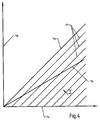
- FIG. 4 shows the functional dependency for a gas control device modified in this way between air flow and gas flow with different gas qualities again.
- Line 73 in Fig. 4 shows the ratio of gas pressure to air pressure or the ratio of that Burner 11 supplied gas flow and air flow for the worst (poorest) too expected gas quality.
- Air pressure is on the X-axis 75 and is on the Y-axis 76 Gas pressure applied.
- the linear drive 30 of the pressure regulator 34 again a maximum current I supplied.
- the gas regulator then works like a 1: 1 gas / air regulator. With an improved gas quality detected by the sensor 20 via the temperature controller 18 that is supplied to the linear drive 30 of the pressure controller 34 Current I reduced. The gas flow then decreases in relation to the air flow.
- Fig. 4 shows the functional dependency for a gas control device modified in this way between air flow and gas flow with different gas qualities again.
- Line 73 in Fig. 4 shows the ratio of gas pressure to air pressure or the ratio of that Burner 11 supplied gas flow and air flow for the worst (
- the constant pressure regulator 58 or the 1: 1 gas / air regulator can Gas control devices of the above-described embodiments by a Ratio pressure regulator or a 1: N gas / air regulator can be replaced.
Landscapes
- Engineering & Computer Science (AREA)
- Chemical & Material Sciences (AREA)
- Combustion & Propulsion (AREA)
- Mechanical Engineering (AREA)
- General Engineering & Computer Science (AREA)
- Regulation And Control Of Combustion (AREA)
Applications Claiming Priority (2)
| Application Number | Priority Date | Filing Date | Title |
|---|---|---|---|
| DE19821853 | 1998-05-15 | ||
| DE19821853A DE19821853C1 (de) | 1998-05-15 | 1998-05-15 | Regeleinrichtung für Gasbrenner |
Publications (3)
| Publication Number | Publication Date |
|---|---|
| EP0957314A2 true EP0957314A2 (fr) | 1999-11-17 |
| EP0957314A3 EP0957314A3 (fr) | 2002-03-13 |
| EP0957314B1 EP0957314B1 (fr) | 2006-01-04 |
Family
ID=7867896
Family Applications (1)
| Application Number | Title | Priority Date | Filing Date |
|---|---|---|---|
| EP99109002A Expired - Lifetime EP0957314B1 (fr) | 1998-05-15 | 1999-05-06 | Dispositif de commande pour des brûleurs à gaz |
Country Status (2)
| Country | Link |
|---|---|
| EP (1) | EP0957314B1 (fr) |
| DE (2) | DE19821853C1 (fr) |
Cited By (5)
| Publication number | Priority date | Publication date | Assignee | Title |
|---|---|---|---|---|
| WO2005073632A1 (fr) * | 2004-01-28 | 2005-08-11 | Sit La Precisa S.P.A. | Unite de soupape multifonction controlant la fourniture de gaz combustible a un bruleur |
| EP1959326A4 (fr) * | 2005-12-05 | 2012-01-11 | Siemens Building Tech Ag | Dispositif regulateur |
| EP3499124A1 (fr) * | 2017-12-12 | 2019-06-19 | Robert Bosch GmbH | Composant d'appareil de chauffage et procédé de réglage d'un débit volumétrique de carburant |
| CN112610729A (zh) * | 2020-12-29 | 2021-04-06 | 广东万和新电气股份有限公司 | 空燃比例阀及燃气热水设备 |
| CN116981884A (zh) * | 2021-03-04 | 2023-10-31 | 彼特威有限责任公司 | 部分预混合的燃气燃烧器器具 |
Families Citing this family (16)
| Publication number | Priority date | Publication date | Assignee | Title |
|---|---|---|---|---|
| AT408271B (de) * | 1999-05-25 | 2001-10-25 | Vaillant Gmbh | Einrichtung zur einstellung der gasart für eine heizeinrichtung |
| DE10017990C2 (de) * | 2000-04-11 | 2002-03-07 | Viessmann Werke Kg | Gasgebläsebrenner |
| DE10022882B4 (de) * | 2000-05-10 | 2010-04-29 | Loi Thermprocess Gmbh | Verfahren und Vorrichtung zum Regeln eines Brenners |
| DE10026035C2 (de) * | 2000-05-25 | 2002-06-27 | Honeywell Bv | Regeleinrichtung für Gasbrenner |
| DE10209193C1 (de) * | 2002-03-04 | 2003-11-20 | Heatec Thermotechnik Gmbh | Elektrisch steuerbares Gasventil |
| DE10232647B4 (de) * | 2002-07-18 | 2004-05-13 | Honeywell B.V. | Regeleinrichtung für Gasbrenner |
| DE10232654B3 (de) | 2002-07-18 | 2004-03-11 | Honeywell B.V. | Gasdurchflussregeleinrichtung |
| DE10232653B3 (de) | 2002-07-18 | 2004-03-11 | Honeywell B.V. | Regeleinrichtung für Gasbrenner |
| DE102006036294A1 (de) * | 2006-08-03 | 2008-02-07 | Inter Control Hermann Köhler Elektrik GmbH & Co. KG | Gasventil und Verfahren zur Ansteuerung eines Gasventils |
| US7950622B2 (en) | 2007-07-25 | 2011-05-31 | Honeywell International, Inc. | System, apparatus and method for controlling valves |
| DE102008024843A1 (de) | 2008-05-23 | 2009-11-26 | Honeywell Technologies S.A.R.L. | Gasregelgerät |
| DE202010015938U1 (de) | 2010-11-30 | 2011-02-10 | Honeywell Technologies Sarl | Gasregelgerät |
| DE102013003524B4 (de) | 2013-03-04 | 2022-07-14 | Pittway Sàrl | Gasregelgerät |
| EP2868970B1 (fr) | 2013-10-29 | 2020-04-22 | Honeywell Technologies Sarl | Dispositif de régulation |
| DE102018121844A1 (de) * | 2018-09-07 | 2020-03-12 | Vaillant Gmbh | Gasventil |
| CN111075984B (zh) * | 2020-01-14 | 2022-02-22 | 嘉兴市大宇机电有限公司 | 一种校零空燃比例电磁阀 |
Citations (3)
| Publication number | Priority date | Publication date | Assignee | Title |
|---|---|---|---|---|
| EP0103303A2 (fr) | 1982-09-15 | 1984-03-21 | Joh. Vaillant GmbH u. Co. | Source de chaleur chauffée au combustible |
| EP0390964A2 (fr) | 1989-04-07 | 1990-10-10 | Honeywell B.V. | Dispositif de commande pour brûleur à gaz |
| DE4230201A1 (de) | 1991-09-09 | 1993-03-11 | Vaillant Joh Gmbh & Co | Servodruckregler |
Family Cites Families (2)
| Publication number | Priority date | Publication date | Assignee | Title |
|---|---|---|---|---|
| DE4343306A1 (de) * | 1993-12-17 | 1995-06-22 | Gastechnic Prod Vertriebges | Verfahren und Vorrichtung zur Regelung des Druckes in einer Gasleitung |
| IT1274622B (it) * | 1994-08-17 | 1997-07-18 | Integra Srl | Gruppo valvolare per caldaie a gas |
-
1998
- 1998-05-15 DE DE19821853A patent/DE19821853C1/de not_active Expired - Lifetime
-
1999
- 1999-05-06 EP EP99109002A patent/EP0957314B1/fr not_active Expired - Lifetime
- 1999-05-06 DE DE59913006T patent/DE59913006D1/de not_active Expired - Lifetime
Patent Citations (3)
| Publication number | Priority date | Publication date | Assignee | Title |
|---|---|---|---|---|
| EP0103303A2 (fr) | 1982-09-15 | 1984-03-21 | Joh. Vaillant GmbH u. Co. | Source de chaleur chauffée au combustible |
| EP0390964A2 (fr) | 1989-04-07 | 1990-10-10 | Honeywell B.V. | Dispositif de commande pour brûleur à gaz |
| DE4230201A1 (de) | 1991-09-09 | 1993-03-11 | Vaillant Joh Gmbh & Co | Servodruckregler |
Cited By (5)
| Publication number | Priority date | Publication date | Assignee | Title |
|---|---|---|---|---|
| WO2005073632A1 (fr) * | 2004-01-28 | 2005-08-11 | Sit La Precisa S.P.A. | Unite de soupape multifonction controlant la fourniture de gaz combustible a un bruleur |
| EP1959326A4 (fr) * | 2005-12-05 | 2012-01-11 | Siemens Building Tech Ag | Dispositif regulateur |
| EP3499124A1 (fr) * | 2017-12-12 | 2019-06-19 | Robert Bosch GmbH | Composant d'appareil de chauffage et procédé de réglage d'un débit volumétrique de carburant |
| CN112610729A (zh) * | 2020-12-29 | 2021-04-06 | 广东万和新电气股份有限公司 | 空燃比例阀及燃气热水设备 |
| CN116981884A (zh) * | 2021-03-04 | 2023-10-31 | 彼特威有限责任公司 | 部分预混合的燃气燃烧器器具 |
Also Published As
| Publication number | Publication date |
|---|---|
| EP0957314A3 (fr) | 2002-03-13 |
| DE59913006D1 (de) | 2006-03-30 |
| EP0957314B1 (fr) | 2006-01-04 |
| DE19821853C1 (de) | 1999-07-29 |
Similar Documents
| Publication | Publication Date | Title |
|---|---|---|
| DE19821853C1 (de) | Regeleinrichtung für Gasbrenner | |
| DE19515286C2 (de) | Druckregler zum Erzeugen eines geregelten Steuerdrucks für ein membrangesteuertes Gasventil | |
| EP0644377B1 (fr) | Dispositif de commande pour brûleur à gaz | |
| EP1744102B1 (fr) | Brûleur à gaz | |
| EP0062854B1 (fr) | Dispositif de chauffage à gaz pour eau ou air | |
| DE19740666C1 (de) | Regelvorrichtung für das Einhalten eines geforderten Gas-/Luft-Verhältnisses für Gasbrenner | |
| EP0652501B1 (fr) | Appareil de positionnement multiple avec régulateur d'entrée | |
| DE102019101357B4 (de) | Anordnung zum zweistufigen Lufteinlassen und -auslassen für elektrisch gesteuerte Proportionalventile | |
| DE2649665A1 (de) | Langsam oeffnendes gasventil | |
| DE3911268A1 (de) | Regeleinrichtung fuer gasbrenner | |
| DE19501749C2 (de) | Verfahren und Vorrichtung zum Steuern eines Gas-Gebläsebrenners | |
| DE29808799U1 (de) | Regeleinrichtung für Gasbrenner | |
| EP0062856B1 (fr) | Dispositif de régulation pour une chaudière à gaz d'une installation de chauffage à eau chaude | |
| EP1635066B1 (fr) | Installation d'alimentation en gaz et procédé d'utilisation associé pour une turbine à gaz | |
| DE2723178C2 (de) | Sicherheits- und Steuersystem für die Luftzufuhr zur Verbrennungskammer eines Gasbrenners mit Zwangsabzug | |
| EP0103303A2 (fr) | Source de chaleur chauffée au combustible | |
| EP0036613B1 (fr) | Dispositif de régulation pour un échauffeur à eau ou air à combustion gazeuse pouvant être commandé par un capteur de température | |
| EP0109978A1 (fr) | Appareil de régulation de gaz avec un servorégulateur de pression | |
| EP0866270B1 (fr) | Appareil de chauffage à gaz, notamment un chauffe-eau | |
| DE10022882B4 (de) | Verfahren und Vorrichtung zum Regeln eines Brenners | |
| EP1305553A1 (fr) | Systeme de combustion pour un appareil de cuisson et appareil de cuisson pourvu d'un tel systeme de combustion | |
| EP0036610B1 (fr) | Procédé de fonctionnement d'une source de chaleur chauffée par combustible | |
| DE2719523C3 (de) | Gasventil | |
| EP0108349A2 (fr) | Source de chaleur chauffée au gaz | |
| DE3010737A1 (de) | Gasregelgeraet fuer brenner |
Legal Events
| Date | Code | Title | Description |
|---|---|---|---|
| PUAI | Public reference made under article 153(3) epc to a published international application that has entered the european phase |
Free format text: ORIGINAL CODE: 0009012 |
|
| AK | Designated contracting states |
Kind code of ref document: A2 Designated state(s): AT BE CH CY DE DK ES FI FR GB GR IE IT LI LU MC NL PT SE Kind code of ref document: A2 Designated state(s): DE FR GB IT NL |
|
| AX | Request for extension of the european patent |
Free format text: AL;LT;LV;MK;RO;SI |
|
| PUAL | Search report despatched |
Free format text: ORIGINAL CODE: 0009013 |
|
| AK | Designated contracting states |
Kind code of ref document: A3 Designated state(s): AT BE CH CY DE DK ES FI FR GB GR IE IT LI LU MC NL PT SE |
|
| AX | Request for extension of the european patent |
Free format text: AL;LT;LV;MK;RO;SI |
|
| RIC1 | Information provided on ipc code assigned before grant |
Free format text: 7F 23N 1/02 A, 7F 23N 5/18 B |
|
| 17P | Request for examination filed |
Effective date: 20020522 |
|
| AKX | Designation fees paid |
Free format text: DE FR GB IT NL |
|
| 17Q | First examination report despatched |
Effective date: 20040326 |
|
| GRAP | Despatch of communication of intention to grant a patent |
Free format text: ORIGINAL CODE: EPIDOSNIGR1 |
|
| GRAS | Grant fee paid |
Free format text: ORIGINAL CODE: EPIDOSNIGR3 |
|
| GRAA | (expected) grant |
Free format text: ORIGINAL CODE: 0009210 |
|
| AK | Designated contracting states |
Kind code of ref document: B1 Designated state(s): DE FR GB IT NL |
|
| REG | Reference to a national code |
Ref country code: GB Ref legal event code: FG4D Free format text: NOT ENGLISH |
|
| GBT | Gb: translation of ep patent filed (gb section 77(6)(a)/1977) |
Effective date: 20060104 |
|
| REF | Corresponds to: |
Ref document number: 59913006 Country of ref document: DE Date of ref document: 20060330 Kind code of ref document: P |
|
| ET | Fr: translation filed | ||
| PLBE | No opposition filed within time limit |
Free format text: ORIGINAL CODE: 0009261 |
|
| STAA | Information on the status of an ep patent application or granted ep patent |
Free format text: STATUS: NO OPPOSITION FILED WITHIN TIME LIMIT |
|
| 26N | No opposition filed |
Effective date: 20061005 |
|
| REG | Reference to a national code |
Ref country code: GB Ref legal event code: 732E |
|
| NLS | Nl: assignments of ep-patents |
Owner name: HONEYWELL TECHNOLOGIES SARL Effective date: 20080618 |
|
| REG | Reference to a national code |
Ref country code: FR Ref legal event code: TP |
|
| PGFP | Annual fee paid to national office [announced via postgrant information from national office to epo] |
Ref country code: NL Payment date: 20120515 Year of fee payment: 14 Ref country code: DE Payment date: 20120531 Year of fee payment: 14 |
|
| PGFP | Annual fee paid to national office [announced via postgrant information from national office to epo] |
Ref country code: GB Payment date: 20120426 Year of fee payment: 14 Ref country code: FR Payment date: 20120510 Year of fee payment: 14 |
|
| PGFP | Annual fee paid to national office [announced via postgrant information from national office to epo] |
Ref country code: IT Payment date: 20120518 Year of fee payment: 14 |
|
| REG | Reference to a national code |
Ref country code: NL Ref legal event code: V1 Effective date: 20131201 |
|
| GBPC | Gb: european patent ceased through non-payment of renewal fee |
Effective date: 20130506 |
|
| PG25 | Lapsed in a contracting state [announced via postgrant information from national office to epo] |
Ref country code: DE Free format text: LAPSE BECAUSE OF NON-PAYMENT OF DUE FEES Effective date: 20131203 |
|
| PG25 | Lapsed in a contracting state [announced via postgrant information from national office to epo] |
Ref country code: IT Free format text: LAPSE BECAUSE OF NON-PAYMENT OF DUE FEES Effective date: 20130506 Ref country code: NL Free format text: LAPSE BECAUSE OF NON-PAYMENT OF DUE FEES Effective date: 20131201 |
|
| REG | Reference to a national code |
Ref country code: DE Ref legal event code: R119 Ref document number: 59913006 Country of ref document: DE Effective date: 20131203 |
|
| REG | Reference to a national code |
Ref country code: FR Ref legal event code: ST Effective date: 20140131 |
|
| PG25 | Lapsed in a contracting state [announced via postgrant information from national office to epo] |
Ref country code: GB Free format text: LAPSE BECAUSE OF NON-PAYMENT OF DUE FEES Effective date: 20130506 |
|
| PG25 | Lapsed in a contracting state [announced via postgrant information from national office to epo] |
Ref country code: FR Free format text: LAPSE BECAUSE OF NON-PAYMENT OF DUE FEES Effective date: 20130531 |