EP0957571A2 - Amplification du couple pour brise-glace dans un moteur-couple électrique - Google Patents
Amplification du couple pour brise-glace dans un moteur-couple électrique Download PDFInfo
- Publication number
- EP0957571A2 EP0957571A2 EP99109073A EP99109073A EP0957571A2 EP 0957571 A2 EP0957571 A2 EP 0957571A2 EP 99109073 A EP99109073 A EP 99109073A EP 99109073 A EP99109073 A EP 99109073A EP 0957571 A2 EP0957571 A2 EP 0957571A2
- Authority
- EP
- European Patent Office
- Prior art keywords
- torque
- rotor
- motor
- torque motor
- output
- Prior art date
- Legal status (The legal status is an assumption and is not a legal conclusion. Google has not performed a legal analysis and makes no representation as to the accuracy of the status listed.)
- Withdrawn
Links
Images


Classifications
-
- H—ELECTRICITY
- H02—GENERATION; CONVERSION OR DISTRIBUTION OF ELECTRIC POWER
- H02K—DYNAMO-ELECTRIC MACHINES
- H02K26/00—Machines adapted to function as torque motors, i.e. to exert a torque when stalled
-
- F—MECHANICAL ENGINEERING; LIGHTING; HEATING; WEAPONS; BLASTING
- F02—COMBUSTION ENGINES; HOT-GAS OR COMBUSTION-PRODUCT ENGINE PLANTS
- F02D—CONTROLLING COMBUSTION ENGINES
- F02D11/00—Arrangements for, or adaptations to, non-automatic engine control initiation means, e.g. operator initiated
- F02D11/06—Arrangements for, or adaptations to, non-automatic engine control initiation means, e.g. operator initiated characterised by non-mechanical control linkages, e.g. fluid control linkages or by control linkages with power drive or assistance
- F02D11/10—Arrangements for, or adaptations to, non-automatic engine control initiation means, e.g. operator initiated characterised by non-mechanical control linkages, e.g. fluid control linkages or by control linkages with power drive or assistance of the electric type
- F02D11/107—Safety-related aspects
-
- G—PHYSICS
- G05—CONTROLLING; REGULATING
- G05D—SYSTEMS FOR CONTROLLING OR REGULATING NON-ELECTRIC VARIABLES
- G05D17/00—Control of torque; Control of mechanical power
- G05D17/02—Control of torque; Control of mechanical power characterised by the use of electric means
-
- F—MECHANICAL ENGINEERING; LIGHTING; HEATING; WEAPONS; BLASTING
- F02—COMBUSTION ENGINES; HOT-GAS OR COMBUSTION-PRODUCT ENGINE PLANTS
- F02D—CONTROLLING COMBUSTION ENGINES
- F02D11/00—Arrangements for, or adaptations to, non-automatic engine control initiation means, e.g. operator initiated
- F02D11/06—Arrangements for, or adaptations to, non-automatic engine control initiation means, e.g. operator initiated characterised by non-mechanical control linkages, e.g. fluid control linkages or by control linkages with power drive or assistance
- F02D11/10—Arrangements for, or adaptations to, non-automatic engine control initiation means, e.g. operator initiated characterised by non-mechanical control linkages, e.g. fluid control linkages or by control linkages with power drive or assistance of the electric type
- F02D2011/108—Arrangements for, or adaptations to, non-automatic engine control initiation means, e.g. operator initiated characterised by non-mechanical control linkages, e.g. fluid control linkages or by control linkages with power drive or assistance of the electric type with means for detecting or resolving a stuck throttle, e.g. when being frozen in a position
-
- F—MECHANICAL ENGINEERING; LIGHTING; HEATING; WEAPONS; BLASTING
- F05—INDEXING SCHEMES RELATING TO ENGINES OR PUMPS IN VARIOUS SUBCLASSES OF CLASSES F01-F04
- F05C—INDEXING SCHEME RELATING TO MATERIALS, MATERIAL PROPERTIES OR MATERIAL CHARACTERISTICS FOR MACHINES, ENGINES OR PUMPS OTHER THAN NON-POSITIVE-DISPLACEMENT MACHINES OR ENGINES
- F05C2201/00—Metals
- F05C2201/02—Light metals
- F05C2201/021—Aluminium
Definitions
- the present invention relates to motors of the fractional revolution type or torque motors as they are commonly called.
- Motors of this type typically provide angular displacement or movement of the rotor based on an applied electrical signal as, for example, angular rotor movement proportional to the applied voltage or level of current flow through the motor winding.
- the invention may have broader applications wherever a particular vibration is advantageously used to assure a desired movement.
- Torque motors have found widespread application in control systems where it is desired to rotate a shaft or member to a specific position or to apply a specified amount of torque to a shaft in response to an electrical control signal.
- torque motors have been utilized to control the position of an internal combustion engine air inlet throttle valve by an electrical signal instead of directly by user movement of a mechanical throttle linkage attached to the throttle valve.
- electrical engine throttle valve control has arisen in certain motor vehicle applications where it is desired to provide cruise control and/or override the user input to the throttle position control mechanism in response to the vehicle encountering extreme driving conditions or emergency situations.
- a method of amplifying the torque output by an electric torque motor of a mechanical system is provided.
- the torque is amplified from a normal operating torque to an amplified torque sufficient to overcome an obstruction preventing movement of a rotor of the torque motor.
- the subject method includes applying one of a clockwise and a counter-clockwise direction torque to the rotor of the torque motor.
- the torque applied to the rotor is then reversed so that the other of the clockwise and counter-clockwise direction of torque is applied to the rotor.
- the foregoing torque-application steps are repeated in succession at a select frequency equal to the natural frequency of the mechanical system of which the motor is a part.
- the torque applied to the rotor is amplified by resonance to a level sufficient to overcome the ice or other obstruction.
- Another advantage of the present invention is found in the provision of a method of controlling a torque motor of a vehicle electronic throttle control system to overcome ice or another obstruction preventing movement of a throttle plate connected to rotate with the rotor of the torque motor.
- Still another advantage of the invention is that it allows for use of smaller, less expensive torque motors in electronic throttle control and other applications that have heretofore required larger, more expensive motors to overcome obstructions of components connected to the rotor.
- the invention may take form in certain parts and arrangements of parts, and in certain steps and arrangements of steps, preferred embodiments of which are illustrated herein.
- the drawings are only for purposes of illustrating preferred embodiments and are not to be construed as limiting the invention.
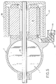
- FIGURES 1 and 2 illustrate one suitable torque motor 10 of the type used to control the position of a throttle plate in a vehicle electronic throttle control system.
- the invention will be explained with reference to the motor 10 , but those of ordinary skill in the art will recognize that the present invention is not limited to any particular torque motor, and other torque motors may be used in accordance with the present invention.
- Another suitable torque motor is described in a commonly assigned and co-pending U.S. patent application entitled “Torque Motor and Drive Circuit" in the name of David Turner filed on even date herewith by U.S. Express Mail.
- the motor 10 includes a base member 12 which has disposed therein a first bearing 14 illustrated as a ball bearing.
- a stator member 16 has four pole segments 18, 20, 22, 24 , and one end thereof registered against the base 12 in cantilever arrangement.
- a retaining member or spider cap 26 has a second bearing indicated generally at 28 received therein. The member 26 is registered against the free end of stator 16 and is secured by bolts 32 .
- An output shaft 34 is journaled through bearings 14, 23 and extends outwardly from the bearings. The end of the output shaft adjacent bearing 28 has securely attached thereto, such as by metal deformation or weldment, the closed end 36 of a generally cup-shaped rotor 38 which is nested over the stator 16 . As such, the output shaft 34 rotates with the rotor.
- a housing or cover 56 having a generally cup-shaped configuration is received over the rotor and attached to the base 12 by any suitable expedient.
- An electrical receptacle 58 is disposed on the base 12 and includes a pair of electrical terminal pins illustrated and denoted generally by reference numeral 60 . It will be understood that the pins are each connected to one end of the windings of each of the coils 40 through 46 .
- the flow of current through the windings 40-46 is controlled by an electronic control system 62 operatively connected to the motor via the plug 58 . As is discussed in further detail below, the control system 62 controls the flow of electrical current through the windings 40-46 to control the position of the rotor relative to the stator.
- the illustrated motor 10 is capable of providing a maximum of ⁇ ⁇ /4 radians of rotation with an overall length of 80 mm with an overall diameter of 62 mm and with 60 turns of number 20 gauge (0.79mm) magnet wire wound on each stator segment.
- the ability of the motor 10 to rotate the rotor 38 bi-directionally, i.e., in either a "clockwise” or "counter-clockwise” direction is required in order to function in accordance with the present invention. It has been found satisfactory to provide an air gap distance of about 0.5 - 1.0 mm radially between the stator segments 18-24 and the inner periphery of magnets 46-52 . For a motor having a stator length of 60 mm, a 0.75 mm air gap distance has proven satisfactory.
- stator coils are wound of copper magnet wire; however, it will be understood that aluminum or other materials may be employed if desired. It will also be understood that the torque motor 10 may be made with other combinations of stator and wire size and number of turns for the coils, and, the motor may be made to other sizes and configurations than the particular dimensions recited.
- the angular position of the throttle plate T is controlled by the torque motor 10 . More particularly, the output shaft 34 of the motor 10 is connected with the throttle plate T so that the plate rotates therewith and with the rotor 38 of the motor 10 .
- the throttle plate T is obstructed by ice or the like, the operator of the vehicle will be unable to control the position of the throttle plate, and thus the output of the internal combustion engine E .
- the case where the throttle plate T is seized by ice or other obstruction is schematically illustrated as a mechanical system S in FIGURE 4.
- the torque motor inertia J m is connected to the seized plate T via the shaft 34 having a select length L and diameter D .
- This mechanical system has a natural frequency that may be determined by conventional methods, for example, as follows:
- the controller 62 implements the torque amplification method in accordance with the present invention to energize the windings 40-46 so that a first clockwise or counter-clockwise torque is applied to the rotor 38 . Because the throttle plate T is unable to move, the shaft 34 is twisted or "wound-up" in the manner of a spring. Thereafter, the controller 62 energizes the windings 40-46 so that the opposite direction torque is applied to the rotor 38 .
Landscapes
- Engineering & Computer Science (AREA)
- Physics & Mathematics (AREA)
- General Physics & Mathematics (AREA)
- Automation & Control Theory (AREA)
- Chemical & Material Sciences (AREA)
- Combustion & Propulsion (AREA)
- Mechanical Engineering (AREA)
- General Engineering & Computer Science (AREA)
- Power Engineering (AREA)
- Reciprocating, Oscillating Or Vibrating Motors (AREA)
- Control Of Throttle Valves Provided In The Intake System Or In The Exhaust System (AREA)
- Control Of Stepping Motors (AREA)
- Apparatuses For Generation Of Mechanical Vibrations (AREA)
- Control Of Electric Motors In General (AREA)
- Control Of Motors That Do Not Use Commutators (AREA)
- Electric Propulsion And Braking For Vehicles (AREA)
Applications Claiming Priority (2)
| Application Number | Priority Date | Filing Date | Title |
|---|---|---|---|
| US09/076,352 US5912538A (en) | 1998-05-12 | 1998-05-12 | Torque amplification for ice breaking in an electric torque motor |
| US76352 | 2002-02-15 |
Publications (2)
| Publication Number | Publication Date |
|---|---|
| EP0957571A2 true EP0957571A2 (fr) | 1999-11-17 |
| EP0957571A3 EP0957571A3 (fr) | 2002-07-24 |
Family
ID=22131458
Family Applications (1)
| Application Number | Title | Priority Date | Filing Date |
|---|---|---|---|
| EP99109073A Withdrawn EP0957571A3 (fr) | 1998-05-12 | 1999-05-07 | Amplification du couple pour brise-glace dans un moteur-couple électrique |
Country Status (7)
| Country | Link |
|---|---|
| US (1) | US5912538A (fr) |
| EP (1) | EP0957571A3 (fr) |
| JP (1) | JPH11341873A (fr) |
| KR (1) | KR19990088100A (fr) |
| CN (1) | CN1235406A (fr) |
| BR (1) | BR9902142A (fr) |
| CA (1) | CA2272022A1 (fr) |
Families Citing this family (23)
| Publication number | Priority date | Publication date | Assignee | Title |
|---|---|---|---|---|
| US6037730A (en) * | 1998-11-12 | 2000-03-14 | Eaton Corporation | Degraded electronic throttle operation method and system |
| US6433448B1 (en) * | 1998-11-17 | 2002-08-13 | Eaton Corporation | Integrated torque motor and throttle body |
| US6431144B1 (en) | 1999-09-02 | 2002-08-13 | Siemens Vdo Automotive Inc. | Electronic throttle control system |
| AU1353101A (en) * | 1999-10-29 | 2001-05-14 | William C. Staker | Electronic throttle control pedal, position sensing device and assembly method |
| US6523433B1 (en) | 1999-11-23 | 2003-02-25 | William C. Staker | Electronic pedal assembly and method for providing a tuneable hysteresis force |
| US6857336B2 (en) | 1999-11-23 | 2005-02-22 | William C. Staker | Electronic pedal assembly and method for providing a tuneable hystersis force |
| DE10130117A1 (de) * | 2001-06-22 | 2003-01-30 | Minebea Co Ltd | Gehäusedeckel für einen Elektromotor, insbesondere für einen elektronisch kommutierten Gleichstrommotor |
| JP3948016B2 (ja) * | 2002-06-27 | 2007-07-25 | 株式会社デンソー | スロットル装置 |
| JP2005325741A (ja) * | 2004-05-13 | 2005-11-24 | Toyota Motor Corp | スロットル制御装置 |
| JP4462073B2 (ja) * | 2005-03-08 | 2010-05-12 | 株式会社デンソー | 車両用内燃機関の電子スロットル制御装置 |
| JP2007023933A (ja) * | 2005-07-19 | 2007-02-01 | Mitsubishi Electric Corp | 内燃機関の制御装置 |
| US7434566B2 (en) * | 2006-10-31 | 2008-10-14 | Delphi Technologies, Inc. | ETC control system and method |
| US20100100297A1 (en) * | 2008-10-20 | 2010-04-22 | Dan Nagashima | Method of reducing icing-related engine misfires |
| US8662569B2 (en) * | 2011-10-11 | 2014-03-04 | Ford Global Technologies, Llc | Dual torque active grille shutter for snow and ice |
| US9657632B2 (en) * | 2012-08-01 | 2017-05-23 | GM Global Technology Operations LLC | Method and apparatus for remote torque control of an aerodynamic air shutter mechanism |
| US9512662B1 (en) | 2015-05-15 | 2016-12-06 | Ford Global Technologies, Llc | Ice breaking strategy for vehicle side windows |
| CN106555687B (zh) * | 2015-09-30 | 2020-01-14 | 上海汽车集团股份有限公司 | 车辆发动机节气门阀板控制方法及装置 |
| CN106899161B (zh) * | 2015-12-21 | 2023-06-02 | 贵阳航空电机有限公司 | 力矩马达改进结构 |
| US10766624B2 (en) | 2016-01-20 | 2020-09-08 | Honeywell International Inc. | Algorithm for efficiently breaking a material |
| DE102018221491A1 (de) * | 2018-12-12 | 2020-06-18 | Robert Bosch Gmbh | Verfahren zum Betreiben einer elektrischen Maschine |
| US11372046B2 (en) * | 2019-09-10 | 2022-06-28 | GM Global Technology Operations LLC | Identification and mapping of fuel cell cathode valve ice breaking stall torque capability |
| CN112944614A (zh) * | 2021-03-01 | 2021-06-11 | 青岛海尔空调电子有限公司 | 空调的控制方法及空调 |
| CN114412702B (zh) * | 2022-01-21 | 2023-04-18 | 中国华能集团清洁能源技术研究院有限公司 | 一种风电机组和应对变桨轴承卡桨的优化方法 |
Family Cites Families (7)
| Publication number | Priority date | Publication date | Assignee | Title |
|---|---|---|---|---|
| JPS59188050A (ja) * | 1983-03-15 | 1984-10-25 | Mazda Motor Corp | エンジンのスロツトル制御装置 |
| US4715469A (en) * | 1985-08-29 | 1987-12-29 | Petrophysical Services, Inc. | Borehole seismic receiver |
| ES2019672B3 (es) * | 1987-04-09 | 1991-07-01 | Siemens Ag | Instalacion para el mando del aire de aspiracion en un motor de combustion interna |
| DE3743309A1 (de) * | 1987-12-21 | 1989-06-29 | Bosch Gmbh Robert | Verfahren und einrichtung zur erkennung und lockerung verklemmter stellelemente |
| US4850322A (en) * | 1988-03-31 | 1989-07-25 | Eaton Corporation | Method and apparatus for positioning a torque motor armature |
| JPH04169000A (ja) * | 1990-10-31 | 1992-06-17 | Ricoh Co Ltd | ステツピングモータ駆動装置 |
| EP0573964B1 (fr) * | 1992-06-08 | 1998-11-25 | Hewlett-Packard Company | Système pour générer un couple de rotation bipolaire agissant sur le disque d'un lecteur de disque pour libérer des transducteurs collés |
-
1998
- 1998-05-12 US US09/076,352 patent/US5912538A/en not_active Expired - Lifetime
-
1999
- 1999-05-07 EP EP99109073A patent/EP0957571A3/fr not_active Withdrawn
- 1999-05-07 KR KR1019990016269A patent/KR19990088100A/ko not_active Withdrawn
- 1999-05-11 CA CA002272022A patent/CA2272022A1/fr not_active Abandoned
- 1999-05-11 BR BR9902142-0A patent/BR9902142A/pt not_active IP Right Cessation
- 1999-05-12 JP JP11131339A patent/JPH11341873A/ja active Pending
- 1999-05-12 CN CN99106391A patent/CN1235406A/zh active Pending
Also Published As
| Publication number | Publication date |
|---|---|
| CN1235406A (zh) | 1999-11-17 |
| CA2272022A1 (fr) | 1999-11-12 |
| US5912538A (en) | 1999-06-15 |
| EP0957571A3 (fr) | 2002-07-24 |
| KR19990088100A (ko) | 1999-12-27 |
| JPH11341873A (ja) | 1999-12-10 |
| BR9902142A (pt) | 2000-01-18 |
Similar Documents
| Publication | Publication Date | Title |
|---|---|---|
| US5912538A (en) | Torque amplification for ice breaking in an electric torque motor | |
| US6518683B2 (en) | Integrated torque motor and throttle body | |
| CN1134796C (zh) | 用于致动一个控制部件的装置 | |
| US4779592A (en) | Stepping motor and intake control apparatus therewith | |
| JP3007153B2 (ja) | 回転調節器 | |
| KR20000017432A (ko) | 토오크 모터 및 그 제조 방법 | |
| CN105308287A (zh) | 用于燃烧发动机的增压设备 | |
| US6332451B1 (en) | Rotary valve actuator arrangement | |
| JP2000014062A (ja) | トルクモータ | |
| KR0171904B1 (ko) | 전자기 회전 작동기 | |
| MXPA99004349A (es) | Amplificacion de torsion para ruptura de hielo en un motor electrico de torsion | |
| US6239562B1 (en) | Claw type torque motor and throttle valve employing same | |
| EP1002943A2 (fr) | Corps de papillon avec moteur-couple intégré | |
| EP1146625A2 (fr) | Machine électrique tournante | |
| JP3408096B2 (ja) | エンジン用弁装置 | |
| JP2000116095A (ja) | トルクモータおよびそれを用いたスロットル装置 | |
| JPH09112299A (ja) | スロットル弁制御装置 | |
| MXPA99010536A (en) | Torsion engine and body of integrated string, improved | |
| EP0957567A2 (fr) | Moteur-couple et circuit de commande | |
| JPH11299209A (ja) | トルクモータ | |
| JP2000152533A (ja) | トルクモータ | |
| JPH11299208A (ja) | トルクモータ | |
| JP2001182561A (ja) | スロットル装置 | |
| JP2001173462A (ja) | スロットル制御装置 | |
| JPH11146624A (ja) | 電動機 |
Legal Events
| Date | Code | Title | Description |
|---|---|---|---|
| PUAI | Public reference made under article 153(3) epc to a published international application that has entered the european phase |
Free format text: ORIGINAL CODE: 0009012 |
|
| AK | Designated contracting states |
Kind code of ref document: A2 Designated state(s): AT BE CH CY DE DK ES FI FR GB GR IE IT LI LU MC NL PT SE |
|
| AX | Request for extension of the european patent |
Free format text: AL;LT;LV;MK;RO;SI |
|
| PUAL | Search report despatched |
Free format text: ORIGINAL CODE: 0009013 |
|
| AK | Designated contracting states |
Kind code of ref document: A3 Designated state(s): AT BE CH CY DE DK ES FI FR GB GR IE IT LI LU MC NL PT SE |
|
| AX | Request for extension of the european patent |
Free format text: AL;LT;LV;MK;RO;SI |
|
| 17P | Request for examination filed |
Effective date: 20020821 |
|
| AKX | Designation fees paid |
Designated state(s): DE ES FR GB IT SE |
|
| 17Q | First examination report despatched |
Effective date: 20030403 |
|
| STAA | Information on the status of an ep patent application or granted ep patent |
Free format text: STATUS: THE APPLICATION IS DEEMED TO BE WITHDRAWN |
|
| 18D | Application deemed to be withdrawn |
Effective date: 20030916 |