EP0958877A2 - Plattenschneidmaschine zum Abtrennen einer Platte,die Polymerteilchen enthält mit einer Abmessung grösser als die Dicke der Platte - Google Patents
Plattenschneidmaschine zum Abtrennen einer Platte,die Polymerteilchen enthält mit einer Abmessung grösser als die Dicke der Platte Download PDFInfo
- Publication number
- EP0958877A2 EP0958877A2 EP99103887A EP99103887A EP0958877A2 EP 0958877 A2 EP0958877 A2 EP 0958877A2 EP 99103887 A EP99103887 A EP 99103887A EP 99103887 A EP99103887 A EP 99103887A EP 0958877 A2 EP0958877 A2 EP 0958877A2
- Authority
- EP
- European Patent Office
- Prior art keywords
- blade
- workpiece
- slicing
- sheets
- inches
- Prior art date
- Legal status (The legal status is an assumption and is not a legal conclusion. Google has not performed a legal analysis and makes no representation as to the accuracy of the status listed.)
- Withdrawn
Links
Images


Classifications
-
- B—PERFORMING OPERATIONS; TRANSPORTING
- B26—HAND CUTTING TOOLS; CUTTING; SEVERING
- B26D—CUTTING; DETAILS COMMON TO MACHINES FOR PERFORATING, PUNCHING, CUTTING-OUT, STAMPING-OUT OR SEVERING
- B26D1/00—Cutting through work characterised by the nature or movement of the cutting member or particular materials not otherwise provided for; Apparatus or machines therefor; Cutting members therefor
- B26D1/01—Cutting through work characterised by the nature or movement of the cutting member or particular materials not otherwise provided for; Apparatus or machines therefor; Cutting members therefor involving a cutting member which does not travel with the work
- B26D1/46—Cutting through work characterised by the nature or movement of the cutting member or particular materials not otherwise provided for; Apparatus or machines therefor; Cutting members therefor involving a cutting member which does not travel with the work having an endless band-knife or the like
-
- B—PERFORMING OPERATIONS; TRANSPORTING
- B23—MACHINE TOOLS; METAL-WORKING NOT OTHERWISE PROVIDED FOR
- B23D—PLANING; SLOTTING; SHEARING; BROACHING; SAWING; FILING; SCRAPING; LIKE OPERATIONS FOR WORKING METAL BY REMOVING MATERIAL, NOT OTHERWISE PROVIDED FOR
- B23D55/00—Sawing machines or sawing devices working with strap saw blades, characterised only by constructional features of particular parts
- B23D55/04—Sawing machines or sawing devices working with strap saw blades, characterised only by constructional features of particular parts of devices for feeding or clamping work
- B23D55/046—Sawing machines or sawing devices working with strap saw blades, characterised only by constructional features of particular parts of devices for feeding or clamping work for feeding work into engagement with the saw blade
-
- Y—GENERAL TAGGING OF NEW TECHNOLOGICAL DEVELOPMENTS; GENERAL TAGGING OF CROSS-SECTIONAL TECHNOLOGIES SPANNING OVER SEVERAL SECTIONS OF THE IPC; TECHNICAL SUBJECTS COVERED BY FORMER USPC CROSS-REFERENCE ART COLLECTIONS [XRACs] AND DIGESTS
- Y10—TECHNICAL SUBJECTS COVERED BY FORMER USPC
- Y10T—TECHNICAL SUBJECTS COVERED BY FORMER US CLASSIFICATION
- Y10T83/00—Cutting
- Y10T83/283—With means to control or modify temperature of apparatus or work
- Y10T83/293—Of tool
-
- Y—GENERAL TAGGING OF NEW TECHNOLOGICAL DEVELOPMENTS; GENERAL TAGGING OF CROSS-SECTIONAL TECHNOLOGIES SPANNING OVER SEVERAL SECTIONS OF THE IPC; TECHNICAL SUBJECTS COVERED BY FORMER USPC CROSS-REFERENCE ART COLLECTIONS [XRACs] AND DIGESTS
- Y10—TECHNICAL SUBJECTS COVERED BY FORMER USPC
- Y10T—TECHNICAL SUBJECTS COVERED BY FORMER US CLASSIFICATION
- Y10T83/00—Cutting
- Y10T83/707—By endless band or chain knife
- Y10T83/7226—With means to guard the tension
-
- Y—GENERAL TAGGING OF NEW TECHNOLOGICAL DEVELOPMENTS; GENERAL TAGGING OF CROSS-SECTIONAL TECHNOLOGIES SPANNING OVER SEVERAL SECTIONS OF THE IPC; TECHNICAL SUBJECTS COVERED BY FORMER USPC CROSS-REFERENCE ART COLLECTIONS [XRACs] AND DIGESTS
- Y10—TECHNICAL SUBJECTS COVERED BY FORMER USPC
- Y10T—TECHNICAL SUBJECTS COVERED BY FORMER US CLASSIFICATION
- Y10T83/00—Cutting
- Y10T83/707—By endless band or chain knife
- Y10T83/7264—With special blade guide means
-
- Y—GENERAL TAGGING OF NEW TECHNOLOGICAL DEVELOPMENTS; GENERAL TAGGING OF CROSS-SECTIONAL TECHNOLOGIES SPANNING OVER SEVERAL SECTIONS OF THE IPC; TECHNICAL SUBJECTS COVERED BY FORMER USPC CROSS-REFERENCE ART COLLECTIONS [XRACs] AND DIGESTS
- Y10—TECHNICAL SUBJECTS COVERED BY FORMER USPC
- Y10T—TECHNICAL SUBJECTS COVERED BY FORMER US CLASSIFICATION
- Y10T83/00—Cutting
- Y10T83/929—Tool or tool with support
- Y10T83/9317—Endless band or belt type
Definitions
- the present invention relates to apparatus for slicing a workpiece into sheets and more particularly to apparatus used to cut polymer compositions produced in slabs or sheets and meant to simulate, for example, stone such as marble or granite.
- the present invention further relates to apparatus for slicing such slabs into sheets.
- Solid polymeric surfacing has a variety of uses, including household, commercial, and industrial uses in which durable, sometimes renewable, decorative surfaces are desired. Such surfaces include, but are not limited to, kitchen and other countertops, table tops, bathroom vanities, divider panels, and wall surfacing. These surfacing products may be produced so as to simulate stone such as marble or granite.
- U.S. Pats. No. 4,433, 070, and 4,446,177 disclose compositions for such products.
- U.S. Pat. No. 5,244,941 discloses a composition that is particularly useful as artificial stone surfacing, due to the inclusion of chips of a previously cured thermosetting resinous compound in the composition; also disclosed therein is the process for producing the surfacing. These products are typically produced in solid slabs about 1 ⁇ 2 inch in thickness. The result is surfacing of high quality, but relatively high cost.
- Lamellar, or disk-shaped, particles may be used, but with unacceptable results. Such particle shapes could have a maximum dimension that is greater than the sheet thickness and still fit within the sheet. However, the resin matrix typically is somewhat transparent, and the resultant effect from using lamellar shaped particles would not resemble the desirable "chunky" stone appearance. Instead the result would be oval and oblong particles that may partially disappear into the thickness of the sheet. Also, they may have a tendency to align during the sheet casting process, resulting in a less than random distribution of particles in the sheet.
- the only method of producing surfacing with a "chunky" look to date is by sanding or grinding relatively thick surfacing down in thickness to expose the interior (and thereby, a larger degree of flattened exposed surface area) of the particulate. This is necessary to produce a sheet with a surface look that is truly representative of the random nature of the particulate as dispersed in the resin matrix. As cast, the surface look of the slabs is not representative. Only the outer edges of the particulate approach the surface of the slab, and even then in only a tangential fashion. The random particulate pattern is not exposed until the sheet surface is sanded down.
- apparatus for slicing a workpiece into sheets, each sheet having a thickness the apparatus characterized by:
- the apparatus preferably includes at least two blade guides to stabilize the position of the blade relative to the workpiece.
- the blade is preferably under a tension of from about 7500 pounds per square inch (psi) to about 35000 psi.
- the blade may have a width of from about 2 inches to about 4 inches, the cutting edge may have from about 2 to about 4 teeth per inch, and the blade may have a kerf of from about .050 inches to about .075 inches.
- the blade preferably travels at a linear speed of from about 5000 feet per minute to about 10000 feet per minute.
- the method includes providing a solid polymeric slab, and cutting the slab into sheets of surfacing.
- the final thickness of the sheets may vary to a minimum of about 1/8 inch.
- the disclosed method may include the steps of providing a resin matrix syrup, providing relatively solid polymeric particles, coating the particles with an adhesion promoter, combining the particles and the syrup into a mixture, forming the mixture into a solidified slab, and cutting the slab into sheets of surfacing.
- the particles may have a maximum linear dimension that is greater than the final thickness of the sheets.
- a workpiece support member for supporting the workpiece during slicing
- a fluid supply for cooling the blade and workpiece during slicing
- a workpiece stabilizing member located between the support member and the blade.
- the workpiece-stabilizing member may be at least one set of pinch rollers, which preferably apply a pressure on the workpiece of from about 50 psi to about 100 psi, and more preferably from about 70 psi to about 90 psi.
- the workpiece has a longitudinal axis oriented perpendicular to a direction of blade travel during slicing.
- Workpiece guides maintain the longitudinal axis of the workpiece in a substantially perpendicular orientation to the direction of blade travel during slicing.
- the blade rides on a drive wheel and at least one idler wheel, which support and drive the blade.
- Each of these wheels preferably has a diameter of from about 24 inches to about 48 inches.
- a finished sheet after slicing has a maximum standard deviation in thickness of about .002 inches.
- the present method particularly allows the manufacture of solid surfacing veneer with a "chunky" appearance provided by the particulate in the surfacing.
- the "chunks" of particulate in the surface of the sheets have a maximum size or linear dimension that is greater than the thickness of the sheet.
- a portion of a sheet of veneer "V” is shown having particles A and B encased in resin matrix C.
- Maximum linear dimensions of particles A and B are A1 and B1 respectively, both dimensions being greater than sheet thickness "T".
- Thickness "T” is typically on the order of about 1/8 inches.
- this "chunky" look has only been achieved in sheets greater than 1 ⁇ 4 inch in thickness, and only through sanding or grinding a relatively substantial amount of material from the sheet surface, resulting in increased production time and cost, and increased wasted material.
- FIG. 2A shows a slab of solid surfacing veneer 10 in the "as cast” form.
- Prior art slabs of this type are usually made using a two-belt casting system as described, for example, in U.S. Pats. No. 3,371,383 and 3,376,371. Shown are resin matrix 12 and particulate 14. Note that the maximum diameter of each piece of particulate 14 may not be greater than sheet thickness "T", or bulges would result in sheet 10 where particulate 14 extended out past surface "S" of slab 10; such bulges would interfere with the casting process and result in unacceptable product.
- Line F-F denotes the depth to which surface "S" is sanded to help expose a portion of the particulate thereby bringing out the artificial stone appearance. Note in Figure 2B that only a small amount of the particulate interior may be exposed by this prior art method. The result is an artificial stone appearance, but with a relatively small granular pattern.
- Figure 3A shows a piece of the relatively thick prior art solid surfacing which may contain larger sized particles because of the greater sheet thickness. To expose a large amount of particle interior, the surface of the slab must be ground down to the level at line F-F. The result is still a relatively thick and expensive product. The result is also a chunky appearance, as demonstrated by Figure 3B, but at the expense of increased manufacturing time and cost, and substantial wasted material.
- Figure 4A shows a slab of artificial stone of the present invention.
- Particulate may be of a diameter as great as the slab thickness.
- Figure 4B By slicing the slab through its thickness, multiple sheets of solid surface veneer are produced, as shown in Figure 4B. Note that because the particulate is sliced through its interior, the result is a "chunky" appearance without the need for the excessive surface grinding necessary in the prior art method to produce a similar appearance.
- a slab of about 1 ⁇ 2 inch in thickness may be sliced into 3 sheets of veneer each about 1/8 inch in thickness, accounting for material lost in the slicing operation. The material lost in the slicing operation is still a great reduction in waste over the prior art method of producing the "chunky" appearance.
- FIGS. 5A and 5B show an alternative of the present invention in which the size of a majority of the particulate used in the slab approaches the thickness of the slab. The result is a sheet of veneer with a "super-chunky" appearance.
- the present method may be used to overcome the problems described above in cutting sheets of various thicknesses from about 1/8 inches up to about 1/2 inches, or more if the specific application for thicker sheets warrants such.
- a 2 inch thick slab of solid polymeric surfacing may be sliced into three sheets of about, or a little less than, 1 ⁇ 2 inches in thickness, and three sheets of about, or a little less than, 1/8 inches in thickness, accounting for material lost during slicing.
- the present method achieves a chunky surface appearance without excessive surface grinding and wasted material.
- the particles that are added to the resin matrix to achieve the "chunky" artificial stone appearance may be composed of many different material types.
- particles may be made of thermoplastic resins such as acrylic resins, acrylic blends with polycarbonate or polystyrene, polyesters, polyamides, and polyolefins.
- Particles may also be made of thermoset resins such as unsaturated polyesters and blends with acrylics or polyvinylacetates or polystyrenes, melamine formaldehyde, phenol formaldehyde, epoxies, and vinyl esters.
- Particles may additionally be of organometallic resins such as the thermoplastics and thermosets listed above along with sol gel resins based on tetraethoxyortho silicate or triethoxy aluminate or tetralkoxy titanates.
- particles may be composed of minerals like granite, marble, or quartz, or may be man made glass, ceramics, sol gels, or cement.
- the resin matrix may also be composed of many different material types.
- the resin matrix may be made of thermoplastic resins such as acrylic resins, acrylic blends with polycarbonate or polystyrene, polyesters, polyamides, and polyolefins.
- the matrix may also be made of thermoset resins such as unsaturated polyesters and blends with acrylics or polyvinylacetates or polystyrenes, melamine formaldehyde, phenol formaldehyde, epoxies, and vinyl esters.
- the matrix may additionally be of organometallic resins such as the thermoplastics and thermosets listed above along with sol gel resins based on tetraethoxyortho silicate or triethoxy aluminate or tetralkoxy titanates.
- the matrix may be composed of inorganics (e.g, cements).
- AMODEL 1460 is an engineering thermoplastic and is supplied in pellet form.
- the composition of the pellet is about 40% polyphthalamide resin and 60% wollastonite, a mineral filler known in the art. Pigments may be added to vary the color of the pellets, The weight percentage of wollastonite may be reduced to compensate for the addition of pigments.
- the pellets may be pulverized and sized according to the desired aesthetic effect in the final sheets of surfacing.
- the particles may be treated or coated with an adhesion promoter or coupling agent prior to being mixed with the resin matrix.
- the purpose of such coating is to promote adhesion between the surface of the particles and the resin matrix; in other words, the purpose is to form a bond between the particles and the matrix. This bond prevents gaps, inclusions, and the like from occurring between the particles and the resin matrix, which could initiate cracks, etc.
- Such treating is particularly important in the case of the present invention because inclusions in a slab of solid surfacing may result in stress cracking, crazing, and like defects after cutting though the slab, which will be disclosed in more detail below.
- adhesion promoters are the organofunctional silane products manufactured and sold by OSI of Tarrytown, NY (e.g, AMINO A-1100, METHACRYL A-172, and EPOXY A-187). These are dual-function molecules that contain an organofunctional group and a hydrolyzable group; they can react with a wide variety of organic and inorganic materials. They may be used as a filler treatment for improved filler-to-resin coupling and filler dispersion in thermoset and thermoplastic resins.
- the organofunctional silane sold by OSI under the trade name "AMINO A-1100", whose chemical name is gamma-aminopropyltriethoxysilane, is one adhesion promoter that is generally effective when coupling particles into an acrylic resin matrix.
- AMINO A-1100 whose chemical name is gamma-aminopropyltriethoxysilane
- Dow Coming produces silanes, e.g, Z-6020 diamino and Z-6040 epoxy.
- the particles are coated with the adhesion promoter in a twin-shell blender of the type sold by Patterson-Kelly Co. of East Stroudsburg, PA.
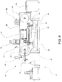
- Figures 6 - 10 An embodiment of the solid surfacing slicing saw of the present invention is shown in Figures 6 - 10.
- Figure 6 shows an elevational view of the front of saw 20, or the area of saw 20 that the polymeric slabs or workpieces would be fed into.
- the slabs would be fed into saw 20 lying flat, or horizontally, on a conveyor belt, but it is also anticipated that slabs could be fed into saw 20 in a vertical orientation if saw 20 were configured to accommodate such vertical orientation.
- Blade 22 rides on and is driven by drive wheel 24 and idler wheel 26.
- Blade 22 is preferably from about 2 inches to about 4 inches in width, and has a cutting edge with preferably from about 2 to about 4 teeth per inch.
- the blade is typically made of steel and the teeth are preferably carbide tipped.
- the preferred range of blade kerf i.e., the thickness of the cut made by blade 22
- blade 22 travels at a preferred linear speed of from about 5000 feet per minute to about 10000 feet per minute, while under a tension of from about 7500 pounds per square inch (psi) to about 35000 psi. More preferred ranges of speed and tension are from about 8000 feet per minute to about 9000 feet per minute, and from about 10000 psi to about 25000 psi respectively.
- Drive wheel 24 and idler wheel 25 carry blade 22.
- Drive wheel 24 is driven by drive motor 26, typically through a drive belt (see drive belt enclosure 27 in Figure 9).
- Drive motor 26 is typically a 25 horsepower, 240/480 volt, 3 phase, AC/DC variable drive motor, to accommodate the pressure exerted on blade 22 during slicing.
- Wheels 24 and 25 are preferably from about 24 inches to about 48 inches in diameter, with the most preferred diameter being about 36 inches. Wheels 24 and 25 each ride on a 3 15/16 inch shaft using spherical roller bearings (e.g, Browning SFC1000E by Browning Manufacturing, Emerson Power Transmission Corp., Maysville, Kentucky).
- the horizontal position of idler wheel 26 is adjustable through blade tensioner 28, which provides for increasing or decreasing the tension on blade 22.
- Blade tensioner 28 is hydraulically controlled, but may also be mechanical, pneumatic, or the like.
- Upper primary pinch roller 30 and lower primary pinch roller 32 apply pressure to the polymeric slab and operate to drive the slab through blade 22.
- a second set of pinch rollers 31 and 33 (see Figures 9-10) is included between pinch rollers 30 and 32 and blade 22. The two sets of pinch rollers operate to stabilize the slab and to keep the plane of the slab substantially parallel to the plane of blade 22 during slicing.
- Upper pinch rollers 30 and 31 are typically about 6 inches in diameter, made of steel, and covered with ruff grip top belting material to firmly grasp the workpiece.
- Lower rollers 32 and 33 are typically about 6 inches in diameter, made of steel, precision ground (because their dimensions determine the thickness variation in the final sheets - see below), and nitride coated for wear resistance and rust prevention.
- Rollers 30, 31, 32, and 33 are hydraulically driven, but may be driven by mechanical, or other means known in the art.
- Pinch roller pressure applicator 34 operates to put upper pinch rollers 30 and 31 into pressurized contact with the slab to force the slab against lower pinch rollers 32 and 33, thereby keeping the slab stable as it passes through blade 22.
- the preferred range of pressure applied to the slab by pinch rollers 30, 31, 32, and 33 is from about 50 psi to about 100 psi, with a more preferred range being from about 70 psi to about 90 psi.
- the thickness of the slices produced by saw 20 are determined by the vertical distance between blade 22 and lower pinch rollers 32 and 33 in the cutting area of saw 20.
- the vertical position of blade 22 is fixed and the vertical position of lower pinch rollers 32 and 33 is adjustable; for best control over variation in thickness, finished sheets would therefore come off the bottom of the slab.
- the maximum standard deviation in thickness of finished sheets has been found to be about .002 inches.
- This level of precision cutting has never before been achieved with prior art band saws, and particularly in view of use with solid polymeric materials being sliced into relatively thin sheets over typical distances of about 36 inches to about 48 inches.
- the vertical position of lower rollers 32 and 33 is currently controlled by a mechanical adjustment, but such adjustment could be electronic, hydraulic, pneumatic, or the like.
- Pneumatic switch 44 and pneumatic controls 46 operate pinch roller pressure applicator 34, thereby raising and lowering pressure applicator 34 and controlling the amount of pressure that applicator 34 exerts on a slab during the slicing operation.
- Accumulator 48 operates to keep the tension on blade 22 constant during operation, by acting like a shock-absorber; if the blade is stressed during operation, accumulator 48 acts to automatically counter the stress and prevent breakage of blade 22.
- Hydraulic controls 50 operate blade tensioner 28, and the drive mechanism that turns pinch rollers 30 and 32.
- Dust collector 36 collects cutting debris, i.e. polymer chips, generated during the slicing operation.
- a coolant is used to cool, lubricate, and wash cutting debris from the slab and blade 22.
- coolant nozzles 52 bathe the slicing area of saw 20 with coolant before and after each blade guide 42.
- the coolant may be water or a low viscosity lubricant.
- the coolant then drains out coolant drain 38 into coolant pan 40, or more preferably though a recycling mechanism that filters the coolant and pumps it back onto the slab and blade 22.
- Blade guides 42 maintain the vertical position and stability of blade 22 during operation of saw 20. Blade guides 42 provide fixed position horizontal slits through which blade 22 travels during its cycle.
- Blade guides 42 may be made of ultra-high molecular weight polyethylene, brass which does not wear as fast as the polyethylene, or any similar relatively soft material.
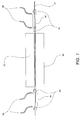
- Blade rollers 54 positioned as shown in Figures 7 and 8, maintain the horizontal position and stability of blade 22 during operation of saw 20; they are typically made of steel and provide back support to blade 22 as the workpiece is being pushed into and though blade 22, thereby preventing horizontal deflection of blade 22.
- Figures 9 and 10 show feed conveyor 56, which supports and feeds a workpiece into saw 20, and back conveyor 58 which supports and takes up a finished workpiece after slicing (NJR Industries, Mobile, Alabama). These conveyors are made with ruff grip top belt material to prevent slippage during operation. Conveyor drives 60 operate movement and speed of conveyors 56 and 58, and must be synchronized with the speed of pinch rollers 30, 31, 32, and 33 so that a workpiece may be fed through saw 20 at a steady, uniform rate. The edge of a slab or workpiece is lined up against workpiece guide rollers 62 on top of feed conveyor 56 to insure that the longitudinal axis of the workpiece remains substantially perpendicular to the direction of travel of blade 22 during the slicing operation.
- Figure 10 shows the position of a slab of polymeric material during the slicing operation.
- the height of the top surfaces of conveyors 56 and 58 are adjusted so as to align with the tops of lower rollers 32 and 33.
- This vertical position is set at some point below cutting level 64 on blade 22; level 64 corresponds to the lower vertical level of the cutting portion of blade 22.
- a typical distance between level 64 and the top level of alignment of rollers 32 and 33 and the top surfaces of conveyors 56 and 58 is about 1/8 inches.
- the speed of conveyors 56 and 58 and rollers 30, 31, 32, and 33 is then synchronized to provide for uniform stable feed of the slab or workpiece through saw 20.
- the slab is then laid flat on the top surface of conveyor 56, and the edge of the slab is positioned up against workpiece guide rollers 62. Rollers 62 are positioned along one edge of conveyor 56 so that the longitudinal axis of the slab may be positioned substantially perpendicular to the direction of travel of blade 22 as the slab is fed into saw 20.
- the slab is then fed forward into pinch rollers 30, 31, 32, and 33, which through pressurized contact hold the slab very stable and substantially parallel to blade 22 as the slab is fed into and passed through blade 22.
- coolant from nozzles 52 is sprayed onto the cutting area to cool, clean, and lubricate blade 22 and the workpiece.
- Blade guides 42 stabilize the vertical position and blade rollers 54 stabilize the horizontal position of blade 22 as it passes through the workpiece.
- the sliced slab then passes through the back of saw 20 onto back conveyor 58 which transfers the sliced slab away from saw 20.
- the main body of the previously sliced slab may then be run through saw 20 over again to produce another finished sheet, until the slab has been exhausted.
Landscapes
- Engineering & Computer Science (AREA)
- Mechanical Engineering (AREA)
- Life Sciences & Earth Sciences (AREA)
- Forests & Forestry (AREA)
- Processing Of Stones Or Stones Resemblance Materials (AREA)
- Details Of Cutting Devices (AREA)
Applications Claiming Priority (2)
| Application Number | Priority Date | Filing Date | Title |
|---|---|---|---|
| US65801 | 1998-04-23 | ||
| US09/065,801 US6196104B1 (en) | 1998-04-23 | 1998-04-23 | Apparatus for producing sheets of solid surfacing |
Publications (1)
| Publication Number | Publication Date |
|---|---|
| EP0958877A2 true EP0958877A2 (de) | 1999-11-24 |
Family
ID=22065206
Family Applications (1)
| Application Number | Title | Priority Date | Filing Date |
|---|---|---|---|
| EP99103887A Withdrawn EP0958877A2 (de) | 1998-04-23 | 1999-03-01 | Plattenschneidmaschine zum Abtrennen einer Platte,die Polymerteilchen enthält mit einer Abmessung grösser als die Dicke der Platte |
Country Status (7)
| Country | Link |
|---|---|
| US (1) | US6196104B1 (de) |
| EP (1) | EP0958877A2 (de) |
| JP (1) | JPH11347990A (de) |
| KR (1) | KR19990083452A (de) |
| CN (1) | CN1232739A (de) |
| AU (1) | AU720717B2 (de) |
| CA (1) | CA2265101A1 (de) |
Cited By (4)
| Publication number | Priority date | Publication date | Assignee | Title |
|---|---|---|---|---|
| FR3058346A1 (fr) * | 2016-11-10 | 2018-05-11 | Groupe Meyer-France | Installation de decoupe d'une piece en materiau metallique ou composite |
| AT522870A1 (de) * | 2019-05-24 | 2021-02-15 | Wintersteiger Ag | Dünnschnitt-Bandsäge |
| WO2024008608A1 (en) * | 2022-07-05 | 2024-01-11 | Philip Morris Products S.A. | Method for operating a continuous blade |
| KR102917190B1 (ko) * | 2024-07-17 | 2026-01-27 | (주)대한솔루션 | 폴리우레탄 폼 시트의 커팅 장치 |
Families Citing this family (8)
| Publication number | Priority date | Publication date | Assignee | Title |
|---|---|---|---|---|
| AU2002355296A1 (en) * | 2001-07-25 | 2003-02-17 | Lhr Technologies | Processor-controlled carving and multi-purpose shaping device |
| EP1350773A3 (de) * | 2002-04-03 | 2006-03-22 | Diatexs Co., Ltd. | Thermoplastische Harz für Zementbewehrung und bewehrte Zementmischungen |
| CA2687619C (en) * | 2009-12-08 | 2011-11-15 | Norwood Industries Inc. | Integrated blade lubrication controller |
| CN104117996A (zh) * | 2014-02-22 | 2014-10-29 | 钱中山 | 一种模压超高分子量聚乙烯板材生产方法 |
| US10882126B2 (en) * | 2017-01-13 | 2021-01-05 | ESCO Group, Inc. | Take-up and payoff system for vertical profiling cutting saw (VPX) |
| CN110126003B (zh) * | 2019-06-19 | 2021-02-12 | 贵州金域医学检验中心有限公司 | 一种滑式冷冻组织切片器 |
| CN111975109B (zh) * | 2020-07-05 | 2022-04-26 | 黄朋飞 | 一种高速数控锯床控制系统及方法 |
| CN115255498A (zh) * | 2022-06-03 | 2022-11-01 | 浙江伟业锯床有限公司 | 一种对工件连续锯断的锯床 |
Citations (6)
| Publication number | Priority date | Publication date | Assignee | Title |
|---|---|---|---|---|
| US3371383A (en) | 1965-09-28 | 1968-03-05 | Swedlow Inc | Continuous casting apparatus |
| US3376371A (en) | 1965-09-28 | 1968-04-02 | Swedlow Inc | Continuous casting process |
| US4433070A (en) | 1980-05-05 | 1984-02-21 | Ross Gilbert B | Cultured onyx products and methods therefor |
| US4446177A (en) | 1982-03-12 | 1984-05-01 | Munoz George L | Reinforced plastic product |
| US5242968A (en) | 1990-08-27 | 1993-09-07 | Aristech Chemical Corporation | Acrylic-filled thermoformable acrylic sheet |
| US5244941A (en) | 1989-11-02 | 1993-09-14 | Ralph Wilson Plastics Company | Artificial stone compositions, process of producing the same, and apparatus employed in the production thereof |
Family Cites Families (49)
| Publication number | Priority date | Publication date | Assignee | Title |
|---|---|---|---|---|
| US1987551A (en) | 1931-07-31 | 1935-01-08 | Edwall Axel Laurentz | Band saw |
| US2670771A (en) | 1949-08-30 | 1954-03-02 | Armstrong Cork Co | Automatic splitting machine |
| US2685311A (en) | 1951-11-16 | 1954-08-03 | Ernest R Ferrari | Method for splitting or resawing insulating board |
| US2862231A (en) | 1955-03-10 | 1958-12-02 | Lonza Werke Elektrochemisch Fa | Method and apparatus for dividing thermoplastic bodies |
| US3025741A (en) | 1957-01-24 | 1962-03-20 | Dayco Corp | Apparatus for cutting sheet material |
| US2958352A (en) | 1958-01-20 | 1960-11-01 | Pacific Wood Products Co | Method for producing decorative wood panels |
| US2963054A (en) * | 1958-04-09 | 1960-12-06 | Yates American Machine Co | Tension adjusting mechanism for band saws |
| US3092155A (en) | 1960-05-13 | 1963-06-04 | Jr Aubrey A Fowler | Horizontal band saw |
| US3104576A (en) * | 1960-11-21 | 1963-09-24 | Continental Machines | Combination saw guide and coolant applicator for band sawing machines |
| US3045520A (en) | 1961-10-02 | 1962-07-24 | Haruyama Ichizo | Apparatus for cutting chemical tows |
| US3263537A (en) * | 1964-04-13 | 1966-08-02 | Falls Engineering & Machine Co | Endless band knife apparatus |
| US3374812A (en) | 1964-06-26 | 1968-03-26 | Charles E. Mcmanama | Positioning and retaining device system for logs in a high capacity sawmill employing a horizontal traversing bandsaw adjustably mounted over the log being sawed |
| US3396615A (en) | 1966-01-21 | 1968-08-13 | Falls Engineering & Machine Co | Ribbon guide take-up for splitting machinery |
| GB1260469A (en) | 1968-04-03 | 1972-01-19 | English Clays Lovering Pochin | Artificial roadstones, and bituminous compositions containing the same for use in roads, airfield runways and the like |
| IL32158A (en) | 1968-12-10 | 1972-11-28 | Medil Spa | Process for the manufacture of articles of artificial stone |
| US3736820A (en) | 1971-12-22 | 1973-06-05 | Krauss & Reichert Maschf | Slicing machine for expanded plastics and similar materials |
| SE361844B (de) | 1972-09-20 | 1973-11-19 | R T Wirstroem | |
| NO744653L (de) | 1974-01-03 | 1975-07-28 | Eiselt Guenter | |
| DE2434050C3 (de) | 1974-07-16 | 1978-04-27 | Albrecht Baeumer Kg Spezialmaschinenfabrik, 5905 Freudenberg | Zweiseitig schneidende Schaumstoffspaltmaschine |
| US3972254A (en) | 1975-01-20 | 1976-08-03 | Kemos Incorporated | Cutting mechanism and method for cutting or slicing strips fed thereto |
| US4085246A (en) | 1975-06-18 | 1978-04-18 | E. I. Du Pont De Nemours And Company | Simulated granite and its preparation |
| US3954037A (en) * | 1975-07-09 | 1976-05-04 | Emilio Retana Rodriguez | Linear motor band saw |
| DE2543990C3 (de) | 1975-10-02 | 1980-10-30 | Krauss U. Reichert Gmbh + Co Kg Spezialmaschinenfabrik, 7012 Fellbach | Horizontalspaltmaschine |
| GB1571420A (en) | 1977-05-04 | 1980-07-16 | Fibreglass Ltd | Cutting of material |
| US4111085A (en) | 1977-05-10 | 1978-09-05 | Lockheed Corporation | Compound curvature cutting machine |
| CA1119811A (en) * | 1980-01-25 | 1982-03-16 | Cominco Ltd. | Cutting apparatus for semi-conductor materials |
| US4441396A (en) | 1980-09-03 | 1984-04-10 | Societe Mercier Freres | Slitting machine, more particularly for hides and leather, unwoven textile products, rubber products, plastics in plates or rolls |
| DE3040694A1 (de) | 1980-10-29 | 1982-07-29 | Wezel GmbH & Co KG, 3560 Biedenkopf | Verfahren und vorrichtung zum herstellen von kalottenfoermigen ausschnitten waermedaemmender waende aus kunststoffschaum |
| DE3174204D1 (en) | 1980-11-06 | 1986-04-30 | Paul Elsey | Portable power saw mill |
| US4501181A (en) * | 1982-03-19 | 1985-02-26 | Armstrong-Blum Manufacturing Co. | Method for delivering coolant to a band saw, and structure therefor |
| FR2524843A1 (fr) | 1982-04-07 | 1983-10-14 | Michelin & Cie | Procede et dispositif permettant d'obtenir des bandes a partir d'un materiau, notamment un caoutchouc; bandes ainsi obtenues |
| FR2528353B1 (fr) | 1982-06-10 | 1985-06-21 | Michelin & Cie | Procede et dispositif permettant d'obtenir des feuilles a partir d'un materiau souple, notamment d'un coagulum de latex; feuilles ainsi obtenues |
| US4478120A (en) | 1982-11-12 | 1984-10-23 | Daito Seiki Company Limited | Metal-sawing machine |
| US4484417A (en) * | 1982-11-22 | 1984-11-27 | W. J. Savage Company | Sawing apparatus |
| FR2536698A1 (fr) | 1982-11-29 | 1984-06-01 | Michelin & Cie | Procede et dispositif permettant d'obtenir des bandes a partir d'un materiau, notamment d'un coagulum de latex; bandes ainsi obtenues |
| FR2537913A1 (fr) | 1982-12-15 | 1984-06-22 | Rocamat Sa | Dispositif pour la coupe de blocs de granit, marbres, pierres et autres produits analogues |
| GB2137550B (en) * | 1983-03-31 | 1986-12-31 | Alpine Plastic Machinery Limit | Web cutting |
| US4567739A (en) | 1984-03-13 | 1986-02-04 | Paolo Mascetti | Platform for introducing sheet materials, particularly in leather splitting machines and the like |
| FR2578188B1 (fr) | 1985-03-04 | 1987-05-07 | Tilex France Sarl | Procede de fabrication de plaques de revetement agglomere |
| JPS63260792A (ja) | 1987-04-20 | 1988-10-27 | 株式会社 桜エンジニアリング | 自動漉割機 |
| US4885967A (en) | 1988-08-25 | 1989-12-12 | J. Gibson Mcilvain Company | Laser alignment device for sawmills |
| US5043377A (en) | 1988-10-07 | 1991-08-27 | Nippon Shokubai Kagaku Kogyo Company, Ltd. | Granite-like artificial stone |
| FR2637826B1 (fr) * | 1988-10-17 | 1990-12-14 | Missler Patrick | Machine a scier a ruban horizontal |
| SE9100881L (sv) | 1991-03-25 | 1992-09-26 | Josef Jindra | Minisaagverket |
| AU2447192A (en) * | 1991-11-12 | 1993-06-15 | Gary D. Morgan | Horizontal band resaw |
| US5213022A (en) | 1992-07-01 | 1993-05-25 | Elgan Douglas L | Multi-directional portable band sawmill for lumber and firewood |
| DE4309134C2 (de) * | 1993-03-22 | 1999-03-04 | Wilfried Wahl | Verfahren zur Schmierung und Kühlung von Schneiden und/oder Werkstücken bei zerspanenden Arbeitsprozessen |
| JPH083880A (ja) | 1994-06-17 | 1996-01-09 | Kanebo Ltd | パール調バフタイプの人工皮革 |
| JPH09302009A (ja) | 1996-05-09 | 1997-11-25 | Takeda Chem Ind Ltd | 不飽和ポリエステル樹脂組成物 |
-
1998
- 1998-04-23 US US09/065,801 patent/US6196104B1/en not_active Expired - Fee Related
-
1999
- 1999-03-01 EP EP99103887A patent/EP0958877A2/de not_active Withdrawn
- 1999-03-04 AU AU18583/99A patent/AU720717B2/en not_active Ceased
- 1999-03-08 CA CA002265101A patent/CA2265101A1/en not_active Abandoned
- 1999-04-01 JP JP11094778A patent/JPH11347990A/ja active Pending
- 1999-04-06 CN CN99104922A patent/CN1232739A/zh active Pending
- 1999-04-23 KR KR1019990014707A patent/KR19990083452A/ko not_active Ceased
Patent Citations (9)
| Publication number | Priority date | Publication date | Assignee | Title |
|---|---|---|---|---|
| US3371383A (en) | 1965-09-28 | 1968-03-05 | Swedlow Inc | Continuous casting apparatus |
| US3376371A (en) | 1965-09-28 | 1968-04-02 | Swedlow Inc | Continuous casting process |
| US4433070A (en) | 1980-05-05 | 1984-02-21 | Ross Gilbert B | Cultured onyx products and methods therefor |
| US4433070B1 (de) | 1980-05-05 | 1987-02-10 | ||
| US4433070B2 (en) | 1980-05-05 | 1991-07-02 | Cultured onyx products and methods therefor | |
| US4433070B3 (en) | 1980-05-05 | 1998-07-21 | Spectrum 21 Licensing Corp | Cultured onyx products and methods therefor |
| US4446177A (en) | 1982-03-12 | 1984-05-01 | Munoz George L | Reinforced plastic product |
| US5244941A (en) | 1989-11-02 | 1993-09-14 | Ralph Wilson Plastics Company | Artificial stone compositions, process of producing the same, and apparatus employed in the production thereof |
| US5242968A (en) | 1990-08-27 | 1993-09-07 | Aristech Chemical Corporation | Acrylic-filled thermoformable acrylic sheet |
Cited By (6)
| Publication number | Priority date | Publication date | Assignee | Title |
|---|---|---|---|---|
| FR3058346A1 (fr) * | 2016-11-10 | 2018-05-11 | Groupe Meyer-France | Installation de decoupe d'une piece en materiau metallique ou composite |
| WO2018087458A1 (fr) * | 2016-11-10 | 2018-05-17 | Groupe Meyer-France | Installation de decoupe d'une piece en materiau metallique ou composite |
| AT522870A1 (de) * | 2019-05-24 | 2021-02-15 | Wintersteiger Ag | Dünnschnitt-Bandsäge |
| AT522870B1 (de) * | 2019-05-24 | 2021-12-15 | Wintersteiger Ag | Dünnschnitt-Bandsäge |
| WO2024008608A1 (en) * | 2022-07-05 | 2024-01-11 | Philip Morris Products S.A. | Method for operating a continuous blade |
| KR102917190B1 (ko) * | 2024-07-17 | 2026-01-27 | (주)대한솔루션 | 폴리우레탄 폼 시트의 커팅 장치 |
Also Published As
| Publication number | Publication date |
|---|---|
| KR19990083452A (ko) | 1999-11-25 |
| AU720717B2 (en) | 2000-06-08 |
| AU1858399A (en) | 1999-11-04 |
| US6196104B1 (en) | 2001-03-06 |
| JPH11347990A (ja) | 1999-12-21 |
| CN1232739A (zh) | 1999-10-27 |
| CA2265101A1 (en) | 1999-10-23 |
Similar Documents
| Publication | Publication Date | Title |
|---|---|---|
| US6196104B1 (en) | Apparatus for producing sheets of solid surfacing | |
| US5496206A (en) | Building block face enhancement apparatus | |
| US3303245A (en) | Process for production of tile products | |
| CA1147542A (en) | Edge finishing machine | |
| CN104526494B (zh) | 一种石板磨边机 | |
| AU725887B2 (en) | Method for producing sheets of solid surfacing and solid surfacing produced thereby | |
| US7909028B2 (en) | Inlaid stone composite | |
| US6997175B2 (en) | Portable apparatus for working, shaping and polishing stone and other hard materials | |
| KR100267793B1 (ko) | 패널(panel) 또는 스트립(strip)의 다듬질 장치 | |
| CN216298897U (zh) | 石材岩板磨边机 | |
| WO2014061050A1 (en) | Automatic sawing machine for cutting stones and materials of irregular shape and different sizes | |
| HK1023087A (en) | Apparatus for slicing off sheets containing polymeric particles with a dimension greater than thickness of the sheet | |
| HK1022465A (en) | Method for producing sheets of solid surface and sheets produced thereby | |
| RU2169071C2 (ru) | Устройство для механической обработки заготовки и способ механической обработки | |
| CN112643498B (zh) | 一种管材加工用打磨装置 | |
| EP0839608B1 (de) | Polier- und Glättmaschine für Platten, Kacheln und dergleichen | |
| CN2355860Y (zh) | 瓷砖切割机 | |
| CN1059857C (zh) | 数控超薄型天然复合石材切割机 | |
| CN2381459Y (zh) | 新型数控石材曲面加工机床 | |
| US5865668A (en) | Shaper head for making mouldings | |
| US1850432A (en) | Machine for finishing edges of strips of material | |
| CN211807036U (zh) | 一种人造石装饰石料的平面切割成型装置 | |
| CN110948315A (zh) | 一种木制品打磨装置 | |
| CN2233824Y (zh) | 石材角板超宽平面板一次成型切割机 | |
| CN220279912U (zh) | 高剪切精度闸式剪板机 |
Legal Events
| Date | Code | Title | Description |
|---|---|---|---|
| PUAI | Public reference made under article 153(3) epc to a published international application that has entered the european phase |
Free format text: ORIGINAL CODE: 0009012 |
|
| 17P | Request for examination filed |
Effective date: 19990301 |
|
| AK | Designated contracting states |
Kind code of ref document: A2 Designated state(s): AT BE CH CY DE DK ES FI FR GB GR IE IT LI LU MC NL PT SE |
|
| AX | Request for extension of the european patent |
Free format text: AL;LT;LV;MK;RO;SI |
|
| STAA | Information on the status of an ep patent application or granted ep patent |
Free format text: STATUS: THE APPLICATION IS DEEMED TO BE WITHDRAWN |
|
| 18D | Application deemed to be withdrawn |
Effective date: 20011002 |
|
| REG | Reference to a national code |
Ref country code: HK Ref legal event code: WD Ref document number: 1023087 Country of ref document: HK |