EP0959194A2 - Dispositif de pliage - Google Patents
Dispositif de pliage Download PDFInfo
- Publication number
- EP0959194A2 EP0959194A2 EP99108756A EP99108756A EP0959194A2 EP 0959194 A2 EP0959194 A2 EP 0959194A2 EP 99108756 A EP99108756 A EP 99108756A EP 99108756 A EP99108756 A EP 99108756A EP 0959194 A2 EP0959194 A2 EP 0959194A2
- Authority
- EP
- European Patent Office
- Prior art keywords
- profile
- support frame
- support
- actuating lever
- sword
- Prior art date
- Legal status (The legal status is an assumption and is not a legal conclusion. Google has not performed a legal analysis and makes no representation as to the accuracy of the status listed.)
- Withdrawn
Links
- 238000005452 bending Methods 0.000 claims description 25
- 238000005253 cladding Methods 0.000 claims description 20
- 238000000034 method Methods 0.000 claims description 6
- 238000010276 construction Methods 0.000 description 2
- 230000000149 penetrating effect Effects 0.000 description 1
Images



Classifications
-
- E—FIXED CONSTRUCTIONS
- E04—BUILDING
- E04D—ROOF COVERINGS; SKY-LIGHTS; GUTTERS; ROOF-WORKING TOOLS
- E04D13/00—Special arrangements or devices in connection with roof coverings; Protection against birds; Roof drainage ; Sky-lights
- E04D13/15—Trimming strips; Edge strips; Fascias; Expansion joints for roofs
-
- E—FIXED CONSTRUCTIONS
- E04—BUILDING
- E04D—ROOF COVERINGS; SKY-LIGHTS; GUTTERS; ROOF-WORKING TOOLS
- E04D15/00—Apparatus or tools for roof working
- E04D15/04—Apparatus or tools for roof working for roof coverings comprising slabs, sheets or flexible material
Definitions
- the invention relates to a device for bending profiles, in particular for turning a roof trim panel profile molded retaining webs.
- EP 0 184 639 B1 discloses a roof edge covering in which the Roof covering by means of a clamping piece, which with one of the Cladding profile protruding retaining bridge can be locked to the respective Adjust conditions, is pressed against the connecting web, so that ensures a secure locking of the roof covering in the cladding profile is, but the material and assembly effort is considerable.
- the one Receiving pocket provided clamping piece is namely by hand on the holding bridge different pressure forces have to be accepted, is also an assembly of the known with a two-part cladding profile equipped roof edge cladding can not be done in a short time.
- the object of the invention is therefore to provide a bending device by means of which is possible in a simple manner and in a short time to a web of a profile deform that this e.g. is pressed against a roof covering, so that whose locking a one-piece profile can be used.
- the one for that required construction effort should be kept low, including the bending device thus to be produced in an economical manner, but above all to be achieved that the bending device is easy to handle and that a smooth Deformation of the web is to be carried out so that it is always uniform Contact pressure acts on the roof cover.
- damage to the the profile to be edited can be reliably avoided.
- the device for bending profiles in particular for bending a retaining web molded onto a roof edge cladding profile characterized by a support frame on which the profile to be machined a bending process is supported, and one on the part of the profile to be bent Sword acting on one in the direction of the profile parallel to one this extending axis limited pivotable on the support frame articulated operating lever is attached.
- the height adjustment of the preferably designed as a plate support the support frame with perpendicular to the axis can be provided to the profile to be machined locking grooves in which the support e.g. by means of bolts attached to this in different Distances to the sword can be locked, and the locking grooves preferably recesses running opposite to the direction of advance of the profile Recording the bolts are provided.
- the support frame as a rectangular ring or as a plate train and this on the face facing the sword with a or a plurality of contact plates, preferably arranged in both edge areas Support of the profile to be machined and on the support opposite side with one or more contact rollers, between the and the support the profile to be machined is supported.
- the adjustment path of the first actuating lever can be easily done by a be arranged concentrically to the hinge pin ring segment that has a guide groove, preferably provided with latching recesses, into which the operating lever e.g. engages with an adjusting screw.
- the ring segment can in this case by means of a pin engaging in the guide groove or the like the second operating lever should be held, the second should Operating lever cranked and the two operating levers in parallel be mutually pivotable planes.
- a bending device is designed according to the invention, it is very simple way possible profiles, especially one at a Roof edge cladding profile provided holding web to deform such that by the deformed part e.g. a roof pad is pressed against a counter bearing and thus a secure mounting of the roof cover is given.
- the one for that required construction effort of the bending device is very low, so that this is economical to produce, but most of all it is advantageous that the Deformation of the part of the profile to be bent and thus the contact pressure adjusted and adapted to the respective circumstances without difficulty can be.
- the profile to be machined on the Support frame of the bending device is applied and for that acting on it Sword a counter bearing is provided, are undesirable deformations of the Profiles almost impossible. With simple handling is therefore short Time a roof covering in a roof trim profile without it requires special expertise, by turning a footbridge securely to clamp.
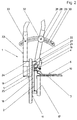
- each designated 1 Bending device is used to deform a profile, in particular for bending a retaining web 4 of a roof edge cladding profile 2, which by means of a Dock 3 is attached to a building 10 and consists essentially of a support frame 11 for supporting the roof edge trim profile 2 during of the bending process and a sword 13, which on the holding web 4 of Roof edge cladding profile 2 acts.
- the support frame 11 is here as right-angled ring consisting of an upper part 12, a lower part 13 and two cheeks 14 and 15 assembled, which accommodate a support 17.
- abutment rollers 19 are provided so that the cladding profile 21, like this can be seen in particular from Figures 2 and 3, between the support 17 and the abutment rollers 19 is supported when abutting the abutment plates 18.
- the sword 16 is on a first actuating lever 22 by means of a screw 27 attached to a hinge pin 21 held in a fork piece 20 is pivotally mounted. There is also a second one on the hinge pin 21 arranged on the opposite side of the support frame 11 Actuating lever 23 also by means of these penetrating plates 24 pivoted, which is an insertable into the support frame 11 plate-shaped Counter bearing 26 carries. The counter bearing 26 is screwed to an angle piece 25, which is firmly connected to the second operating lever 23. The cladding profile 2 is thus through the entire length of the sword 16 acting on it the bearing plates 18 and the counter bearing 26 supported, deformations during a bending process is therefore almost impossible.
- the roof covering 6 is in insert this and the bending device 1 is in the manner shown Set up cladding profile 2.
- the actuating levers 22 and 23 to adjust so that the cranked on the second Actuating lever 23 attached counter bearing 26 is aligned with the support plates 18, and the sword 16 is by means of the first operating lever 22 against the Retaining web 4 of the cladding profile 2, which has a deformable area 5, too press so that it is deformed until it touches the roof cover 6.
- the roof covering 6 is clamped in the cladding profile 2.
- the bending device 1 is after the two Operating levers 22 and 23 are returned to the starting position, approximately by the Width of the support frame 11 to move in the direction of the cladding profile 2 then deform another piece of the retaining web 4 in the same way.
- the adjustment of the sword 16 is limited.
- the ring segment 28 has a guide groove 29 and on the Actuating levers 22 and 23 have bolts 31 and 33 attached to them Engage the guide groove 29.
- the end region is the guide groove 29 further with latching recesses 30 equipped, into which the bolt 31 can be inserted and by means of an adjusting screw 33 to be able to easily adjust the adjustment path for certain profiles. Since the bolts 33 attached to the second actuating lever 23 guide groove 29 reaches, the ring segment 28 can thus on the first actuating lever 22 locked and its adjustment path can also be set as desired.
- FIG. 4 shows, in the cheeks 14 and 15, the same-directed locking grooves 34 incorporated and on the support 17 bolts 36 are provided which in the Locking grooves 34 are adjustable in height and can be snapped into recesses 35.
- the locking grooves 34 each have three Have cutouts 35, thus three differently sized Cladding profiles are clamped and processed in the support frame 11.
- the Recesses 35 run in the feed direction of the cladding profile 11, so that the support 17 by moving the cladding profile 11 not from the Support frame 11 is released.
Landscapes
- Engineering & Computer Science (AREA)
- Architecture (AREA)
- Civil Engineering (AREA)
- Structural Engineering (AREA)
- Bending Of Plates, Rods, And Pipes (AREA)
- Roof Covering Using Slabs Or Stiff Sheets (AREA)
Applications Claiming Priority (2)
| Application Number | Priority Date | Filing Date | Title |
|---|---|---|---|
| DE19822389 | 1998-05-19 | ||
| DE1998122389 DE19822389A1 (de) | 1998-05-19 | 1998-05-19 | Biegevorrichtung |
Publications (2)
| Publication Number | Publication Date |
|---|---|
| EP0959194A2 true EP0959194A2 (fr) | 1999-11-24 |
| EP0959194A3 EP0959194A3 (fr) | 2001-01-17 |
Family
ID=7868255
Family Applications (1)
| Application Number | Title | Priority Date | Filing Date |
|---|---|---|---|
| EP99108756A Withdrawn EP0959194A3 (fr) | 1998-05-19 | 1999-05-03 | Dispositif de pliage |
Country Status (2)
| Country | Link |
|---|---|
| EP (1) | EP0959194A3 (fr) |
| DE (1) | DE19822389A1 (fr) |
Citations (1)
| Publication number | Priority date | Publication date | Assignee | Title |
|---|---|---|---|---|
| EP0184639A2 (fr) | 1984-12-14 | 1986-06-18 | International Business Machines Corporation | Système de test pour circuits d'interfaces de claviers |
Family Cites Families (4)
| Publication number | Priority date | Publication date | Assignee | Title |
|---|---|---|---|---|
| US3166961A (en) * | 1963-09-13 | 1965-01-26 | Sr Joseph Edward Chaplin | Sheet metal roofing fastener bender |
| US4192115A (en) * | 1975-08-12 | 1980-03-11 | Ryohei Yamamoto | Elongated shingle assembly |
| US4318211A (en) * | 1980-06-26 | 1982-03-09 | James Hoskinson | Crimping tool for automobile door panels |
| DE29807149U1 (de) * | 1998-04-21 | 1998-09-03 | Flaschner Gemeinschaft Ostalb GmbH, 73431 Aalen | Vorrichtung zum Schließen einer Blende an ortsfesten Bauelementen |
-
1998
- 1998-05-19 DE DE1998122389 patent/DE19822389A1/de not_active Withdrawn
-
1999
- 1999-05-03 EP EP99108756A patent/EP0959194A3/fr not_active Withdrawn
Patent Citations (1)
| Publication number | Priority date | Publication date | Assignee | Title |
|---|---|---|---|---|
| EP0184639A2 (fr) | 1984-12-14 | 1986-06-18 | International Business Machines Corporation | Système de test pour circuits d'interfaces de claviers |
Also Published As
| Publication number | Publication date |
|---|---|
| EP0959194A3 (fr) | 2001-01-17 |
| DE19822389A1 (de) | 1999-11-25 |
Similar Documents
| Publication | Publication Date | Title |
|---|---|---|
| DE102011050520B4 (de) | Fliesenschneider | |
| DE2714082C2 (de) | Scharnier | |
| DE4335387C2 (de) | Schwenktüre für Duschkabine | |
| DE3606525C2 (de) | Führungseinrichtung für Elektrohandwerkzeuge | |
| EP0122335B1 (fr) | Barre profilée | |
| DE20119997U1 (de) | Befestigungsvorrichtung | |
| DE4102941C2 (de) | Vorrichtung zum Höhenverlagern einer Fahrzeugfensterscheibe | |
| EP0144926A2 (fr) | Dispositif pour la fixation de caissons aux murs et/ou aux plafonds | |
| EP0445363A1 (fr) | Dispositif de fraisage ou perçage | |
| DE19822389A1 (de) | Biegevorrichtung | |
| DE2613673A1 (de) | Spannvorrichtung | |
| DE3637985C2 (de) | Biegestanze | |
| DE3828482C2 (de) | Stoss- oder Ziehwerkzeug | |
| EP1630312B1 (fr) | Connecteur de murs | |
| DE2609670A1 (de) | Geradfuehrung fuer ein mess- und/oder anreissgeraet | |
| EP4349530B1 (fr) | Dispositif de fixation pour une pièce à usiner | |
| DE3443140C2 (fr) | ||
| DE3307287A1 (de) | Werkstueckaufnahme fuer eine holzbearbeitungsmaschine mit einem quer zur vorschubrichtung angeordneten werkstueckanschlag | |
| DE102022125475B4 (de) | Wasserstrahlschneideverfahren | |
| DE3941613A1 (de) | Befestigungsvorrichtung | |
| AT397532B (de) | Spannzwinge | |
| EP1358978B1 (fr) | Dispositif pour poinçonner des plinthes, en particulier des plinthes avec un coeur | |
| DE2756627B2 (de) | Spannvorrichtung | |
| DE102022125476A1 (de) | Befestigungsvorrichtung für ein Werkstück | |
| DE3511957C2 (fr) |
Legal Events
| Date | Code | Title | Description |
|---|---|---|---|
| PUAI | Public reference made under article 153(3) epc to a published international application that has entered the european phase |
Free format text: ORIGINAL CODE: 0009012 |
|
| AK | Designated contracting states |
Kind code of ref document: A2 Designated state(s): AT BE CH CY DE DK ES FI FR GB GR IE IT LI LU MC NL PT SE |
|
| AX | Request for extension of the european patent |
Free format text: AL;LT;LV;MK;RO;SI |
|
| RAP1 | Party data changed (applicant data changed or rights of an application transferred) |
Owner name: CORUS ALUMINIUM PROFILTECHNIK GMBH |
|
| PUAL | Search report despatched |
Free format text: ORIGINAL CODE: 0009013 |
|
| AK | Designated contracting states |
Kind code of ref document: A3 Designated state(s): AT BE CH CY DE DK ES FI FR GB GR IE IT LI LU MC NL PT SE |
|
| AX | Request for extension of the european patent |
Free format text: AL;LT;LV;MK;RO;SI |
|
| AKX | Designation fees paid | ||
| REG | Reference to a national code |
Ref country code: DE Ref legal event code: 8566 |
|
| STAA | Information on the status of an ep patent application or granted ep patent |
Free format text: STATUS: THE APPLICATION IS DEEMED TO BE WITHDRAWN |
|
| 18D | Application deemed to be withdrawn |
Effective date: 20010718 |