EP0959471B1 - Kassette für Informationsaufzeichnungsträger - Google Patents
Kassette für Informationsaufzeichnungsträger Download PDFInfo
- Publication number
- EP0959471B1 EP0959471B1 EP99303953A EP99303953A EP0959471B1 EP 0959471 B1 EP0959471 B1 EP 0959471B1 EP 99303953 A EP99303953 A EP 99303953A EP 99303953 A EP99303953 A EP 99303953A EP 0959471 B1 EP0959471 B1 EP 0959471B1
- Authority
- EP
- European Patent Office
- Prior art keywords
- opening cover
- cartridge case
- cartridge
- opening
- recording medium
- Prior art date
- Legal status (The legal status is an assumption and is not a legal conclusion. Google has not performed a legal analysis and makes no representation as to the accuracy of the status listed.)
- Expired - Lifetime
Links
Images

Classifications
-
- G—PHYSICS
- G11—INFORMATION STORAGE
- G11B—INFORMATION STORAGE BASED ON RELATIVE MOVEMENT BETWEEN RECORD CARRIER AND TRANSDUCER
- G11B23/00—Record carriers not specific to the method of recording or reproducing; Accessories, e.g. containers, specially adapted for co-operation with the recording or reproducing apparatus ; Intermediate mediums; Apparatus or processes specially adapted for their manufacture
- G11B23/02—Containers; Storing means both adapted to cooperate with the recording or reproducing means
- G11B23/03—Containers for flat record carriers
- G11B23/0301—Details
- G11B23/0302—Auxiliary features
-
- G—PHYSICS
- G11—INFORMATION STORAGE
- G11B—INFORMATION STORAGE BASED ON RELATIVE MOVEMENT BETWEEN RECORD CARRIER AND TRANSDUCER
- G11B23/00—Record carriers not specific to the method of recording or reproducing; Accessories, e.g. containers, specially adapted for co-operation with the recording or reproducing apparatus ; Intermediate mediums; Apparatus or processes specially adapted for their manufacture
- G11B23/02—Containers; Storing means both adapted to cooperate with the recording or reproducing means
- G11B23/03—Containers for flat record carriers
- G11B23/0301—Details
- G11B23/0306—Means for locking the record carriers
-
- G—PHYSICS
- G11—INFORMATION STORAGE
- G11B—INFORMATION STORAGE BASED ON RELATIVE MOVEMENT BETWEEN RECORD CARRIER AND TRANSDUCER
- G11B23/00—Record carriers not specific to the method of recording or reproducing; Accessories, e.g. containers, specially adapted for co-operation with the recording or reproducing apparatus ; Intermediate mediums; Apparatus or processes specially adapted for their manufacture
- G11B23/02—Containers; Storing means both adapted to cooperate with the recording or reproducing means
- G11B23/03—Containers for flat record carriers
- G11B23/0301—Details
- G11B23/0308—Shutters
-
- G—PHYSICS
- G11—INFORMATION STORAGE
- G11B—INFORMATION STORAGE BASED ON RELATIVE MOVEMENT BETWEEN RECORD CARRIER AND TRANSDUCER
- G11B23/00—Record carriers not specific to the method of recording or reproducing; Accessories, e.g. containers, specially adapted for co-operation with the recording or reproducing apparatus ; Intermediate mediums; Apparatus or processes specially adapted for their manufacture
- G11B23/02—Containers; Storing means both adapted to cooperate with the recording or reproducing means
- G11B23/03—Containers for flat record carriers
- G11B23/0301—Details
- G11B23/0317—Containers with interchangeable record carriers
Definitions
- the present invention relates to a cartridge for accommodating and protecting an information recording medium such as an optical disc so that information is recordable/reproducible on/from the optical disc. More particularly, the present invention relates to a cartridge which has an information recording medium holding means that enables a user to replace the information recording medium without directly touching the same, and prevents the information recording medium from separating from the cartridge while the user replaces the same.
- a disc cartridge protects a disc such as an optical disc from dust, fingerprints, scratches, etc., so that information may be recorded/reproduced on/from the disc without an error.
- a cartridge includes a case which is generally made from a synthetic resin, and an opening cover which selectively opens/closes a disc entry opening of the case.
- a reference numeral 10 refers to a cartridge case, which has an upper shell and a lower shell that are coupled with each other to define a space therebetween.
- a disc d is accommodated in the space defined by the upper and lower shells.
- a spindle opening 10a and an extended opening 10b are formed in the upper and lower shells.
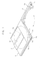
- a shutter 12 is slidably disposed on the cartridge case 10, to selectively open/close the spindle opening 10a and the extended opening 10b.
- the shutter 12 is automatically opened/closed in response to the inserting and withdrawing actions of the disc cartridge with respect to the optical recording/reproducing device.
- a plurality of sensing holes 10c, 10d, 10e, and 10f are formed in the cartridge case 10, corresponding to a plurality of sensing switches of the optical recording/reproducing device which are to be selectively inserted thereinto. Accordingly, the states of the disc d are detected.
- the sensing holes 10c, 10d, 10e, and 10f are divided into an A1 hole 10c for detecting whether or not the disc d has been withdrawn from the cartridge case 10, an A2 hole 10d for detecting whether the disc d is a single-sided or a double-sided, a spare hole 10e which is available for use for an additional function, and a protection hole 10f for preventing information from being recorded on the disc d.
- additional holes such as a position hole are formed in the cartridge case 10, albeit they are not shown in the drawings.
- an opening cover 14 is hinged to a rear side of the cartridge case 10 to permit the disc d to be inserted or withdrawn with respect to the cartridge case 10.
- a plurality of holes 14a are formed in the opening cover 14 to correspond to the sensing holes 10c, 10d, 10e, and 10f, respectively.
- a lock lever 14b is disposed on the opening cover 14 to be locked into a lock hole 10g of the cartridge case 10, and a protector arm as well as a protector rib (not shown) are integrally formed on the cartridge case 10 by injection molding.
- the protector arm is positioned in the protection hole 10f, and the rib is to be locked with the protector arm.
- the A1 hole 10c is closed by the protector rib. Then, if the disc d is withdrawn from the cartridge case 10, the rib is eliminated so that the Al hole 10c is opened. Accordingly, the sensing switch of the optical recording/reproducing device is inserted into the A1 hole 10c when the disc cartridge is inserted into the optical recording/reproducing device, so that it is determined that the disc d has been exchanged. As a result, the verification process on the disc d is carried out.
- the A2 hole 10d is excluded if the disc d accommodated in the cartridge case 10 is single-sided, or when the disc cartridge is one that does not allow the disc d to be exchanged.
- the shutter 12 of the cartridge case 10 is moved in a predetermined direction (upper left in Figure 1 ) by a shutter opening/closing device (not shown), and accordingly, the spindle opening 10a and the extended opening 10b of the cartridge case 10 are opened. Simultaneously, the turntable and the chucking clamper of the optical recording/reproducing device are advanced through the spindle opening 10a so that the disc d is positioned and chucked.
- a position pin (not shown) of the optical recording/reproducing device is inserted into the position hole so that the position of the disc cartridge with respect to the optical recording/reproducing device is determined.
- the sensing switches of the optical recording/reproducing device are selectively inserted into the sensing holes 10c, 10d, 10e, and 10f and their respective corresponding holes 14a of the opening cover 14, so that the states of the disc d are determined.
- the sensing switch corresponding with the A1 sensing hole 10c is not inserted into the A1 sensing hole 10c, then it is determined that the disc d has never been exchanged, so that information can be directly recorded on the disc d without the verification process.
- the corresponding sensing switch When the corresponding sensing switch is inserted into the A1 hole 10c, then it is determined that the disc d has been exchanged, so that the verification process is carried out and then the information is recorded on the disc d. Further, when the corresponding sensing switch corresponding with the A2 hole 10d is inserted into the A2 hole 10d, it is determined that the disc d is double-sided, and if not, it is determined that the disc d is single-sided. When the corresponding sensing switch is inserted into the protection hole 10f, it is determined that the function for preventing information recording/elimination is selected.
- the disc d accommodated within the cartridge case is exchangeable.
- the user opens the opening cover 14 which is hinged at the rear side of the cartridge case 10.
- the user tilts the cartridge case 10 and pulls out the disc d manually so as to slide the disc d out of the cartridge case 10.
- the user has to hold the disc d with his/her hand, too, when placing the disc d into the cartridge case 10.
- the user After opening the opening cover 14 in order to exchange the disc, the user holds the recordable side of the disc by his/her hand while he/she takes out or inserts the disc with respect to the cartridge case. Accordingly, a problem arises in that the recordable side of the disc may be damaged due to scratches, fingerprints, etc., which are made by the user while he/she exchanges the disc.
- the present invention has been developed with a view to overcome or reduce to an extent, the above-described problems of the related art, and accordingly, it is an aim of embodiments of the present invention to provide a cartridge for attaching/detaching an opening cover with respect to a cartridge case so as to place/withdraw the disc in/from the cartridge case automatically, so that damage to the disc which is caused by a manual exchange is prevented.
- Another aim of embodiments of the present invention is to provide a cartridge for preventing foreign substances from entering an inner portion of the cartridge case by ensuring that there is not any gap between the cartridge case and the opening cover when the opening cover is attached to the cartridge case (in a closed state over (blocking) the opening of the cartridge case which receives the disc).
- EP 838,819 discloses a disc-holding cover which grips a disc by a lever effect.
- an information recording medium can be inserted or withdrawn with respect to the cartridge case via the opening cover which supports the information recording medium with the holding means and attached or detached with respect to the cartridge case.
- the user does not have to touch the information recording medium, directly, so that disc damage caused by fingerprints, scratches, etc., is prevented.
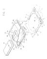
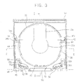
- Figure 2 is an exploded perspective view of a disc cartridge according to an embodiment of the present invention, and Figure 3 shows the disc cartridge fully assembled.
- Figure 4 shows an opening cover coupled with the disc cartridge, and
- Figure 5 is a sectional view showing a disc accommodated in the inner portion of a cartridge case shown in Figure 2 .
- an information recording medium is referred to as a disc. It will be noted, however, that the information recording medium is not exclusively limited to the disc in the present invention.
- the disc cartridge includes a cartridge case 30, a shutter 50, and an opening cover 70.
- a space is defined within the cartridge case 30 and a disc d is accommodated in the space.
- the shutter 50 is disposed on the cartridge case 30 to selectively open/close a spindle opening 30a and an extended opening 30b of the cartridge case 30.
- the opening cover 70 is detachably mounted to a disc entry opening 37 at a rear side of the cartridge case 30.
- the disc cartridge according to the embodiment present invention includes a plurality of sensing holes 30c, 30d, 30e, and 30f, opening/closing means, and disc holding means.
- the plurality of sensing holes 30c, 30d, 30e, and 30f perform the same functions as the plurality of sensing holes 10c, 10d, 10e, and 10f, respectively. Accordingly, as a plurality of sensing switches (not shown) provided to an optical recording/reproducing device are selectively inserted into the sensing holes 30c, 30d, 30e, and 30f, the states of the disc d are determined.
- the opening/closing means selectively opens/closes the sensing holes 30c, 30d, 30e, and 30f, based on the states of the disc d.
- the disc holding means is provided to the opening cover 70 to hold the disc d while the disc is exchanged, thereby enabling the disc d to be withdrawn and/or inserted from/to the cartridge case 30 via the opening cover 70.
- the shutter 50, the sensing holes 30c, 30d, 30e, and 30f, and the sensing hole opening/closing means are not considered to be essential elements in the embodiment of the present invention. Accordingly, the elements are exclusive, but the disc holding means will be described in greater detail hereinafter.
- An arc rib 32 is formed on an inner side of the cartridge case 30 by injection molding to support the disc d.
- the plurality of sensing holes 30c, 30d, 30e, and 30f are formed in a diagonal direction on upper and lower shells of the cartridge case 30, so that the states of the disc d which is accommodated in the cartridge case 30 are sensed by an optical recording/reproducing device (not shown). It is preferable that the plurality of sensing holes 30c, 30d, 30e and 30f may be formed on the upper or lower shell of cartridge case 30 for the cartridge case for a single-sided disc. Additionally, locking recesses 30h are formed at opposite inner sidewalls of the cartridge case 30, more particularly, at a place adjacent to the disc entry opening 37 where the opening cover 70 is attached.
- the arc rib 32 has a diameter greater than the diameter of the disc d, in order to permit the accommodated disc d in the cartridge case 30 to be smoothly rotated.
- the shutter 50 is for opening the spindle opening 30a and the extended opening 30b of the cartridge case 30.
- the shutter 50 is moved in a predetermined direction by shutter opening/closing means (not shown) so that the spindle opening 30a and the extended opening 30b are opened.
- the width W of the shutter 50 is greater than the diameter D of spindle opening 30a
- the diameter D of the spindle opening 30a is greater than the diameter of a turntable and a chucking clamper (not shown) for rotating and chucking the disc d, so that the turntable and the chucking clamper are advanced through the spindle opening 30a, smoothly.
- the opening cover 70 is attached/detached to/from the cartridge case 30 by being pulled out/pushed in, and a pair of locking projections 46 are formed at opposite sides of the opening cover 70 to correspond with the locking recesses 30h of the cartridge case 30. Accordingly, when the opening cover 70 is pushed into the disc entry opening 37 of the cartridge case 30, the locking projections 46 of the opening cover 70 are fixedly locked in the locking recesses 30h of the cartridge case 30, respectively, so that the opening cover 70 is securely attached to the cartridge case 30. Also, tension ribs 48 are formed on both sides of the opening cover 70 to release the locking projections 46 when the opening cover 70 is to be detached from the cartridge case 30. More specifically, if the user pushes the tension ribs 48 while pulling out the opening cover 70, the locking projections 46 are unlocked from the respective locking recesses 30h so that the opening cover 70 is detached from the cartridge case 30.
- opening/closing means for selectively opening/closing the A1 holes 30c is provided to both sides of the opening cover 70, and more particularly, at the places corresponding with the sensing holes 30c, 30d, 30e, and 30f, particularly corresponding to the A1 holes 30c.
- the opening/closing means includes movement holes 30g, rotary arms 52, and tension levers 54.
- the movement holes 30g are formed in the opening cover 70, in a manner that the movement holes 30g include the A1 holes 30c, respectively.
- one A1 hole 30c as shown in Figures 2 and 3 , is formed at a portion of the movement hole 30g.
- Each of the A1 holes 30c is communicated with each of the movement holes 30g which provides a space for the rotary arms 52 to move therein.
- the rotary arms 52 are movably disposed on the opening cover 70, at a place corresponding with the movement holes 30g.
- the tension levers 54 are extended from the opening cover 70 to movably support the rotary arms 52 and to return the rotary arms 52 to their initial positions.
- Stopping projections 56 are integrally formed on the rotary arms 52, and stopping ribs 58 corresponding to the stopping projections 56 as shown in Figure 3 , are formed on the opening cover 70, adjacent to a place corresponding with the A1 holes 30c.
- the stopping projections 56 are stopped by the stopping ribs 58, so that the rotary arms 52 are maintained in a place to where the rotary arms 52 are moved.
- the stopping projections 56 are released from the stopping ribs 58 so that the rotary arms 52 are returned to their initial positions by the tension of the tension ribs 54.
- disc holding means which is the main feature of the present invention, is provided on the opening cover 70 and the cartridge case 30.
- the disc holding means includes a pair of elastic pressing parts 44, supporting ribs 38 and 40, and release means.
- the elastic pressure parts 44 are extended from both sides of the opening cover 70 to define a space (disc accommodating space) therebetween, and have an elasticity toward a middle portion of the opening cover 70 to elastically support the disc d in a lateral direction.
- the supporting ribs 38 and 40 are formed along a disc supporting part of the opening cover 70, and have guide grooves for receiving the edge of the disc d.
- the release means widens the space between the elastic pressure parts 44 elastically supporting the disc d so that the disc d can be rotated smoothly when the opening cover 70 is attached to the cartridge case 30.
- the release means includes receiving ribs 42 formed on the opening cover 70, and intervening members 34 formed on the cartridge case 30.
- the receiving ribs 42 have outwardly inclined surfaces 42a, respectively, which are formed on leading ends of the elastic pressure parts 44.
- the intervening members 34 are wedge-shaped, and are formed on opposite inner sidewalls of the cartridge case 30 at positions corresponding to the receiving ribs 42.
- the intervening members 34 have receiving recesses 34a which have inclined surfaces 34b that correspond with the outwardly inclined surfaces 42a of the receiving ribs 42.
- the supporting ribs are respectively formed as first supporting ribs 38 formed at both elastic pressure parts 44 to support the disc d on the intermediate portion thereof in a lateral direction, and as a second supporting rib 40 formed at the opening cover 70 to support the disc d from the rear part of the cartridge case 30.
- the first supporting ribs 38 may be respectively extended to the second supporting rib. Therefore, the supporting ribs 38 and 40 may be integrally formed along the disc supporting part of the opening cover 70, although such is not shown in the figures.
- the intervening members 34 may be wedge-shaped having the receiving recesses 34a as shown in the figures, or, alternatively, the intervening members 34 may be in cylindrical-shaped, although such is not shown in the figures.
- the cylindrical intervening members push the receiving ribs 42 while the intervening members are slid along the outwardly inclined surfaces 42a of the receiving ribs 42.
- the disc d can be inserted or withdrawn into/from the cartridge case 30 without directly touching the disc d. More specifically, when replacing (or exchanging) the disc d, the opening cover 70 is detached from the cartridge case 30 so that the disc d is withdrawn from the cartridge case 30 together with the opening cover 70 while the disc holding means supports the disc d. It is because when the opening cover 70 is attached to the cartridge case 30, the receiving ribs 42 on the leading ends of the elastic pressure parts 44 widen in the lateral direction by insertion of the receiving ribs 42 into the receiving recesses 34a of the intervening members 34 of the cartridge case 30.
- the elastic pressure parts 44 are returned to their initial positions by withdrawing of the receiving ribs 42 from the receiving recesses 34a of the intervening members 34 so that the elastic pressure parts 44 elastically support the disc d.
- the opening cover 70 including the disc d is attached to the cartridge case 30, so that the receiving ribs 42 of the elastic pressure parts 44 are inserted into the receiving recesses 34a of the intervening members 34 of the cartridge case 30. Accordingly, the elastic pressure parts 44 are forced outward from each other and the disc d can be rotated in the cartridge case smoothly.
- the maximum width between the elastic pressure parts 44 is less than the width of the cartridge case 30, when the elastic pressure parts 44 are forced outward from each other by the release means.
- the disc d which is accommodated in the cartridge case 30 can be withdrawn via the opening cover 70 without being damaged.
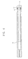
- Figure 4 is a cross-sectional view taken along line I-I of Figure 3 showing the opening cover 70 which is coupled to the cartridge case 30.
- the disc cartridge according to the embodiment of the present invention further includes means for firmly fastening the opening cover 70 to the cartridge case 30, thereby preventing a gap between the opening cover 70 and the cartridge case 30.
- the fastening means includes coupling ribs 81 and rib recesses 82.
- the coupling ribs 81 are formed on upper and lower shells 36a, 36b of the cartridge case 30, respectively, and more specifically at places corresponding to part of the opening cover 70 that attaches to the cartridge case 30.
- the rib recesses 82 are formed in the opening cover 70 to receive the coupling ribs 81.
- the disc cartridge according to the embodiment of the present invention further includes positioning means for positioning the disc d received in the cartridge case 30 upward/downward at an exact position.
- the positioning means includes stepped parts 91 and 92 which are formed on upper and lower inner surfaces of the cartridge case 30 at predetermined heights, respectively.
- the positioning means may include circular bands having a predetermined height that are attached to the upper and lower inner surfaces of the cartridge case 30.
- the heights of the stepped parts 91 and 92, or the height of the circular bands is equal to, or greater than the thickness of the supporting ribs 38.
- the disc d accommodated in the cartridge case 30 Due to the positioning means of the cartridge case 30 having the stepped parts 91 and 92, or the circular bands, the disc d accommodated in the cartridge case 30, is adjusted upward/downward and positioned at the exact position. Accordingly, when the user attempts to take out the disc d accommodated in another cartridge case by using the opening cover 70 which includes the holding means according to the embodiment of the present invention, the user may simply attach the opening cover 70 to the cartridge case 30 of the other disc cartridge. Then, the disc d is withdrawn from the other disc cartridge, while being supported by the holding means of the opening cover 70 of this cartridge case 30.
- the disc cartridge according to the embodiment of the present invention further includes a gripping part 93 which is formed on the front surface of the opening cover 70. Accordingly, the user grips the gripping part 93 by his/her hand and attaches/detaches the opening cover 70 to/from the cartridge case 30 using the gripping part 93.
- Symbols or characters may be printed on the gripping part 93 to indicate a first side and a second side of the disc d. Accordingly, the user may easily distinguish each side of the disc d.
- the user In order to replace the disc d with the bare disc d whose states are verified in the cartridge case 30, the user eliminates a protector rib to protect the information recorded on the disc d, and presses the tension ribs 48 on the opening cover 70 inward and pulls the opening cover 70 out, manually. Accordingly, the locking projections 46 locked into the locking recesses 30h are released, and the opening cover 70 is detached from the cartridge case 30.
- the elastic pressure parts 44 are returned to their initial positions, so that the disc d is elastically supported by the elastic pressure parts 44 and withdrawn together with the opening cover 70. More specifically, when the user slightly pulls out the opening cover 70 while pressing on the tension ribs 48 of the opening cover 70, the receiving ribs 42 are separated from the receiving recesses 34a of the intervening members 34, and accordingly, the elastic pressure parts 44, which have been forced outward from each other in the lateral direction, approach each other to hold the disc d securely.
- the user separates the disc d from the opening cover 70, and places the bare disc d whose states are verified to be supported by the disc holding means of the opening cover 70. Then, the user pushes the opening cover 70 into the disc entry opening 37 of the cartridge case 30 until the locking projections 46 of the opening cover 70 are locked into the locking recesses 30h of the cartridge case 30. Accordingly, the outwardly inclined surfaces 42a of the receiving ribs 42 of the elastic pressure parts 44 come in contact with the inclined surfaces 34b of the intervening members 34, and then received into the receiving recesses 34a of the intervening members 34. As a result, the elastic pressure parts 44 widen outward from each other in the lateral direction, so that the disc d can be rotated in the cartridge case 30, smoothly.
- the opening cover 70 is useful in an adaptor for using a disc of a diameter of 8cm in an optical recording/reproducing device for a disc of a diameter of 12cm.
- the user can accommodate or withdraw a disc into or from the disc cartridge via an opening cover, by attaching or detaching the opening cover, which is capable of holding the disc, with respect to the cartridge case. Accordingly, the user does not need to touch the disc directly while replacing the disc. As a result, the disc is protected from damage which is caused due to the fingerprints, scratches, etc.
- the user has greater convenience in handling the disc without directly touching the disc d by using the opening cover.
Landscapes
- Packaging For Recording Disks (AREA)
- Feeding And Guiding Record Carriers (AREA)
- Holding Or Fastening Of Disk On Rotational Shaft (AREA)
- Optical Record Carriers And Manufacture Thereof (AREA)
Claims (38)
- Kassette für einen Informationsaufzeichnungsträger mit
einem Kassettengehäuse (30) mit einem Raum zur Aufnahme des Informationsaufzeichnungsträgers und einer Öffnung, durch die der Informationsaufzeichnungsträger eingeführt wird,
einer lösbar am Kassettengehäuse (30) anbringbaren Öffnungsabdeckung (70) zum Abdecken der Öffnung, wenn sie am Kassettengehäuse (30) angebracht ist, wobei sich Plattenhaltemittel (44) der Öffnungsabdeckung (70) von gegenüberliegenden Seiten der Öffnungsabdeckung (70) erstrecken, um den Informationsaufzeichnungsträger zu kontaktieren und zu stützen, so dass sich der Informationsaufzeichnungsträger zusammen mit der Öffnungsabdeckung (70) bewegt, wenn sie nicht am Kassettengehäuse (30) angebracht ist, damit der Informationsaufzeichnungsträger durch die Öffnung in den Raum eingeführt werden kann, und
einer Freigabeeinheit (34) zum Ausrücken der Plattenhaltemittel (44), wodurch sich der Informationsaufzeichnungsträger bezüglich der Öffnungsabdeckung (70) bewegen kann, wenn die Öffnungsabdeckung (70) am Kassettengehäuse (30) angebracht ist,
dadurch gekennzeichnet, dass die Plattenhaltemittel (44) geeignet sind, die obere und die untere Seite des Informationsaufzeichnungsträgers in Eingriff zu nehmen. - Kassette nach Anspruch 1, wobei
die Öffnungsabdeckung (70) elastische Druckteile (44) umfasst, die elastisch gegen einen Rand des Informationsaufzeichnungsträgers drücken, um den Informationsaufzeichnungsträger zu halten, wenn die Öffnungsabdeckung (70) nicht am Kassettengehäuse (30) angebracht ist, und
die Freigabeeinheit (34) die elastischen Druckteile (44) kontaktiert, während die Öffnungsabdeckung (70) am Kassettengehäuse (30) angebracht wird, um die elastischen Druckteile (44) voneinander zu trennen, um zu verhindern, dass die elastischen Druckteile (44) elastisch gegen den Rand des Informationsaufzeichnungsträgers drücken. - Kassettengehäuse (30) nach Anspruch 2, wobei die Freigabeeinheit (34) Zwischenelemente (34) umfasst, die an Innenflächen von gegenüberliegenden Seitenwänden des Kassettengehäuses (30) gebildet sind, und
die elastischen Druckteile (44) und/oder die Zwischenelemente (34) bezüglich einer Bewegungsrichtung, wenn die Öffnungsabdeckung (70) am Kassettengehäuse (30) angebracht wird, geneigte Oberflächen haben,
wobei die geneigten Oberflächen die elastischen Druckteile (44) auseinanderzwingen, wenn sich die Öffnungsabdeckung (70) in der Anbringrichtung bewegt. - Kassette für einen Informationsaufzeichnungsträger nach Anspruch 1, 2 oder 3,
wobei sich Abschnitte der Öffnungsabdeckung (70) und des Kassettengehäuses (30) an oberen und unteren Bereichen der Öffnung überlappen, wenn die Öffnungsabdeckung (70) am Kassettengehäuse (30) angebracht ist, damit keine Fremdkörper zum Informationsaufzeichnungsträger gelangen. - Kassette nach Anspruch 4, wobei
das Kassettengehäuse (30) Koppelrippen (81) hat, die an seinen Rändern in der Nähe der Öffnung ausgebildet sind, und
die Öffnungsabdeckung (70) an ihren Rändern ausgebildete Rippenausnehmungen (82) aufweist, wobei die Rippenausnehmungen (82) jeweils die Koppelrippen (81) aufnehmen, wenn die Öffnungsabdeckung (70) am Kassettengehäuse (30) angebracht ist. - Kassette nach Anspruch 5, wobei die Öffnungsabdeckung (70) an den Innenseiten der Rippenausnehmungen (82) Verlängerungen hat, die sich in die Öffnung erstrecken, wenn die Öffnungsabdeckung (70) am Kassettengehäuse (30) angebracht ist, und sich weiter in einer Anbringrichtung der Öffnungsabdeckung (70) erstrecken als Verlängerungen an Außenseiten der Rippenausnehmungen (82).
- Kassette für einen Informationsaufzeichnungsträger nach einem der vorhergehenden Ansprüche,
wobei die Öffnungsabdeckung (70) Verlängerungsteile hat, die den Informationsaufzeichnungsträger halten und führen, wobei die Öffnungsabdeckung (70) linear gleitet, so dass die Verlängerungsteile linear durch die Öffnung in den Raum eintreten, so dass die Öffnungsabdeckung die Öffnung abdeckt, wenn sie am Kassettengehäuse (30) angebracht ist, und der Informationsaufzeichnungsträger im Raum aufgenommen wird. - Kassette nach Anspruch 7, ferner mit Zwischenelementen (34),
wobei die Verlängerungsteile während der linearen Bewegung zu einer angebrachten Position der Öffnungsabdeckung (70) von inneren Seitenwänden des Kassettengehäuses (30) durch Spalten beabstandet sind und die Zwischenelemente (34) die Verlängerungsteile weiter voneinander und in die Spalten bewegen, so dass die Verlängerungsteile den Informationsaufzeichnungsträger freigeben, wenn die Öffnungsabdeckung (70) die angebrachte Position erreicht hat. - Kassette für einen Informationsaufzeichnungsträger nach einem der vorhergehenden Ansprüche, ferner mit
einem Haltemittel, um zu verhindern, dass sich der Informationsaufzeichnungsträger bezüglich der Öffnungsabdeckung (70) bewegt, indem es den Informationsaufzeichnungsträger stützt, wenn der Informationsaufzeichnungsträger im Kassettengehäuse (30) aufgenommen und/oder daraus herausgezogen wird. - Kassette nach Anspruch 9, wobei das Haltemittel einstückig an der Öffnungsabdeckung (70) ausgebildet ist.
- Kassette für einen Informationsaufzeichnungsträger nach Anspruch 9 oder 10, wobei das Haltemittel Folgendes umfasst:ein Paar elastischer Druckteile (44), die elastisch an der Öffnungsabdeckung (70) ausgebildet sind, um den Informationsaufzeichnungsträger elastisch zu stützen, um zu verhindern, dass sich der Informationsaufzeichnungsträger bezüglich der Öffnungsabdeckung (70) bewegt, wenn die Öffnungsabdeckung (70) nicht am Kassettengehäuse (30) angebracht ist, undein Freigabemittel zum Freigeben des Paars elastischer Druckteile (44), wenn die Öffnungsabdeckung (70) am Kassettengehäuse (30) angebracht ist, so dass sich der Informationsaufzeichnungsträger im Kassettengehäuse (30) drehen kann.
- Kassette nach Anspruch 11, wobei das Freigabemittel das Paar elastischer Druckteile (44) auseinanderspreizt und eine maximale Breite zwischen dem Paar elastischer Druckteile (44) weniger als eine Breite des Kassettengehäuses (30) beträgt.
- Kassette nach einem der vorhergehenden Ansprüche, wobei die Öffnungsabdeckung (70) Stützrippen umfasst.
- Kassette nach Anspruch 13, wobei die Stützrippen Führungsnuten zum Führen des Informationsaufzeichnungsträgers haben, wenn der Informationsaufzeichnungsträger in der Öffnungsabdeckung (70) untergebracht wird.
- Kassette für einen Informationsaufzeichnungsträger nach einem der Ansprüche 11, 12 oder 13, wobei die Öffnungsabdeckung (70) Stützrippen zum Stützen des Informationsaufzeichnungsträgers an einer Innenfläche davon hat,
Aufnahmerippen einstückig an jeweiligen vorderen Enden des Paars elastischer Druckteile (44) ausgebildet sind und
an gegenüberliegenden inneren Seitenwänden des Kassettengehäuses (30) ausgebildete Zwischenelemente (34) vorgesehen sind, die jeweils die Aufnahmerippen gleitend kontaktieren, um die Aufnahmerippen zu schieben, wenn die Öffnungsabdeckung (70) in das Kassettengehäuse (30) eingeführt wird, so dass sich das Paar elastischer Druckteile (44) in einer seitlichen Richtung des Informationsaufzeichnungsträgers aufspreizt. - Kassette nach Anspruch 15, wobei
jede der Aufnahmerippen eine nach außen geneigte Oberfläche hat, die einen vorbestimmten Neigungsgrad hat,
jedes der Zwischenelemente (34) keilförmig ist und eine Aufnahmeausnehmung mit einer geneigten Oberfläche hat, die der nach außen geneigten Oberfläche der jeweiligen Aufnahmerippe entspricht, und die Aufnahmerippen gedrückt werden, wenn die nach außen geneigten Oberflächen der Aufnahmerippen und die geneigten Oberflächen der Aufnahmeausnehmungen gleitend miteinander in Kontakt kommen, wenn die Öffnungsabdeckung (70) am Kassettengehäuse (30) angebracht wird. - Kassette nach Anspruch 15, wobei jede der Aufnahmerippen eine nach außen geneigte Oberfläche hat, die einen vorbestimmten Neigungsgrad hat,
jedes der Zwischenelemente (34) zylinderförmig ist und
die Aufnahmerippen gedrückt werden, wenn die zylinderförmigen Zwischenelemente (34) entlang den geneigten Oberflächen der Aufnahmerippen geschoben werden, wenn die Öffnungsabdeckung (70) am Kassettengehäuse (30) angebracht wird. - Kassette nach Anspruch 15, wobei
das Kassettengehäuse (30) in seinen Seitenwänden ausgebildete Verriegelungsausnehmungen umfasst und die Öffnungsabdeckung (70)
den Verriegelungsausnehmungen jeweils entsprechende Verriegelungsvorsprünge, die die jeweiligen Löcher in Eingriff nehmen, wenn die Öffnungsabdeckung (70) am Kassettengehäuse (30) angebracht ist, und
an gegenüberliegenden Seiten der Öffnungsabdeckung (70) ausgebildete Spannungsrippen umfasst, wobei die Verriegelungsvorsprünge die jeweiligen Verriegelungsausnehmungen ausrücken, wenn die Spannungsrippen aufeinander zu gedrückt werden. - Kassette für einen Informationsaufzeichnungsträger nach Anspruch 15, ferner mit
einem Mittel zum festen Befestigen der Öffnungsabdeckung (70) am Kassettengehäuse (30), um einen Spalt zwischen der Öffnungsabdeckung (70) und dem Kassettengehäuse (30) zu vermeiden, wenn die Öffnungsabdeckung (70) am Kassettengehäuse (30) angebracht ist. - Kassette nach Anspruch 19, wobei das Befestigungsmittel der Öffnungsabdeckung (70)
ein Paar Koppelrippen (81), das an einem Abschnitt des Kassettengehäuses (30) zum Anbringen der Öffnungsabdeckung (70) ausgebildet ist, und in der Öffnungsabdeckung (70) ausgebildete Rippenausnehmungen (82) zur jeweiligen Aufnahme der Koppelrippen (81) umfasst. - Kassette für einen Informationsaufzeichnungsträger nach Anspruch 15 oder 19, ferner mit
einem Positionierungsmittel zur Positionierung des im Kassettengehäuse (30) untergebrachten Informationsaufzeichnungsträgers nach oben/unten in einer exakten Position. - Kassette nach Anspruch 21, wobei das Positionierungsmittel an einer oberen und unteren Innenfläche des Kassettengehäuses (30) ausgebildete gestufte Teile umfasst, die jeweils eine vorbestimmte Höhe haben.
- Kassette nach Anspruch 22, wobei die vorbestimmte Höhe jedes der gestuften Teile einer Dicke jeder der Stützrippen entspricht oder etwas größer als diese ist.
- Kassette nach Anspruch 21, wobei das Positionierungsmittel an einer oberen und unteren Innenfläche des Kassettengehäuses (30) ausgebildete kreisförmige Bänder umfasst, die jeweils eine vorbestimmte Höhe haben.
- Kassette nach Anspruch 24, wobei die vorbestimmte Höhe jedes der kreisförmigen Bänder der Dicke jeder der Stützrippen entspricht oder etwas größer als diese ist.
- Kassette nach einem der Ansprüche 21 bis 25, wobei die Öffnungsabdeckung (70) einen Griffteil umfasst, der an einer Vorderfläche davon ausgebildet ist, damit der Benutzer die Öffnungsabdeckung (70) ergreifen kann.
- Kassette nach Anspruch 26, wobei der Griffteil es dem Benutzer ermöglicht, die Öffnungsabdeckung (70) vom Kassettengehäuse (30) wegzuziehen.
- Kassette nach Anspruch 27, wobei der Griffteil mindestens ein auf dem Griffteil aufgedrucktes Symbol zur Andeutung der ersten und zweiten Seite des Informationsaufzeichnungsträgers aufweist.
- Kassette nach Anspruch 21, wobei
das Kassettengehäuse (30)
eine Spindelöffnung und eine verlängerte Öffnung umfasst, damit eine optische Abtastvorrichtung auf den Informationsaufzeichnungsträger zugreifen kann, indem ein vorbestimmter Abschnitt des im Kassettengehäuse (30) untergebrachten Trägers freigelegt wird,
sowie eine Verschlusseinheit, die bezüglich des Kassettengehäuses (30) gleitend angeordnet ist, um die Spindelöffnung und die verlängerte Öffnung gezielt zu öffnen/schließen. - Kassette nach einem der vorhergehenden Ansprüche, wobei
das Kassettengehäuse (30) ein Erfassungsloch zum Erfassen eines Zustands des Informationsaufzeichnungsträgers sowie ein Bewegungsloch umfasst und die Öffnungsabdeckung (70) eine Öffnungs-/Schließeinheit zum gezielten Öffnen und Schließen des Erfassungslochs umfasst, wobei die Öffnungs-/Schließeinheit einen um einen Drehpunkt an der Öffnungsabdeckung (70) beweglich angeordneten Dreharm und an einer Position, die dem Bewegungsloch entspricht, wenn die Öffnungsabdeckung (70) am Kassettengehäuse (30) angebracht ist, einen Spannungshebel zum beweglichen Stützen des Dreharms und Vorspannen des Dreharms in eine Ausgangsposition, einen am Dreharm ausgebildeten Anschlagvorsprung sowie eine an der Öffnungsabdeckung (70) in der Nähe eines Orts, der dem Erfassungsloch entspricht, wenn die Öffnungsabdeckung (70) am Kassettengehäuse (30) angebracht ist, ausgebildete Anschlagrippe aufweist,
wobei die Anschlagrippe den Anschlagvorsprung als Reaktion darauf, dass der Dreharm zum Erfassungsloch bewegt wird, stoppt, um den Dreharm festzuhalten, und der Anschlagvorsprung von der Anschlagrippe freigegeben wird, so dass der Dreharm als Reaktion darauf, dass der Dreharm gedrückt wird, durch den Spannungshebel zur Ausgangsposition zurückkehrt. - Kassette nach einem der vorhergehenden Ansprüche, wobei
das Kassettengehäuse (30) eine Vielzahl von Erfassungslöchern zur Erfassung eines Zustands des Informationsaufzeichnungsträgers und eine entsprechende Vielzahl von Bewegungslöchern umfasst und die Öffnungsabdeckung (70) eine Öffnungs-/Schließeinheit zum gezielten Öffnen und Schließen der Erfassungslöcher umfasst, wobei die Öffnungs-/Schließeinheit Folgendes aufweist:eine Vielzahl von um jeweilige Drehpunkte an der Öffnungsabdeckung (70) beweglich angeordneten Dreharmen und an Positionen, die den Bewegungslöchern entsprechen, wenn die Öffnungsabdeckung (70) am Kassettengehäuse (30) angebracht ist,eine Vielzahl von Spannungshebeln zum beweglichen Stützen der entsprechenden Dreharme und Vorspannen der Dreharme in entsprechende Ausgangspositionen, eine Vielzahl von an den entsprechenden Dreharmen ausgebildeten Anschlagvorsprüngen sowieeine Vielzahl von an der Öffnungsabdeckung (70) in der Nähe von Orten, die den Erfassungslöchern entsprechen, wenn die Öffnungsabdeckung (70) am Kassettengehäuse (30) angebracht ist, ausgebildeten Anschlagrippen,wobei jede Anschlagrippe den entsprechenden Anschlagvorsprung als Reaktion darauf, dass der entsprechende Dreharm zum entsprechenden Erfassungsloch bewegt wird, stoppt, um den Dreharm festzuhalten, und der Anschlagvorsprung von der Anschlagrippe freigegeben wird, so dass der Dreharm als Reaktion darauf, dass der Dreharm gedrückt wird, durch den Spannungshebel zur Ausgangsposition zurückkehrt. - Kassette nach Anspruch 11, wobei
das Kassettengehäuse (30) ein Erfassungsloch zum Erfassen eines Zustands des Informationsaufzeichnungsträgers sowie ein Bewegungsloch umfasst und die Öffnungsabdeckung (70) eine Öffnungs-/Schließeinheit zum gezielten Öffnen und Schließen des Erfassungslochs umfasst, wobei die Öffnungs-/Schließeinheit einen um einen Drehpunkt an der Öffnungsabdeckung (70) beweglich angeordneten Dreharm und an einer Position, die dem Bewegungsloch entspricht, wenn die Öffnungsabdeckung (70) am Kassettengehäuse (30) angebracht ist, einen Spannungshebel zum beweglichen Stützen des Dreharms und Vorspannen des Dreharms in eine Ausgangsposition, einen am Dreharm ausgebildeten Anschlagvorsprung sowie eine an der Öffnungsabdeckung (70) in der Nähe eines Orts, der dem Erfassungsloch entspricht, wenn die Öffnungsabdeckung (70) am Kassettengehäuse (30) angebracht ist, ausgebildete Anschlagrippe aufweist,
wobei die Anschlagrippe den Anschlagvorsprung als Reaktion darauf, dass der Dreharm zum Erfassungsloch bewegt wird, stoppt, um den Dreharm festzuhalten, und der Anschlagvorsprung von der Anschlagrippe freigegeben wird, so dass der Dreharm als Reaktion darauf, dass der Dreharm gedrückt wird, durch den Spannungshebel zur Ausgangsposition zurückkehrt. - Kassette nach Anspruch 11, wobei
das Kassettengehäuse (30) eine Vielzahl von Erfassungslöchern zur Erfassung eines Zustands des Informationsaufzeichnungsträgers und eine entsprechende Vielzahl von Bewegungslöchern umfasst und die Öffnungsabdeckung (70) eine Öffnungs-/Schließeinheit zum gezielten Öffnen und Schließen der Erfassungslöcher umfasst, wobei die Öffnungs-/Schließeinheit Folgendes aufweist:eine Vielzahl von um jeweilige Drehpunkte an der Öffnungsabdeckung (70) beweglich angeordneten Dreharmen und an Positionen, die den Bewegungslöchern entsprechen, wenn die Öffnungsabdeckung (70) am Kassettengehäuse (30) angebracht ist,eine Vielzahl von Spannungshebeln zum beweglichen Stützen der entsprechenden Dreharme und Vorspannen der Dreharme in entsprechende Ausgangspositionen, eine Vielzahl von an den entsprechenden Dreharmen ausgebildeten Anschlagvorsprüngen sowieeine Vielzahl von an der Öffnungsabdeckung (70) in der Nähe von Orten, die den Erfassungslöchern entsprechen, wenn die Öffnungsabdeckung (70) am Kassettengehäuse (30) angebracht ist, ausgebildeten Anschlagrippen,wobei jede Anschlagrippe den entsprechenden Anschlagvorsprung als Reaktion darauf, dass der entsprechende Dreharm zum entsprechenden Erfassungsloch bewegt wird, stoppt, um den Dreharm festzuhalten, und der Anschlagvorsprung von der Anschlagrippe freigegeben wird, so dass der Dreharm als Reaktion darauf, dass der Dreharm gedrückt wird, durch den Spannungshebel zur Ausgangsposition zurückkehrt. - Kassette nach Anspruch 19, wobei das Kassettengehäuse (30) ein Erfassungsloch zum Erfassen eines Zustands des Informationsaufzeichnungsträgers sowie ein Bewegungsloch umfasst und die Öffnungsabdeckung (70) eine Öffnungs-/Schließeinheit zum gezielten Öffnen und Schließen des Erfassungslochs umfasst, wobei die Öffnungs-/Schließeinheit Folgendes aufweist:einen um einen Drehpunkt an der Öffnungsabdeckung (70) beweglich angeordneten Dreharm und an einer Position, die dem Bewegungsloch entspricht, wenn die Öffnungsabdeckung (70) am Kassettengehäuse (30) angebracht ist,einen Spannungshebel zum beweglichen Stützen des Dreharms und Vorspannen des Dreharms in eine Ausgangsposition,einen am Dreharm ausgebildeten Anschlagvorsprung sowie eine an der Öffnungsabdeckung (70) in der Nähe eines Orts, der dem Erfassungsloch entspricht, wenn die Öffnungsabdeckung (70) am Kassettengehäuse (30) angebracht ist, ausgebildete Anschlagrippe,wobei die Anschlagrippe den Anschlagvorsprung als Reaktion darauf, dass der Dreharm zum Erfassungsloch bewegt wird, stoppt, um den Dreharm festzuhalten, und der Anschlagvorsprung von der Anschlagrippe freigegeben wird, so dass der Dreharm als Reaktion darauf, dass der Dreharm gedrückt wird, durch den Spannungshebel zur Ausgangsposition zurückkehrt.
- Kassette nach Anspruch 30, 32 oder 34, wobei das Erfassungsloch ein Al-Loch ist, das anzeigt, ob die Platte bezüglich des Kassettengehäuses (30) ausgetauscht worden ist.
- Kassette nach Anspruch 19, wobei das Kassettengehäuse (30) eine Vielzahl von Erfassungslöchern zur Erfassung eines Zustands des Informationsaufzeichnungsträgers und eine entsprechende Vielzahl von Bewegungslöchern umfasst und
die Öffnungsabdeckung (70) eine Öffnungs-/Schließeinheit zum gezielten Öffnen und Schließen der Erfassungslöcher umfasst, wobei die Öffnungs-/Schließeinheit Folgendes aufweist:
eine Vielzahl von um jeweilige Drehpunkte an der Öffnungsabdeckung (70) beweglich angeordneten Dreharmen und an Positionen, die den Bewegungslöchern entsprechen, wenn die Öffnungsabdeckung (70) am Kassettengehäuse (30) angebracht ist,
eine Vielzahl von Spannungshebeln zum beweglichen Stützen der entsprechenden Dreharme und Vorspannen der Dreharme in entsprechende Ausgangspositionen, eine Vielzahl von an den entsprechenden Dreharmen ausgebildeten Anschlagvorsprüngen sowie eine Vielzahl von an der Öffnungsabdeckung (70) in der Nähe von Orten, die den Erfassungslöchern entsprechen, wenn die Öffnungsabdeckung (70) am Kassettengehäuse (30) angebracht ist, ausgebildeten Anschlagrippen,
wobei jede Anschlagrippe den entsprechenden Anschlagvorsprung als Reaktion darauf, dass der entsprechende Dreharm zum entsprechenden Erfassungsloch bewegt wird, stoppt, um den Dreharm festzuhalten, und der Anschlagvorsprung von der Anschlagrippe freigegeben wird, so dass der Dreharm als Reaktion darauf, dass der Dreharm gedrückt wird, durch den Spannungshebel zur Ausgangsposition zurückkehrt. - Kassette nach Anspruch 18, wobei sich die Spannungsrippen der Öffnungsabdeckung (70) in einer zu den gegenüberliegenden Seiten der Öffnungsabdeckung (70) parallel verlaufenden Richtung erstrecken und sich an Enden von gegenüberliegenden Seiten des Kassettengehäuses (30) befinden, die zu den gegenüberliegenden Seiten der Öffnungsabdeckung (70) parallel verlaufen, wenn die Öffnungsabdeckung (70) am Kassettengehäuse (30) angebracht ist.
- Kassette nach Anspruch 37, wobei die Spannungsrippen zu den gegenüberliegenden Seiten des Kassettengehäuses (30) koplanar verlaufen, wenn die Öffnungsabdeckung (70) am Kassettengehäuse (30) angebracht ist.
Priority Applications (4)
| Application Number | Priority Date | Filing Date | Title |
|---|---|---|---|
| EP02013036A EP1246188A3 (de) | 1998-05-23 | 1999-05-21 | Kassette für Informationsaufzeichnungträger |
| EP02012156A EP1246186B1 (de) | 1998-05-23 | 1999-05-21 | Kassette für Informationsaufzeichnungsträger |
| EP02012157A EP1246187B1 (de) | 1998-05-23 | 1999-05-21 | Kassette für Informationsaufzeichnungsträger |
| EP05004766A EP1557834A3 (de) | 1998-05-23 | 1999-05-21 | Kassette für Informationsaufzeichnungsträger |
Applications Claiming Priority (6)
| Application Number | Priority Date | Filing Date | Title |
|---|---|---|---|
| KR9818684 | 1998-05-23 | ||
| KR19980018684 | 1998-05-23 | ||
| KR9834561 | 1998-08-26 | ||
| KR1019980034561A KR19990086978A (ko) | 1998-05-23 | 1998-08-26 | 인식홀개페수단을가지는기록매체용카트리지 |
| KR1019980037104A KR100412476B1 (ko) | 1998-09-09 | 1998-09-09 | 기록매체용카트리지 |
| KR9837104 | 1998-09-09 |
Related Child Applications (7)
| Application Number | Title | Priority Date | Filing Date |
|---|---|---|---|
| EP02013036A Division EP1246188A3 (de) | 1998-05-23 | 1999-05-21 | Kassette für Informationsaufzeichnungträger |
| EP02012157A Division EP1246187B1 (de) | 1998-05-23 | 1999-05-21 | Kassette für Informationsaufzeichnungsträger |
| EP02012156A Division EP1246186B1 (de) | 1998-05-23 | 1999-05-21 | Kassette für Informationsaufzeichnungsträger |
| EP02012157.0 Division-Into | 2002-06-01 | ||
| EP02012156.2 Division-Into | 2002-06-01 | ||
| EP02013036.5 Division-Into | 2002-06-13 | ||
| EP05004766.1 Division-Into | 2005-03-04 |
Publications (2)
| Publication Number | Publication Date |
|---|---|
| EP0959471A1 EP0959471A1 (de) | 1999-11-24 |
| EP0959471B1 true EP0959471B1 (de) | 2010-03-24 |
Family
ID=36792804
Family Applications (5)
| Application Number | Title | Priority Date | Filing Date |
|---|---|---|---|
| EP05004766A Withdrawn EP1557834A3 (de) | 1998-05-23 | 1999-05-21 | Kassette für Informationsaufzeichnungsträger |
| EP02013036A Withdrawn EP1246188A3 (de) | 1998-05-23 | 1999-05-21 | Kassette für Informationsaufzeichnungträger |
| EP02012156A Expired - Lifetime EP1246186B1 (de) | 1998-05-23 | 1999-05-21 | Kassette für Informationsaufzeichnungsträger |
| EP99303953A Expired - Lifetime EP0959471B1 (de) | 1998-05-23 | 1999-05-21 | Kassette für Informationsaufzeichnungsträger |
| EP02012157A Expired - Lifetime EP1246187B1 (de) | 1998-05-23 | 1999-05-21 | Kassette für Informationsaufzeichnungsträger |
Family Applications Before (3)
| Application Number | Title | Priority Date | Filing Date |
|---|---|---|---|
| EP05004766A Withdrawn EP1557834A3 (de) | 1998-05-23 | 1999-05-21 | Kassette für Informationsaufzeichnungsträger |
| EP02013036A Withdrawn EP1246188A3 (de) | 1998-05-23 | 1999-05-21 | Kassette für Informationsaufzeichnungträger |
| EP02012156A Expired - Lifetime EP1246186B1 (de) | 1998-05-23 | 1999-05-21 | Kassette für Informationsaufzeichnungsträger |
Family Applications After (1)
| Application Number | Title | Priority Date | Filing Date |
|---|---|---|---|
| EP02012157A Expired - Lifetime EP1246187B1 (de) | 1998-05-23 | 1999-05-21 | Kassette für Informationsaufzeichnungsträger |
Country Status (11)
| Country | Link |
|---|---|
| US (8) | US6445677B1 (de) |
| EP (5) | EP1557834A3 (de) |
| JP (4) | JP3302338B2 (de) |
| CN (4) | CN1265383C (de) |
| BR (1) | BR9901628A (de) |
| DE (3) | DE69933950T2 (de) |
| ID (1) | ID22601A (de) |
| MY (1) | MY122186A (de) |
| RU (1) | RU2193240C2 (de) |
| SG (1) | SG94718A1 (de) |
| TW (1) | TW430787B (de) |
Families Citing this family (19)
| Publication number | Priority date | Publication date | Assignee | Title |
|---|---|---|---|---|
| DE69800551T2 (de) | 1997-12-16 | 2001-06-21 | Matsushita Electric Industrial Co., Ltd. | Plattenkassette |
| SG94718A1 (en) * | 1998-05-23 | 2003-03-18 | Samsung Electronics Co Ltd | Cartridge for an information recording medium |
| US6418113B1 (en) | 1998-11-05 | 2002-07-09 | Tdk Corporation | Disk cartridge |
| JP3840346B2 (ja) * | 1999-01-08 | 2006-11-01 | アルプス電気株式会社 | 光ディスクカートリッジ |
| JP2000207864A (ja) | 1999-01-08 | 2000-07-28 | Alps Electric Co Ltd | 光ディスクカ―トリッジ |
| KR100692770B1 (ko) | 1999-01-23 | 2007-03-09 | 엘지전자 주식회사 | 디스크 카트리지 및 그 제조방법 |
| DE60037729T2 (de) | 1999-06-04 | 2008-06-05 | Matsushita Electric Industrial Co., Ltd., Kadoma | Plattenkassette |
| JP2003059228A (ja) * | 2001-08-21 | 2003-02-28 | Fuji Photo Film Co Ltd | ディスクカートリッジ |
| TWI244072B (en) * | 2002-03-20 | 2005-11-21 | Samsung Electronics Co Ltd | Disc cartridge |
| US20030193884A1 (en) * | 2002-04-16 | 2003-10-16 | Louie James K. | Optical disk storage media identification |
| JP2004087030A (ja) * | 2002-08-28 | 2004-03-18 | Fuji Photo Film Co Ltd | ディスクカートリッジ |
| US20060095156A1 (en) * | 2004-10-20 | 2006-05-04 | Baiada R M | Method and system for tactical airline system management |
| JP2006268913A (ja) * | 2005-03-22 | 2006-10-05 | Fuji Photo Film Co Ltd | 記録ディスクカートリッジ |
| USD559578S1 (en) * | 2005-08-31 | 2008-01-15 | Nexpak Corporation | Grip bar for slide-out media storage container |
| USD563414S1 (en) * | 2005-10-21 | 2008-03-04 | Vtech Electronics, Ltd. | Data disc enclosure |
| ES2265789B1 (es) * | 2006-03-02 | 2008-02-01 | Saint-Gobain Calmar, S.A. | Bomba pulverizadora aplanada. |
| BG924U1 (en) * | 2006-12-04 | 2007-10-31 | Александър ПАНАЙОТОВ | PACKAGING FOR STORAGE OF OPTICAL BACKGROUND INFORMATION |
| US8307387B2 (en) * | 2010-03-30 | 2012-11-06 | Panasonic Corporation | Disk case and determining method thereof |
| US8910182B2 (en) * | 2011-05-27 | 2014-12-09 | Microsoft Corporation | Managing and simplifying distributed applications |
Family Cites Families (74)
| Publication number | Priority date | Publication date | Assignee | Title |
|---|---|---|---|---|
| US3951264A (en) * | 1974-10-29 | 1976-04-20 | Dynastor, Inc. | Flexible disc cartridge |
| US4109919A (en) * | 1976-12-20 | 1978-08-29 | Rca Corporation | Package actuated record extracting mechanism for a video disc player |
| GB1596624A (en) * | 1976-12-20 | 1981-08-26 | Rca Corp | Record handling system for a disc player |
| JPS6141171Y2 (de) * | 1980-10-09 | 1986-11-22 | ||
| US4463850A (en) * | 1983-05-10 | 1984-08-07 | Rca Corporation | Video disc caddy |
| US4707821A (en) * | 1983-11-08 | 1987-11-17 | U.S. Philips Corporation | Disc holder for a rigid audio and/or video disc |
| JPS6168782A (ja) * | 1984-09-12 | 1986-04-09 | Sony Corp | デイスクカ−トリツジ |
| US4609105A (en) * | 1984-09-27 | 1986-09-02 | Storage Technology Partners Ii | Information recording disk cartridge protective structure |
| JPS60229286A (ja) * | 1985-04-09 | 1985-11-14 | Hitachi Maxell Ltd | テープカートリツジ |
| US4702369A (en) * | 1986-01-31 | 1987-10-27 | Cinram Ltd./Ltee. | Storage container for records or the like |
| NL8600809A (nl) | 1986-03-28 | 1987-10-16 | Philips Nv | Methode om een matrijs te voorzien van een loslaag. |
| JPH056607Y2 (de) * | 1986-04-17 | 1993-02-19 | ||
| US4773058A (en) * | 1986-10-27 | 1988-09-20 | Eastman Kodak Company | Disk handling system and apparatus |
| EP0267644A1 (de) * | 1986-11-03 | 1988-05-18 | Koninklijke Philips Electronics N.V. | System für Aufnahme/Wiedergabe von Informationen auf eine/von einer Platte mit Plattenkassette und Gerät |
| NL8701345A (nl) * | 1987-06-10 | 1989-01-02 | Philips Nv | Houder bestemd voor het opnemen van een plaat, alsmede verpakking omvattende een dergelijke houder met een daarin opgenomen plaat. |
| US4819114A (en) * | 1987-12-16 | 1989-04-04 | Eastman Kodak Company | Write-protected data storage disk assembly |
| NL8800820A (nl) | 1988-03-31 | 1989-10-16 | Philips Nv | Cassette. |
| JPH02214081A (ja) * | 1989-02-13 | 1990-08-27 | Gunma Nippon Denki Kk | 光ディスク用カートリッジ |
| JPH02140682U (de) * | 1989-04-21 | 1990-11-26 | ||
| US5140489A (en) * | 1989-10-30 | 1992-08-18 | Eastman Kodak Company | Disk cartridge adapted for use with different disk drives |
| KR960013773B1 (ko) * | 1990-01-29 | 1996-10-10 | 다이닛뽕 인사쓰 가부시기가이샤 | 디스크카트리지 |
| JP2584170B2 (ja) * | 1991-12-09 | 1997-02-19 | 松下電器産業株式会社 | ディスクカートリッジ |
| AU665986B2 (en) * | 1992-03-31 | 1996-01-25 | Sony Corporation | Casing for housing disc cartridge and method for packaging the casing |
| US5768253A (en) * | 1992-05-15 | 1998-06-16 | Cd Plant Tecval S.A. | Disc cartridge for accommodating recording discs |
| JP3332043B2 (ja) | 1992-10-30 | 2002-10-07 | 日立マクセル株式会社 | デイスクカートリツジ |
| JPH06168561A (ja) * | 1992-11-30 | 1994-06-14 | Hitachi Maxell Ltd | ディスクカートリッジ |
| US5537389A (en) * | 1992-11-30 | 1996-07-16 | Hitachi Maxwell, Ltd. | Disk cartridge having a single closing energizer for closing two independently opened shutters |
| JPH06168566A (ja) | 1992-11-30 | 1994-06-14 | Hitachi Maxell Ltd | ディスクカートリッジ |
| JP2643750B2 (ja) * | 1993-01-20 | 1997-08-20 | 日本電気株式会社 | 光ディスクカートリッジ |
| GB9317056D0 (en) * | 1993-08-17 | 1993-09-29 | Gloger Klaus W | A disc container |
| JPH0773633A (ja) * | 1993-09-01 | 1995-03-17 | Nec Gumma Ltd | 光ディスクカートリッジ |
| JPH087429A (ja) * | 1994-06-13 | 1996-01-12 | Yamaha Corp | ディスクローディングシステム、ディスクローディングアダプタおよびディスクドライブ装置 |
| US5499233A (en) * | 1994-06-20 | 1996-03-12 | International Business Machines Corporation | Optical disk carrier with write-protect mechanism |
| US5526337A (en) * | 1994-06-30 | 1996-06-11 | Tamarack Storage Devices | Holographic storage media package |
| JPH0863929A (ja) * | 1994-08-18 | 1996-03-08 | Mitsubishi Chem Corp | 光ディスク用カートリッジ |
| US5548571A (en) * | 1994-10-03 | 1996-08-20 | Eastman Kodak Company | Method and apparatus for identifying data storage disks |
| CN1088893C (zh) * | 1994-12-29 | 2002-08-07 | 索尼公司 | 磁盘盒 |
| US5581540A (en) * | 1995-02-08 | 1996-12-03 | International Business Machines Corporation | Single disk write protection system for multiple-disk cartridge |
| US5786263A (en) * | 1995-04-04 | 1998-07-28 | Motorola, Inc. | Method for forming a trench isolation structure in an integrated circuit |
| JPH08297942A (ja) * | 1995-04-24 | 1996-11-12 | Kao Corp | 光ディスク収納ケース |
| WO1997011463A1 (en) * | 1995-09-21 | 1997-03-27 | Matsushita Electric Industrial Co., Ltd. | Cartridge with removable disk |
| JP3462318B2 (ja) * | 1995-10-13 | 2003-11-05 | 株式会社東芝 | ディスクカートリッジ装置 |
| JP3491427B2 (ja) * | 1996-02-09 | 2004-01-26 | ソニー株式会社 | ディスクカートリッジ |
| JPH09219080A (ja) * | 1996-02-14 | 1997-08-19 | Hitachi Maxell Ltd | ディスクカートリッジ |
| JP3516089B2 (ja) * | 1996-02-26 | 2004-04-05 | 日立マクセル株式会社 | ディスクカートリッジ |
| JP3491118B2 (ja) * | 1996-03-28 | 2004-01-26 | 日立マクセル株式会社 | ディスクカートリッジ |
| JPH103767A (ja) * | 1996-06-12 | 1998-01-06 | Hitachi Ltd | ディスクカートリッジ |
| JP3487086B2 (ja) * | 1996-07-12 | 2004-01-13 | ソニー株式会社 | ディスク保持体 |
| TW396334B (en) * | 1996-07-12 | 2000-07-01 | Sony Corp | Disk tray and tray allocation box |
| JPH1050025A (ja) * | 1996-07-31 | 1998-02-20 | Pioneer Electron Corp | ディスクカートリッジ |
| JPH1064237A (ja) * | 1996-08-20 | 1998-03-06 | Toshiba Corp | 情報記憶媒体のカートリッジ装置 |
| JPH1097777A (ja) * | 1996-09-20 | 1998-04-14 | Sony Corp | ディスクカートリッジ |
| JP3626297B2 (ja) * | 1996-09-30 | 2005-03-02 | 株式会社東芝 | ディスクカートリッジ |
| EP0833330A1 (de) * | 1996-09-30 | 1998-04-01 | Kabushiki Kaisha Toshiba | Plattenkassette |
| JPH10106211A (ja) * | 1996-09-30 | 1998-04-24 | Toshiba Corp | ディスクカートリッジ |
| JP3570111B2 (ja) * | 1996-10-11 | 2004-09-29 | ソニー株式会社 | ディスク収納ケースおよびディスクトレイ |
| TW385433B (en) * | 1996-10-28 | 2000-03-21 | Dainippon Printing Co Ltd | A cartridge case for a disk-shaped recording medium and a disk cartridge |
| JP3517728B2 (ja) * | 1996-11-07 | 2004-04-12 | 日立マクセル株式会社 | ディスクカートリッジ |
| JP3367017B2 (ja) * | 1996-11-07 | 2003-01-14 | 日立マクセル株式会社 | ディスクカートリッジ |
| JP3632805B2 (ja) * | 1996-11-07 | 2005-03-23 | 日立マクセル株式会社 | ディスクカートリッジ |
| US6108298A (en) * | 1997-04-15 | 2000-08-22 | Tdk Corporation | Disc cartridge |
| US6205115B1 (en) * | 1997-09-10 | 2001-03-20 | Tdk Corporation | Disc cartridge |
| EP0921526B1 (de) * | 1997-12-06 | 2003-05-21 | Samsung Electronics Co., Ltd. | Plattenkassette mit zu öffnendem/schliessendem Sensorloch und Antriebsgerät und -verfahren dazu |
| DE69800551T2 (de) * | 1997-12-16 | 2001-06-21 | Matsushita Electric Industrial Co., Ltd. | Plattenkassette |
| JP3024625B2 (ja) | 1998-01-21 | 2000-03-21 | 株式会社日立製作所 | ディスクカートリッジ |
| JP3024626B2 (ja) | 1998-02-13 | 2000-03-21 | 株式会社日立製作所 | ディスクカートリッジ |
| TW412728B (en) * | 1998-01-21 | 2000-11-21 | Hitachi Ltd | Disk cartridge |
| JPH11238337A (ja) * | 1998-02-20 | 1999-08-31 | Hitachi Ltd | ディスクカートリッジ |
| US5878879A (en) * | 1998-03-13 | 1999-03-09 | Liao; Chung Kuang | Cassette holder having easily removable insert |
| SG94718A1 (en) * | 1998-05-23 | 2003-03-18 | Samsung Electronics Co Ltd | Cartridge for an information recording medium |
| US6529471B1 (en) * | 1998-07-15 | 2003-03-04 | Lg Electronics Inc. | Disc protection casing and drive for receiving the same |
| US6152102A (en) | 1999-03-22 | 2000-11-28 | Brunswick Corporation | Throttle control system for a stratified charge internal combustion engine |
| DE60037729T2 (de) * | 1999-06-04 | 2008-06-05 | Matsushita Electric Industrial Co., Ltd., Kadoma | Plattenkassette |
| JP2001210043A (ja) * | 2000-01-26 | 2001-08-03 | Nec Corp | ディスクカートリッジ |
-
1999
- 1999-05-14 SG SG9902447A patent/SG94718A1/en unknown
- 1999-05-17 US US09/313,787 patent/US6445677B1/en not_active Expired - Lifetime
- 1999-05-20 RU RU99110391/28A patent/RU2193240C2/ru active
- 1999-05-20 CN CNB021015155A patent/CN1265383C/zh not_active Expired - Lifetime
- 1999-05-20 ID IDP990464D patent/ID22601A/id unknown
- 1999-05-20 CN CNB021015147A patent/CN100385555C/zh not_active Expired - Lifetime
- 1999-05-20 CN CN99106785A patent/CN1122275C/zh not_active Expired - Lifetime
- 1999-05-20 CN CNB021015139A patent/CN1248230C/zh not_active Expired - Lifetime
- 1999-05-21 DE DE69933950T patent/DE69933950T2/de not_active Expired - Lifetime
- 1999-05-21 BR BR9901628-1A patent/BR9901628A/pt not_active Application Discontinuation
- 1999-05-21 EP EP05004766A patent/EP1557834A3/de not_active Withdrawn
- 1999-05-21 DE DE69942163T patent/DE69942163D1/de not_active Expired - Lifetime
- 1999-05-21 TW TW088108341A patent/TW430787B/zh not_active IP Right Cessation
- 1999-05-21 DE DE69934148T patent/DE69934148T2/de not_active Expired - Lifetime
- 1999-05-21 EP EP02013036A patent/EP1246188A3/de not_active Withdrawn
- 1999-05-21 EP EP02012156A patent/EP1246186B1/de not_active Expired - Lifetime
- 1999-05-21 EP EP99303953A patent/EP0959471B1/de not_active Expired - Lifetime
- 1999-05-21 EP EP02012157A patent/EP1246187B1/de not_active Expired - Lifetime
- 1999-05-22 MY MYPI99002033A patent/MY122186A/en unknown
- 1999-05-24 JP JP14407199A patent/JP3302338B2/ja not_active Expired - Lifetime
-
2001
- 2001-07-09 JP JP2001208504A patent/JP2002074882A/ja active Pending
- 2001-07-09 JP JP2001208503A patent/JP2002074881A/ja active Pending
- 2001-07-09 JP JP2001208505A patent/JP2002074883A/ja active Pending
- 2001-09-12 US US09/949,870 patent/US6728200B2/en not_active Expired - Lifetime
- 2001-09-28 US US09/964,632 patent/US6438099B2/en not_active Expired - Lifetime
-
2003
- 2003-10-03 US US10/677,220 patent/US6912724B2/en not_active Expired - Lifetime
- 2003-10-06 US US10/678,257 patent/US6931655B2/en not_active Expired - Lifetime
-
2005
- 2005-05-12 US US11/127,196 patent/US7185351B2/en not_active Expired - Lifetime
- 2005-11-01 US US11/262,727 patent/US7222352B2/en not_active Expired - Lifetime
-
2007
- 2007-04-04 US US11/696,440 patent/US7519981B2/en not_active Expired - Fee Related
Also Published As
Similar Documents
| Publication | Publication Date | Title |
|---|---|---|
| US7519981B2 (en) | Cartridge for an information recording medium | |
| EP0973161B1 (de) | Plattenadapter sowie Methode und Vorrichtung zum Antrieb desselben | |
| US5831965A (en) | Cartridge changing device | |
| HK1059144B (en) | Cartridge for an information recording medium | |
| KR20000012099A (ko) | 디스크 카트리지의 수납 케이스 | |
| KR19990086978A (ko) | 인식홀개페수단을가지는기록매체용카트리지 | |
| KR100200833B1 (ko) | 디스크 카트리지 수납장치 | |
| KR100412476B1 (ko) | 기록매체용카트리지 | |
| HK1059145B (en) | Cartridge for an information recording medium | |
| HK1024089B (en) | Cartridge for an information recording medium | |
| HK1059143B (en) | Cartridge for an information recording medium | |
| KR100362368B1 (ko) | 디스크수납용어댑터와그구동방법및장치 |
Legal Events
| Date | Code | Title | Description |
|---|---|---|---|
| PUAI | Public reference made under article 153(3) epc to a published international application that has entered the european phase |
Free format text: ORIGINAL CODE: 0009012 |
|
| 17P | Request for examination filed |
Effective date: 19990602 |
|
| AK | Designated contracting states |
Kind code of ref document: A1 Designated state(s): DE FR GB NL |
|
| AX | Request for extension of the european patent |
Free format text: AL;LT;LV;MK;RO;SI |
|
| AKX | Designation fees paid |
Free format text: DE FR GB NL |
|
| 17Q | First examination report despatched |
Effective date: 20050707 |
|
| GRAP | Despatch of communication of intention to grant a patent |
Free format text: ORIGINAL CODE: EPIDOSNIGR1 |
|
| RIN1 | Information on inventor provided before grant (corrected) |
Inventor name: CHOI, HAN-KOOK Inventor name: KO, JUNG-WAN Inventor name: SEO, YOUNG-SUN Inventor name: PARK, IN-SIK Inventor name: PARK, JONG-PIL |
|
| GRAS | Grant fee paid |
Free format text: ORIGINAL CODE: EPIDOSNIGR3 |
|
| GRAA | (expected) grant |
Free format text: ORIGINAL CODE: 0009210 |
|
| AK | Designated contracting states |
Kind code of ref document: B1 Designated state(s): DE FR GB NL |
|
| REG | Reference to a national code |
Ref country code: GB Ref legal event code: FG4D |
|
| REF | Corresponds to: |
Ref document number: 69942163 Country of ref document: DE Date of ref document: 20100506 Kind code of ref document: P |
|
| REG | Reference to a national code |
Ref country code: NL Ref legal event code: T3 |
|
| PLBE | No opposition filed within time limit |
Free format text: ORIGINAL CODE: 0009261 |
|
| STAA | Information on the status of an ep patent application or granted ep patent |
Free format text: STATUS: NO OPPOSITION FILED WITHIN TIME LIMIT |
|
| 26N | No opposition filed |
Effective date: 20101228 |
|
| REG | Reference to a national code |
Ref country code: FR Ref legal event code: PLFP Year of fee payment: 18 |
|
| REG | Reference to a national code |
Ref country code: FR Ref legal event code: PLFP Year of fee payment: 19 |
|
| REG | Reference to a national code |
Ref country code: FR Ref legal event code: PLFP Year of fee payment: 20 |
|
| PGFP | Annual fee paid to national office [announced via postgrant information from national office to epo] |
Ref country code: GB Payment date: 20180321 Year of fee payment: 20 |
|
| PGFP | Annual fee paid to national office [announced via postgrant information from national office to epo] |
Ref country code: NL Payment date: 20180419 Year of fee payment: 20 |
|
| PGFP | Annual fee paid to national office [announced via postgrant information from national office to epo] |
Ref country code: DE Payment date: 20180418 Year of fee payment: 20 |
|
| PGFP | Annual fee paid to national office [announced via postgrant information from national office to epo] |
Ref country code: FR Payment date: 20180420 Year of fee payment: 20 |
|
| REG | Reference to a national code |
Ref country code: DE Ref legal event code: R071 Ref document number: 69942163 Country of ref document: DE |
|
| REG | Reference to a national code |
Ref country code: NL Ref legal event code: MK Effective date: 20190520 |
|
| REG | Reference to a national code |
Ref country code: GB Ref legal event code: PE20 Expiry date: 20190520 |
|
| PG25 | Lapsed in a contracting state [announced via postgrant information from national office to epo] |
Ref country code: GB Free format text: LAPSE BECAUSE OF EXPIRATION OF PROTECTION Effective date: 20190520 |