EP0959763B1 - A low thermal capacity device for high precision pocket-size spirometry and other applications - Google Patents
A low thermal capacity device for high precision pocket-size spirometry and other applications Download PDFInfo
- Publication number
- EP0959763B1 EP0959763B1 EP97900020A EP97900020A EP0959763B1 EP 0959763 B1 EP0959763 B1 EP 0959763B1 EP 97900020 A EP97900020 A EP 97900020A EP 97900020 A EP97900020 A EP 97900020A EP 0959763 B1 EP0959763 B1 EP 0959763B1
- Authority
- EP
- European Patent Office
- Prior art keywords
- pulses
- circuit
- temperature
- heating
- bridge
- Prior art date
- Legal status (The legal status is an assumption and is not a legal conclusion. Google has not performed a legal analysis and makes no representation as to the accuracy of the status listed.)
- Expired - Lifetime
Links
- 238000013125 spirometry Methods 0.000 title claims description 8
- 238000010438 heat treatment Methods 0.000 claims abstract description 24
- 238000006243 chemical reaction Methods 0.000 claims abstract description 7
- 230000036760 body temperature Effects 0.000 claims abstract description 4
- 238000005259 measurement Methods 0.000 claims description 28
- 239000012530 fluid Substances 0.000 claims description 11
- 239000011888 foil Substances 0.000 claims description 10
- 239000002184 metal Substances 0.000 claims description 4
- 229910052751 metal Inorganic materials 0.000 claims description 4
- 238000005096 rolling process Methods 0.000 claims description 4
- 239000012212 insulator Substances 0.000 claims description 3
- 239000002131 composite material Substances 0.000 claims description 2
- 230000008878 coupling Effects 0.000 claims description 2
- 238000010168 coupling process Methods 0.000 claims description 2
- 238000005859 coupling reaction Methods 0.000 claims description 2
- 238000000691 measurement method Methods 0.000 claims description 2
- 239000007787 solid Substances 0.000 claims description 2
- KDLHZDBZIXYQEI-UHFFFAOYSA-N Palladium Chemical compound [Pd] KDLHZDBZIXYQEI-UHFFFAOYSA-N 0.000 abstract description 16
- 229910052739 hydrogen Inorganic materials 0.000 abstract description 10
- 239000001257 hydrogen Substances 0.000 abstract description 10
- UFHFLCQGNIYNRP-UHFFFAOYSA-N Hydrogen Chemical compound [H][H] UFHFLCQGNIYNRP-UHFFFAOYSA-N 0.000 abstract description 7
- 229910052763 palladium Inorganic materials 0.000 abstract description 5
- 241000264877 Hippospongia communis Species 0.000 description 15
- 238000000034 method Methods 0.000 description 9
- 238000012360 testing method Methods 0.000 description 5
- XLYOFNOQVPJJNP-UHFFFAOYSA-N water Chemical compound O XLYOFNOQVPJJNP-UHFFFAOYSA-N 0.000 description 5
- 238000010586 diagram Methods 0.000 description 4
- 230000003993 interaction Effects 0.000 description 4
- 210000004072 lung Anatomy 0.000 description 4
- 239000000758 substrate Substances 0.000 description 4
- 230000003111 delayed effect Effects 0.000 description 3
- 238000002474 experimental method Methods 0.000 description 3
- 239000007789 gas Substances 0.000 description 3
- 230000008569 process Effects 0.000 description 3
- 230000035945 sensitivity Effects 0.000 description 3
- 229910001220 stainless steel Inorganic materials 0.000 description 3
- 239000010935 stainless steel Substances 0.000 description 3
- 238000009834 vaporization Methods 0.000 description 3
- 238000010521 absorption reaction Methods 0.000 description 2
- 230000033228 biological regulation Effects 0.000 description 2
- 239000008280 blood Substances 0.000 description 2
- 210000004369 blood Anatomy 0.000 description 2
- 238000007707 calorimetry Methods 0.000 description 2
- 238000004140 cleaning Methods 0.000 description 2
- 230000001276 controlling effect Effects 0.000 description 2
- 230000004199 lung function Effects 0.000 description 2
- 238000012544 monitoring process Methods 0.000 description 2
- BASFCYQUMIYNBI-UHFFFAOYSA-N platinum Chemical compound [Pt] BASFCYQUMIYNBI-UHFFFAOYSA-N 0.000 description 2
- 230000000241 respiratory effect Effects 0.000 description 2
- 229920006395 saturated elastomer Polymers 0.000 description 2
- 230000006641 stabilisation Effects 0.000 description 2
- 229910001369 Brass Inorganic materials 0.000 description 1
- 230000006978 adaptation Effects 0.000 description 1
- 238000004458 analytical method Methods 0.000 description 1
- 210000004204 blood vessel Anatomy 0.000 description 1
- 239000010951 brass Substances 0.000 description 1
- 238000004364 calculation method Methods 0.000 description 1
- 239000000919 ceramic Substances 0.000 description 1
- 230000008859 change Effects 0.000 description 1
- 238000001311 chemical methods and process Methods 0.000 description 1
- 239000003795 chemical substances by application Substances 0.000 description 1
- 239000011248 coating agent Substances 0.000 description 1
- 238000000576 coating method Methods 0.000 description 1
- 238000009833 condensation Methods 0.000 description 1
- 230000005494 condensation Effects 0.000 description 1
- 239000004020 conductor Substances 0.000 description 1
- 238000001816 cooling Methods 0.000 description 1
- 230000002596 correlated effect Effects 0.000 description 1
- 230000003247 decreasing effect Effects 0.000 description 1
- 239000000645 desinfectant Substances 0.000 description 1
- 230000000249 desinfective effect Effects 0.000 description 1
- 238000009792 diffusion process Methods 0.000 description 1
- 230000003670 easy-to-clean Effects 0.000 description 1
- 230000000694 effects Effects 0.000 description 1
- 230000007613 environmental effect Effects 0.000 description 1
- 239000001307 helium Substances 0.000 description 1
- 229910052734 helium Inorganic materials 0.000 description 1
- SWQJXJOGLNCZEY-UHFFFAOYSA-N helium atom Chemical compound [He] SWQJXJOGLNCZEY-UHFFFAOYSA-N 0.000 description 1
- 150000004678 hydrides Chemical class 0.000 description 1
- 230000006872 improvement Effects 0.000 description 1
- 238000001727 in vivo Methods 0.000 description 1
- 238000004519 manufacturing process Methods 0.000 description 1
- 230000007170 pathology Effects 0.000 description 1
- 229910052697 platinum Inorganic materials 0.000 description 1
- 238000012545 processing Methods 0.000 description 1
- 230000005855 radiation Effects 0.000 description 1
- 238000009877 rendering Methods 0.000 description 1
- 230000029058 respiratory gaseous exchange Effects 0.000 description 1
- 230000004044 response Effects 0.000 description 1
- 238000000926 separation method Methods 0.000 description 1
- 238000001179 sorption measurement Methods 0.000 description 1
- 238000004659 sterilization and disinfection Methods 0.000 description 1
- 210000000115 thoracic cavity Anatomy 0.000 description 1
Images




Classifications
-
- G—PHYSICS
- G01—MEASURING; TESTING
- G01F—MEASURING VOLUME, VOLUME FLOW, MASS FLOW OR LIQUID LEVEL; METERING BY VOLUME
- G01F1/00—Measuring the volume flow or mass flow of fluid or fluent solid material wherein the fluid passes through a meter in a continuous flow
- G01F1/68—Measuring the volume flow or mass flow of fluid or fluent solid material wherein the fluid passes through a meter in a continuous flow by using thermal effects
- G01F1/696—Circuits therefor, e.g. constant-current flow meters
- G01F1/698—Feedback or rebalancing circuits, e.g. self heated constant temperature flowmeters
- G01F1/6986—Feedback or rebalancing circuits, e.g. self heated constant temperature flowmeters with pulsed heating, e.g. dynamic methods
-
- A—HUMAN NECESSITIES
- A61—MEDICAL OR VETERINARY SCIENCE; HYGIENE
- A61B—DIAGNOSIS; SURGERY; IDENTIFICATION
- A61B5/00—Measuring for diagnostic purposes; Identification of persons
- A61B5/08—Measuring devices for evaluating the respiratory organs
- A61B5/087—Measuring breath flow
- A61B5/0878—Measuring breath flow using temperature sensing means
-
- G—PHYSICS
- G01—MEASURING; TESTING
- G01F—MEASURING VOLUME, VOLUME FLOW, MASS FLOW OR LIQUID LEVEL; METERING BY VOLUME
- G01F1/00—Measuring the volume flow or mass flow of fluid or fluent solid material wherein the fluid passes through a meter in a continuous flow
- G01F1/68—Measuring the volume flow or mass flow of fluid or fluent solid material wherein the fluid passes through a meter in a continuous flow by using thermal effects
- G01F1/684—Structural arrangements; Mounting of elements, e.g. in relation to fluid flow
- G01F1/688—Structural arrangements; Mounting of elements, e.g. in relation to fluid flow using a particular type of heating, cooling or sensing element
- G01F1/69—Structural arrangements; Mounting of elements, e.g. in relation to fluid flow using a particular type of heating, cooling or sensing element of resistive type
- G01F1/692—Thin-film arrangements
Definitions
- This invention refers to the fields of spirometry measurements and in particular to thermostatic control of pneumotacographs. Furthermore, it can also be conveniently used in both micro-calorimetry and in the measurement of flow rates of a fluid along a pipe.
- Lung volume is one of the most informative measurements that can be performed from the breath. Variations of volume allow estimating and predicting the profile of the lung functionality and are therefore crucial towards a proper and prompt treatment. Since lung volume is on the order of several liters, it is impractical to measure it directly.
- the flow can be measured instead - e.g. from the pressure drop across a resistance - and then integrated to obtain volume readings. This can be done reliably only to the extent in which the flow-measuring device is linear and accurate. Measuring flow instead of volume allows reducing the size and weight of spirometric devices.
- measuring flow entails a variety of technical problems mainly related to thermostatic regulation, which we examine below.
- Fleisch proposed what is still one of the most accurate methods to perform spirometry by means of measuring laminar flows.
- Fleisch used a honeycomb structure.
- the most common form of honeycomb structure consists of a cylinder made by coupling and rolling up two thin metal sheets, one corrugated and the other smooth, around a tiny hub.
- the honeycomb structure is one of the many possible physical filters capable of maintaining a laminar flow in a conduit, so that pressure drop and flow rate values are linearly correlated.
- several other different structures have been introduced. The most widely known is that of the fine mesh screen structure. This is lighter than the honeycomb structure but "frequent cleaning and re-calibration are considered essential to preserve accuracy in measurements"( 1 ).
- the temperature of the air inside human lungs is 37°C and saturated with water vapor. When exhaled, air condenses and releases its vaporisation enthalpy.
- the present state-of-the-art provides a wide choice of solutions that exhibit technical drawbacks, which have heavily delayed the production of a simple, reliable, small, lightweight, low-power, easy-to-clean and truly portable pneumotach system.
- the purpose of this invention is to produce a device with at least one active element featuring low heat capacity, that may be used especially as a space-saving instrument for measuring and controlling heat exchanges.
- the invention relates, as defined in claim 1, to a device based on an element of low heat capacity, suited for monitoring and controlling the temperature of a certain environment. Power is supplied in pulses to this element while heat relaxation analysis during the intervals between pulses is performed on the element itself.
- the device When it is set up for spirometry and calibrated for normal body temperatures, the device becomes a pocket-size instrument featuring high precision and low power consumption. With appropriate adaptations the same device may also be used either for high precision flow rate or high sensitivity calorimetry.
- Figure 1 a honeycomb structure, built in accordance with the concept of this invention, obtained by rolling together two different foils.
- Figure 2 an electric circuit diagram, showing the microcontroller and a digital switch for heating the honeycomb structure shown in figure 1.
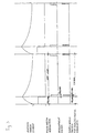
- FIG. 3 represents the operating principle of the system, in accordance with the concept of this invention.
- Figure 4 shows the electric circuit diagram, with MOSFET transistors, which control the temperature of the honeycomb structure.
- FIG. 5 shows the circuit used in the experiment for the reaction between Palladium and Hydrogen.
- Figure 6 shows a circuit for measuring flow rates.
- the preferred embodiment of the present invention comprises a substrate consisting a strip of stainless steel foil of 5-20 microns in thickness, shaped accordingly for the kind of application.
- This substrate is excited by means of a pulse width modulation power supply unit and measurements of temperature of the heater itself are performed during its thermal relaxation phase between adjacent pulses.
- Figure 1 shows a composite Fleisch honeycomb structure (1) made according to the concept of present invention.
- This consists of a structure obtained by rolling together two overlapping foils (2), (3), one of which is corrugated to obtain a honeycomb structure.
- One of the two foils is conductive (2) (i.e. made of stainless steel, from 0.01 to 0.05 mm in thickness, preferably 0.02 mm) and features a resistance value (2-3 Ohms with a temperature coefficient of some hundreds of microohms per °C) that makes it suitable for fast heating to the operating temperature by means of hand-held, low-power batteries.
- the other foil is a corrosion-proof insulator (3), capable of withstanding heat overloads up to 120 °C in order to allow thermal disinfection.
- FIG. 2 shows an electrical circuit diagram representing the concept of this invention.
- This circuit is used to heat the Fleisch honeycomb structure shown in figure 1 as well as for other applications. It consists of a microcontroller (4), a bridge (5) with a heating/sensor element (6) on one branch and temperature-invariant resistors (7), (8) & (9) on the other branches, a switch (10) for connecting the power supply to the heating/sensor element (6) for the heating phase, a double switch (11) for supplying power to the bridge (5) for measuring thermal relaxation of the heating/sensor element itself (6) when the heating phase is not active, an instrumentation amplifier (12) for collecting bridge signals, which is then connected to the analog-digital converter (13) incorporated inside the microcontroller (4).
- Figure 3 provides a general description of how the system works.
- the digital power switch is turned on for 150 microseconds, whereas thermal relaxation of the element takes place for the remaining 850 microseconds of the duty cycle.
- the element heats up.
- the temperature trend depends on the voltage and time.
- the time period of 150 microseconds can be increased or decreased depending on whether more or less heat is needed, whereas the 1-millisecond time separation between pulses is maintained constant.
- the measuring phase begins. This consists of one or more measurements during the thermal relaxation. For example purposes, two measurements at the beginning and end of the relaxation phase (fig. 3) have been indicated.
- the microcontroller (4) issues a measurement pulse that is long enough to ensure stabilisation of the operational amplifier (12) for the measuring phase (i.e. 20 microseconds). At this time, the same pulse, delayed by the amplifier stabilisation time (12), is returned to the sample&hold circuit (S/H) of the 10-bit analog-digital converter (13) incorporated inside the microcontroller itself (4).
- the power supply to the bridge is switched off 10 microseconds after the S/H pulse which enabled the acquisition of the bridge amplifier signal. This supply period is kept short compared to the total relaxation time in order to reduce interference in the heating/sensor element.
- FIG. 4 shows the electrical circuit diagram for temperature calibration of the Fleisch honeycomb structure.
- the digital switches are substituted by MOSFET transistors (19), (20).
- the Fleisch power supply works as if it were a switch as shown in fig. 2, whereas bridge power is supplied by means of a second MOSFET.
- a fast diode (21) situated at the top of the bridge facing towards the branch of the Fleisch structure completes the double switch function as it prevents the current from passing through the other branches of the bridge while the Fleisch structure (1) is in operation.
- a second fast diode (22) similar to the first is placed at the top of the bridge facing towards the other branch to ensure the same voltage drop in the two branches while the bridge is in operation.
- the amplifier gain value (23) is programmable. This can be increased when the signal is low and the 10-bit definition of the converter is unable to ensure sufficiently accurate measurements.
- the circuit in figure 5 is used in a calorimeter for the Palladium-Hydrogen interaction experiment. It has a solenoid valve which is used to introduce 200 mbar of hydrogen into the calorimeter.
- the bridge has two opposite branches (27, 28) that are activated with heating times which can differ, so that the bridge can be kept in balance as better clarified further on.
- the circuit shown in figure 6 is similar to that shown in figure 4 except for the reference element (26) which substitutes the temperature-invariant resistor in the bridge branch where the heating/sensor element is located, collects data regarding the fluid temperature and provides an output signal that is already filtered from the influence of temperature.
- the thermal inertia of the conductive sheet (2) is low (it weighs less than 10 grams) and enables fast heating to body temperature.
- Cold-start setting of the instrument can be performed within 30 seconds for a Fleisch No. 4 size structure, and temperature calibration can be stopped immediately after the test, as well as the related power supply, which can be reduced to its new lighter duties.
- the transducer is maintained free from condensed vapor, which is crucial towards rendering the measurement robust to environmental conditions (humidity) and indispensable during intensive testing (exhaled air is saturated with water vapor). In addition, it can be sterilized on the spot by heating it up to 120 °C for a few seconds, or removed for cleaning with disinfectants.
- Previous descriptions referring to the honeycomb filter can also be applied to the fine mesh screen in the same way, the only difference being that in this case there are wires instead of sheets.
- the heating/sensor element has been enclosed in a reactive chamber equipped with inlet/outlet valves enabling either evacuation of the chamber or introduction of the selected gas.
- the sensor element consists of a 5-micron stainless steel foil. For this, taking into account a weight of 8 g/cm 3 and a specific thermal capacity of 0.1 cal/g referring to a unit area of 1 cm 2 , we have a thermal capacity ⁇ 400 ⁇ cal/°C cm 2 .
- the loss of radiation per cm 2 taking into account an emission factor for a polished surface of 4% is 5.67 x 10 -12 x 0.04 x 333 4 ⁇ 27.89 x 10 -4 Wo ⁇ 669.31 ⁇ cal/cm 2 sec
- the heater/sensor temperature (solid-gas phase) is calibrated to 60°C by means of the PWM power supply and adopting a frequency range from 1 to 10 kHz and accepting a ripple less than 1°C around the mean value of 60°C.
- a Palladium-coated (0.1 micron) strip we obtain 0.12 mg/cm 2 weight and 7 microcalories/°C cm 2 thermal capacity.
- the duty cycle of the PWM supply to the Pd coated strip is continuously adjusted in order to maintain the bridge in equilibrium and the power differences between the two PWM supplies provides an immediate indication of the amount of heat exchanged.
Landscapes
- Health & Medical Sciences (AREA)
- Life Sciences & Earth Sciences (AREA)
- Physics & Mathematics (AREA)
- Fluid Mechanics (AREA)
- General Physics & Mathematics (AREA)
- Medical Informatics (AREA)
- Surgery (AREA)
- Biophysics (AREA)
- Pathology (AREA)
- Engineering & Computer Science (AREA)
- Biomedical Technology (AREA)
- Heart & Thoracic Surgery (AREA)
- Physiology (AREA)
- Molecular Biology (AREA)
- Pulmonology (AREA)
- Animal Behavior & Ethology (AREA)
- General Health & Medical Sciences (AREA)
- Public Health (AREA)
- Veterinary Medicine (AREA)
- Investigating Or Analyzing Materials Using Thermal Means (AREA)
- Measuring Volume Flow (AREA)
- Measurement Of The Respiration, Hearing Ability, Form, And Blood Characteristics Of Living Organisms (AREA)
- Heterocyclic Carbon Compounds Containing A Hetero Ring Having Oxygen Or Sulfur (AREA)
- Thermotherapy And Cooling Therapy Devices (AREA)
- Measurement Of Force In General (AREA)
Applications Claiming Priority (3)
| Application Number | Priority Date | Filing Date | Title |
|---|---|---|---|
| IT96PD000004A IT1287889B1 (it) | 1996-01-19 | 1996-01-19 | Dispositivo con piccola capacita' termica per spirometria portabile di precisione e per altre applicazioni |
| ITPD960004 | 1996-01-19 | ||
| PCT/IB1997/000012 WO1997025920A1 (en) | 1996-01-19 | 1997-01-13 | A low thermal capacity device for high precision pocket-size spirometry and other applications |
Publications (2)
| Publication Number | Publication Date |
|---|---|
| EP0959763A1 EP0959763A1 (en) | 1999-12-01 |
| EP0959763B1 true EP0959763B1 (en) | 2003-04-09 |
Family
ID=11391213
Family Applications (1)
| Application Number | Title | Priority Date | Filing Date |
|---|---|---|---|
| EP97900020A Expired - Lifetime EP0959763B1 (en) | 1996-01-19 | 1997-01-13 | A low thermal capacity device for high precision pocket-size spirometry and other applications |
Country Status (11)
| Country | Link |
|---|---|
| US (1) | US6732581B1 (it) |
| EP (1) | EP0959763B1 (it) |
| JP (1) | JP4040680B2 (it) |
| CN (1) | CN1152649C (it) |
| AT (1) | ATE236572T1 (it) |
| AU (1) | AU706045B2 (it) |
| BR (1) | BR9707025A (it) |
| DE (1) | DE69720792T2 (it) |
| ES (1) | ES2196295T3 (it) |
| IT (1) | IT1287889B1 (it) |
| WO (1) | WO1997025920A1 (it) |
Families Citing this family (4)
| Publication number | Priority date | Publication date | Assignee | Title |
|---|---|---|---|---|
| US8460223B2 (en) | 2006-03-15 | 2013-06-11 | Hill-Rom Services Pte. Ltd. | High frequency chest wall oscillation system |
| KR102150579B1 (ko) * | 2014-03-31 | 2020-09-01 | 히타치 긴조쿠 가부시키가이샤 | 열식 질량 유량 측정 방법, 당해 방법을 사용하는 열식 질량 유량계 및 당해 열식 질량 유량계를 사용하는 열식 질량 유량 제어 장치 |
| US10890472B2 (en) * | 2016-08-25 | 2021-01-12 | Honeywell International Inc. | Low power operational methodology for a flow sensor |
| WO2019199389A1 (en) * | 2018-04-10 | 2019-10-17 | Kci Licensing, Inc. | Bridge dressing with fluid management |
Family Cites Families (19)
| Publication number | Priority date | Publication date | Assignee | Title |
|---|---|---|---|---|
| US2947938A (en) * | 1954-04-09 | 1960-08-02 | Victory Engineering Corp | Electrothermal measuring apparatus and method for the calibration thereof |
| US3425277A (en) * | 1966-11-14 | 1969-02-04 | Gen Electric | Electrical thermal flowmeter |
| US3603147A (en) * | 1969-11-05 | 1971-09-07 | Thermo Systems Inc | Pulsed anemometer circuit |
| US3645133A (en) | 1970-04-15 | 1972-02-29 | Metrophysics Inc | Electronic spirometer |
| JPS58501094A (ja) * | 1981-07-13 | 1983-07-07 | バテル メモリアル インステイチユ−ト | 流体中に浸漬された探査子の熱交換と関連する該流体の少なくとも1つの瞬時的パラメ−タを算定する方法及び該方法を実行するための装置 |
| US4433576A (en) * | 1982-09-20 | 1984-02-28 | General Motors Corporation | Mass airflow sensor |
| US4445369A (en) * | 1982-10-27 | 1984-05-01 | General Motors Corporation | Hot film sensor for air flow meter |
| US4691566A (en) * | 1984-12-07 | 1987-09-08 | Aine Harry E | Immersed thermal fluid flow sensor |
| US4576050A (en) * | 1984-08-29 | 1986-03-18 | General Motors Corporation | Thermal diffusion fluid flow sensor |
| JPH07122587B2 (ja) * | 1988-05-16 | 1995-12-25 | 日産自動車株式会社 | 流量センサ |
| JPH0758212B2 (ja) * | 1989-06-28 | 1995-06-21 | 日産自動車株式会社 | 流量センサ |
| US5080165A (en) * | 1989-08-08 | 1992-01-14 | Grumman Aerospace Corporation | Protective tarpaulin |
| HU208734B (en) * | 1990-04-23 | 1993-12-28 | Ibranyi | Fleisch valve gas flowmeter for a respiratory machine |
| US5582628A (en) | 1991-05-29 | 1996-12-10 | Wood; Tony J. | Unit and system for sensing fluid velocity |
| US5277196A (en) | 1992-03-31 | 1994-01-11 | The United States Of America As Represented By The Department Of Health And Human Services | Portable spirometer with improved accuracy |
| US5357967A (en) * | 1993-06-04 | 1994-10-25 | Baxter International Inc. | Method and apparatus for measuring flow using frequency-dispersive techniques |
| US5518002A (en) * | 1993-10-22 | 1996-05-21 | Medtrac Technologies, Inc. | Portable electronic spirometric device |
| DE19520570A1 (de) * | 1995-06-06 | 1996-12-12 | Otto Dipl Ing Hoffer | Anemometer mit minimaler Versorgungsspannung |
| JP4189070B2 (ja) * | 1998-12-07 | 2008-12-03 | 株式会社堀場エステック | マスフローメータの流量検出機構 |
-
1996
- 1996-01-19 IT IT96PD000004A patent/IT1287889B1/it active IP Right Grant
-
1997
- 1997-01-13 AT AT97900020T patent/ATE236572T1/de not_active IP Right Cessation
- 1997-01-13 ES ES97900020T patent/ES2196295T3/es not_active Expired - Lifetime
- 1997-01-13 US US09/101,454 patent/US6732581B1/en not_active Expired - Fee Related
- 1997-01-13 AU AU11686/97A patent/AU706045B2/en not_active Ceased
- 1997-01-13 DE DE69720792T patent/DE69720792T2/de not_active Expired - Fee Related
- 1997-01-13 BR BR9707025A patent/BR9707025A/pt not_active IP Right Cessation
- 1997-01-13 CN CNB97192371XA patent/CN1152649C/zh not_active Expired - Fee Related
- 1997-01-13 EP EP97900020A patent/EP0959763B1/en not_active Expired - Lifetime
- 1997-01-13 WO PCT/IB1997/000012 patent/WO1997025920A1/en not_active Ceased
- 1997-01-13 JP JP52582697A patent/JP4040680B2/ja not_active Expired - Fee Related
Also Published As
| Publication number | Publication date |
|---|---|
| CN1211169A (zh) | 1999-03-17 |
| JP2000515241A (ja) | 2000-11-14 |
| ITPD960004A0 (it) | 1996-01-19 |
| CN1152649C (zh) | 2004-06-09 |
| EP0959763A1 (en) | 1999-12-01 |
| ATE236572T1 (de) | 2003-04-15 |
| WO1997025920A1 (en) | 1997-07-24 |
| AU1168697A (en) | 1997-08-11 |
| DE69720792D1 (de) | 2003-05-15 |
| DE69720792T2 (de) | 2004-02-05 |
| JP4040680B2 (ja) | 2008-01-30 |
| IT1287889B1 (it) | 1998-08-26 |
| AU706045B2 (en) | 1999-06-10 |
| BR9707025A (pt) | 1999-07-20 |
| ES2196295T3 (es) | 2003-12-16 |
| US6732581B1 (en) | 2004-05-11 |
| ITPD960004A1 (it) | 1997-07-19 |
Similar Documents
| Publication | Publication Date | Title |
|---|---|---|
| US5167927A (en) | Monitor for ozone, hydrogen peroxide and other gases in fluids | |
| Graichen et al. | Automatic dew-point temperature sensor | |
| US6468222B1 (en) | Metabolic calorimeter employing respiratory gas analysis | |
| US6899684B2 (en) | Method of respiratory gas analysis using a metabolic calorimeter | |
| US6612306B1 (en) | Respiratory nitric oxide meter | |
| US20140366610A1 (en) | Gas sensor with heater | |
| EP1202667A1 (en) | Metabolic calorimeter employing respiratory gas analysis | |
| JPH10507264A (ja) | 2つの流動ガス流間の示差酸素濃度を測定する方法及び装置 | |
| WO2018081877A9 (en) | Non-invasive photonic sensing for monitoring diabetes | |
| US20140371619A1 (en) | Gas sensor with heater | |
| AU706045B2 (en) | A low thermal capacity device for high precision pocket-size spirometry and other applications | |
| AU2019290617A1 (en) | Inhalation sensor block, exhalation sensor block and system | |
| WO2007080381A1 (en) | Gas sensor | |
| EP1044365B1 (en) | Method and apparatus for measuring selected properties of a fluid of interest using a single heater element | |
| CA2243403C (en) | A low thermal capacity device for high precision pocket-size spirometry and other applications | |
| EP0513309A1 (en) | Hot wire anemometer | |
| McIlroy et al. | Transcutaneous blood gas measurements using a mass spectrometer | |
| Van Putten et al. | Multisensor microsystem for pulmonary function diagnostics | |
| JP2026502954A (ja) | 流体の流量を決定するための熱式流量センサー | |
| MXPA98005772A (en) | Device with small thermal capacity for precision portable spirometry and other applications | |
| EP4494684A1 (en) | Device and method for monitoring a flow of a fluid | |
| Giordani et al. | Fast psychrometers as new SU-8 based microsystems | |
| Toba et al. | Non-invasive measurement system for human respiratory condition and body temperature | |
| Kamon | Instrumentation for work physiology | |
| JPH03189539A (ja) | 水素濃度測定装置 |
Legal Events
| Date | Code | Title | Description |
|---|---|---|---|
| PUAI | Public reference made under article 153(3) epc to a published international application that has entered the european phase |
Free format text: ORIGINAL CODE: 0009012 |
|
| 17P | Request for examination filed |
Effective date: 19980807 |
|
| AK | Designated contracting states |
Kind code of ref document: A1 Designated state(s): AT BE CH DE DK ES FI FR GB GR IE IT LI LU NL PT SE |
|
| AX | Request for extension of the european patent |
Free format text: AL PAYMENT 19980807;LT PAYMENT 19980807;LV PAYMENT 19980807;RO PAYMENT 19980807;SI PAYMENT 19980807 |
|
| GRAG | Despatch of communication of intention to grant |
Free format text: ORIGINAL CODE: EPIDOS AGRA |
|
| 17Q | First examination report despatched |
Effective date: 20010813 |
|
| GRAG | Despatch of communication of intention to grant |
Free format text: ORIGINAL CODE: EPIDOS AGRA |
|
| GRAH | Despatch of communication of intention to grant a patent |
Free format text: ORIGINAL CODE: EPIDOS IGRA |
|
| GRAH | Despatch of communication of intention to grant a patent |
Free format text: ORIGINAL CODE: EPIDOS IGRA |
|
| GRAH | Despatch of communication of intention to grant a patent |
Free format text: ORIGINAL CODE: EPIDOS IGRA |
|
| GRAA | (expected) grant |
Free format text: ORIGINAL CODE: 0009210 |
|
| AK | Designated contracting states |
Designated state(s): AT BE CH DE DK ES FI FR GB GR IE IT LI LU NL PT SE |
|
| AX | Request for extension of the european patent |
Extension state: AL LT LV RO SI |
|
| PG25 | Lapsed in a contracting state [announced via postgrant information from national office to epo] |
Ref country code: FI Free format text: LAPSE BECAUSE OF FAILURE TO SUBMIT A TRANSLATION OF THE DESCRIPTION OR TO PAY THE FEE WITHIN THE PRESCRIBED TIME-LIMIT Effective date: 20030409 Ref country code: BE Free format text: LAPSE BECAUSE OF FAILURE TO SUBMIT A TRANSLATION OF THE DESCRIPTION OR TO PAY THE FEE WITHIN THE PRESCRIBED TIME-LIMIT Effective date: 20030409 |
|
| REG | Reference to a national code |
Ref country code: GB Ref legal event code: FG4D |
|
| REG | Reference to a national code |
Ref country code: CH Ref legal event code: EP |
|
| REG | Reference to a national code |
Ref country code: IE Ref legal event code: FG4D |
|
| PG25 | Lapsed in a contracting state [announced via postgrant information from national office to epo] |
Ref country code: SE Free format text: LAPSE BECAUSE OF FAILURE TO SUBMIT A TRANSLATION OF THE DESCRIPTION OR TO PAY THE FEE WITHIN THE PRESCRIBED TIME-LIMIT Effective date: 20030709 Ref country code: PT Free format text: LAPSE BECAUSE OF FAILURE TO SUBMIT A TRANSLATION OF THE DESCRIPTION OR TO PAY THE FEE WITHIN THE PRESCRIBED TIME-LIMIT Effective date: 20030709 Ref country code: GR Free format text: LAPSE BECAUSE OF FAILURE TO SUBMIT A TRANSLATION OF THE DESCRIPTION OR TO PAY THE FEE WITHIN THE PRESCRIBED TIME-LIMIT Effective date: 20030709 Ref country code: DK Free format text: LAPSE BECAUSE OF FAILURE TO SUBMIT A TRANSLATION OF THE DESCRIPTION OR TO PAY THE FEE WITHIN THE PRESCRIBED TIME-LIMIT Effective date: 20030709 |
|
| REG | Reference to a national code |
Ref country code: CH Ref legal event code: NV Representative=s name: ABREMA AGENCE BREVETS ET MARQUES GANGUILLET & HUMP |
|
| LTIE | Lt: invalidation of european patent or patent extension |
Effective date: 20030409 |
|
| REG | Reference to a national code |
Ref country code: ES Ref legal event code: FG2A Ref document number: 2196295 Country of ref document: ES Kind code of ref document: T3 |
|
| PG25 | Lapsed in a contracting state [announced via postgrant information from national office to epo] |
Ref country code: LU Free format text: LAPSE BECAUSE OF NON-PAYMENT OF DUE FEES Effective date: 20040113 |
|
| ET | Fr: translation filed | ||
| PLBE | No opposition filed within time limit |
Free format text: ORIGINAL CODE: 0009261 |
|
| STAA | Information on the status of an ep patent application or granted ep patent |
Free format text: STATUS: NO OPPOSITION FILED WITHIN TIME LIMIT |
|
| 26N | No opposition filed |
Effective date: 20040112 |
|
| REG | Reference to a national code |
Ref country code: FR Ref legal event code: ST |
|
| PG25 | Lapsed in a contracting state [announced via postgrant information from national office to epo] |
Ref country code: IE Free format text: LAPSE BECAUSE OF NON-PAYMENT OF DUE FEES Effective date: 20060113 |
|
| REG | Reference to a national code |
Ref country code: FR Ref legal event code: RN |
|
| REG | Reference to a national code |
Ref country code: FR Ref legal event code: FC |
|
| REG | Reference to a national code |
Ref country code: IE Ref legal event code: MM4A |
|
| REG | Reference to a national code |
Ref country code: IE Ref legal event code: NE4A |
|
| PGFP | Annual fee paid to national office [announced via postgrant information from national office to epo] |
Ref country code: ES Payment date: 20080130 Year of fee payment: 12 Ref country code: CH Payment date: 20080131 Year of fee payment: 12 |
|
| PGFP | Annual fee paid to national office [announced via postgrant information from national office to epo] |
Ref country code: NL Payment date: 20080131 Year of fee payment: 12 Ref country code: GB Payment date: 20080109 Year of fee payment: 12 Ref country code: DE Payment date: 20080206 Year of fee payment: 12 |
|
| PGFP | Annual fee paid to national office [announced via postgrant information from national office to epo] |
Ref country code: AT Payment date: 20080131 Year of fee payment: 12 |
|
| PGFP | Annual fee paid to national office [announced via postgrant information from national office to epo] |
Ref country code: FR Payment date: 20080131 Year of fee payment: 12 |
|
| REG | Reference to a national code |
Ref country code: IE Ref legal event code: NF4A Effective date: 20080811 |
|
| PGFP | Annual fee paid to national office [announced via postgrant information from national office to epo] |
Ref country code: IE Payment date: 20080619 Year of fee payment: 12 |
|
| PGRI | Patent reinstated in contracting state [announced from national office to epo] |
Ref country code: IE Effective date: 20080811 |
|
| REG | Reference to a national code |
Ref country code: CH Ref legal event code: PL |
|
| GBPC | Gb: european patent ceased through non-payment of renewal fee |
Effective date: 20090113 |
|
| NLV4 | Nl: lapsed or anulled due to non-payment of the annual fee |
Effective date: 20090801 |
|
| REG | Reference to a national code |
Ref country code: IE Ref legal event code: MM4A |
|
| PG25 | Lapsed in a contracting state [announced via postgrant information from national office to epo] |
Ref country code: LI Free format text: LAPSE BECAUSE OF NON-PAYMENT OF DUE FEES Effective date: 20090131 Ref country code: DE Free format text: LAPSE BECAUSE OF NON-PAYMENT OF DUE FEES Effective date: 20090801 Ref country code: CH Free format text: LAPSE BECAUSE OF NON-PAYMENT OF DUE FEES Effective date: 20090131 Ref country code: AT Free format text: LAPSE BECAUSE OF NON-PAYMENT OF DUE FEES Effective date: 20090113 |
|
| PG25 | Lapsed in a contracting state [announced via postgrant information from national office to epo] |
Ref country code: NL Free format text: LAPSE BECAUSE OF NON-PAYMENT OF DUE FEES Effective date: 20090801 Ref country code: GB Free format text: LAPSE BECAUSE OF NON-PAYMENT OF DUE FEES Effective date: 20090113 |
|
| PG25 | Lapsed in a contracting state [announced via postgrant information from national office to epo] |
Ref country code: IE Free format text: LAPSE BECAUSE OF NON-PAYMENT OF DUE FEES Effective date: 20090113 |
|
| REG | Reference to a national code |
Ref country code: ES Ref legal event code: FD2A Effective date: 20090114 |
|
| PG25 | Lapsed in a contracting state [announced via postgrant information from national office to epo] |
Ref country code: ES Free format text: LAPSE BECAUSE OF NON-PAYMENT OF DUE FEES Effective date: 20090114 |
|
| REG | Reference to a national code |
Ref country code: FR Ref legal event code: ST Effective date: 20110131 |
|
| PG25 | Lapsed in a contracting state [announced via postgrant information from national office to epo] |
Ref country code: IT Free format text: LAPSE BECAUSE OF NON-PAYMENT OF DUE FEES Effective date: 20100113 |
|
| PG25 | Lapsed in a contracting state [announced via postgrant information from national office to epo] |
Ref country code: FR Free format text: LAPSE BECAUSE OF NON-PAYMENT OF DUE FEES Effective date: 20090202 |
|
| PGRI | Patent reinstated in contracting state [announced from national office to epo] |
Ref country code: IT Effective date: 20110616 |
|
| PGFP | Annual fee paid to national office [announced via postgrant information from national office to epo] |
Ref country code: IT Payment date: 20120125 Year of fee payment: 16 |
|
| PG25 | Lapsed in a contracting state [announced via postgrant information from national office to epo] |
Ref country code: IT Free format text: LAPSE BECAUSE OF NON-PAYMENT OF DUE FEES Effective date: 20130113 |