EP0960231B2 - Wäschebehandlungsgerät mit einem auf der trommelwelle angeordneten antriebsmotor - Google Patents
Wäschebehandlungsgerät mit einem auf der trommelwelle angeordneten antriebsmotor Download PDFInfo
- Publication number
- EP0960231B2 EP0960231B2 EP98906957A EP98906957A EP0960231B2 EP 0960231 B2 EP0960231 B2 EP 0960231B2 EP 98906957 A EP98906957 A EP 98906957A EP 98906957 A EP98906957 A EP 98906957A EP 0960231 B2 EP0960231 B2 EP 0960231B2
- Authority
- EP
- European Patent Office
- Prior art keywords
- motor
- winding
- laundry treating
- stator
- current
- Prior art date
- Legal status (The legal status is an assumption and is not a legal conclusion. Google has not performed a legal analysis and makes no representation as to the accuracy of the status listed.)
- Expired - Lifetime
Links
- 238000004804 winding Methods 0.000 claims abstract description 61
- 238000005406 washing Methods 0.000 claims abstract description 35
- 230000001360 synchronised effect Effects 0.000 claims abstract description 19
- 230000003313 weakening effect Effects 0.000 claims description 17
- 238000013178 mathematical model Methods 0.000 claims description 8
- 230000001419 dependent effect Effects 0.000 claims description 6
- 230000001105 regulatory effect Effects 0.000 claims description 3
- 238000011156 evaluation Methods 0.000 claims description 2
- 238000013461 design Methods 0.000 abstract description 9
- 238000011161 development Methods 0.000 abstract description 2
- 238000005265 energy consumption Methods 0.000 abstract description 2
- RYGMFSIKBFXOCR-UHFFFAOYSA-N Copper Chemical compound [Cu] RYGMFSIKBFXOCR-UHFFFAOYSA-N 0.000 description 6
- 229910052802 copper Inorganic materials 0.000 description 6
- 239000010949 copper Substances 0.000 description 6
- 239000004065 semiconductor Substances 0.000 description 5
- XEEYBQQBJWHFJM-UHFFFAOYSA-N Iron Chemical compound [Fe] XEEYBQQBJWHFJM-UHFFFAOYSA-N 0.000 description 4
- 238000012937 correction Methods 0.000 description 4
- 238000001514 detection method Methods 0.000 description 4
- 238000010586 diagram Methods 0.000 description 4
- 230000004907 flux Effects 0.000 description 3
- 238000009987 spinning Methods 0.000 description 3
- 240000006829 Ficus sundaica Species 0.000 description 2
- 239000010261 arctane Substances 0.000 description 2
- 230000033228 biological regulation Effects 0.000 description 2
- 230000002349 favourable effect Effects 0.000 description 2
- 229910052742 iron Inorganic materials 0.000 description 2
- 238000003475 lamination Methods 0.000 description 2
- 238000007620 mathematical function Methods 0.000 description 2
- 238000000034 method Methods 0.000 description 2
- 238000005096 rolling process Methods 0.000 description 2
- 230000035945 sensitivity Effects 0.000 description 2
- 241000555745 Sciuridae Species 0.000 description 1
- XAGFODPZIPBFFR-UHFFFAOYSA-N aluminium Chemical compound [Al] XAGFODPZIPBFFR-UHFFFAOYSA-N 0.000 description 1
- 229910052782 aluminium Inorganic materials 0.000 description 1
- 230000015572 biosynthetic process Effects 0.000 description 1
- 238000004364 calculation method Methods 0.000 description 1
- 239000003990 capacitor Substances 0.000 description 1
- 239000002131 composite material Substances 0.000 description 1
- 238000010276 construction Methods 0.000 description 1
- 230000001276 controlling effect Effects 0.000 description 1
- 230000018109 developmental process Effects 0.000 description 1
- 230000008030 elimination Effects 0.000 description 1
- 238000003379 elimination reaction Methods 0.000 description 1
- 230000005284 excitation Effects 0.000 description 1
- 238000010438 heat treatment Methods 0.000 description 1
- 230000006698 induction Effects 0.000 description 1
- 238000002347 injection Methods 0.000 description 1
- 239000007924 injection Substances 0.000 description 1
- 230000003287 optical effect Effects 0.000 description 1
- 230000002441 reversible effect Effects 0.000 description 1
- 238000004904 shortening Methods 0.000 description 1
- 239000000243 solution Substances 0.000 description 1
- 239000000725 suspension Substances 0.000 description 1
- 230000002123 temporal effect Effects 0.000 description 1
Images


Classifications
-
- D—TEXTILES; PAPER
- D06—TREATMENT OF TEXTILES OR THE LIKE; LAUNDERING; FLEXIBLE MATERIALS NOT OTHERWISE PROVIDED FOR
- D06F—LAUNDERING, DRYING, IRONING, PRESSING OR FOLDING TEXTILE ARTICLES
- D06F37/00—Details specific to washing machines covered by groups D06F21/00 - D06F25/00
- D06F37/30—Driving arrangements
- D06F37/304—Arrangements or adaptations of electric motors
Definitions
- the invention relates to a laundry treatment equipment such as washing machine, dryer or washer-dryer with a rotatably mounted drum with at least approximately horizontal axis of rotation, and with a arranged on the drum shaft drive motor in the form of a permanent magnet synchronous motor whose stator is provided with a winding which is energized by an inverter wherein the winding is designed as a single-pole winding and the number of stator poles and the magnetic poles is unequal.
- a washing machine is out of the WO-A-98/00902 known.
- An engine according to the preamble of claim 1 is known from DE 43 41 832 A1 known. There, a drum directly driving motor is described, which is designed as a converter-fed synchronous motor. Further information is not provided on the engine type.
- washing machines with directly driving motors which are constructed as external rotor motors ( DE 44 14 768 A1 . DE 43 35 966 A1 . EP 413 915 A1 . EP 629 735 A2 ).
- the rotor can be manufactured as a deep-drawn part, as a plastic bell or in a composite construction.
- the solution is advantageous as a deep-drawn part, since in this case the iron simultaneously forms the magnetic inference.
- this design is also a typical version of fan motors.
- stator winding can be designed either as a conventional three-phase winding with a winding step over a plurality of stator teeth or as a single-pole winding with winding around a stator tooth.
- the current application takes place in this type of motor with power semiconductors. In this case, depending on the rotor position, the individual
- Strings of the stator winding is energized by an inverter, so that the exciter field rotates with the motor.
- a current that is used for torque formation the third strand remains energized.
- the temporal current course in the individual strands is block or trapezoidal. As a result, occur when switching on and off of the individual windings high rates of change of current, which generate noise on the engine. In laundry treatment appliances, which are partly placed in living rooms (kitchen, bathroom), such noises are undesirable.
- Hall sensors For electronically commutated DC motors, Hall sensors, magnetic sensors or optical sensors are used to sense the rotor position.
- the attachment of such sensors and the associated signal lines is associated with additional costs.
- sensors and cables are prone to failure.
- Another disadvantage is that in such self-commutated permanent magnet motors operation with field weakening is not readily possible.
- the large torque and speed spreads between washing and spinning operation required in washing machines normally cause large spreads in the motor current. Therefore, reversible or tapped windings must be installed, or the motor winding and power semiconductors must be sized for the largest possible current.
- Sinusoidally energized and regulated synchronous motors are already known as servo drives via an inverter. They are used where exact positioning is required.
- the stator winding is designed as a classic three-phase winding, and the number of poles of rotor and stator are identical.
- the three-phase winding is characterized by current and known winding techniques, but has the disadvantage that the volume of copper, especially in the winding heads is very large, which increases the Fertiguniety and increases the depth of the engine. The latter would reduce the drum volume in washing machines with a given case depth.
- servo drives for controlled operation require very accurate and expensive sensors to detect the rotor position
- the single-pole winding of the copper insert is lower than in a classic three-phase winding, in particular the copper volume of the winding heads is much lower. As a result, the entire drive is smaller and more compact. Due to the smaller copper volume higher efficiencies can be achieved with the same motor size due to lower copper losses.
- a control device which adjusts the output voltage of the frequency converter by a control such that adjusts a minimum sinusoidal current depending on the load torque.
- Sinusoidal currents cause a very quiet motor running and a reduction of the losses caused by current harmonics. This is the case in particular if the output voltage is set in the form of a sinusoidal pulse width modulation.
- the torque-dependent current regulation guarantees optimum efficiency in every load point.
- the number of magnetic poles differs characteristically from the number of stator poles.
- a ratio of rotor poles to stator poles of 2 to 3 or of 4 to 3 is favorable. Only in these two cases does the vectorial addition of the voltages of a strand induced in the individual pole windings give a maximum and an optimum of efficiency.
- stator poles With a pole ratio of 4 to 3, the use of about 30 stator poles is favorable in order to cover the required speed range of 0 to 2000 1 / min.
- the selected number of poles ensures a safe start in externally controlled operation, a low torque ripple and a large speed spread.
- control device for controlling the motor current is based on a mathematical model of the motor and if the energization of the winding strands takes place while dispensing with rotor position sensors. Since the motor current and the voltage at the motor can be detected in the frequency converter itself, no sensors are required on the motor.
- a calibration of the mathematical model can take place if necessary or continuously.
- the motor-specific parameters such as winding resistance, motor inductance and induced voltage constant can be determined by means of the already existing current sensors and the microprocessor control in the frequency converter and the mathematical model can be adapted on the basis of the measured values.
- the main advantage of the present invention formed laundry treatment device results from the ability to dimension the number of turns of the stator windings such that the amount of induced voltage or the Polradschreib for high speeds is greater than the maximum output voltage of the frequency converter.
- Such a winding design enables a field weakening operation of the synchronous motor in the higher speed range.
- the advantage of this winding design is a significant reduction of the motor current in the washing mode. It can be chosen such that the motor can be operated in the washing and spinning with the same power. Due to the lower motor current smaller and less expensive power semiconductors can therefore be used. In addition, the losses in the power semiconductors are reduced, whereby the overall efficiency of motor and power electronics is higher than comparable drives with the same copper use.
- Collectorless DC motors can be operated only with great difficulty with field weakening, since then changed the position of the rotor position sensor or the commutation times would have to be moved mathematically. In servo drives a field weakening operation for the aforementioned reasons is not known.
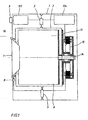
- the washing machine shown has a housing (1) in which a tub (2) to springs (3) is suspended swinging. To damp the vibrations, it is supported against the bottom of the housing (1) by friction dampers (5).
- a drum (6) for receiving laundry (not shown) is rotatably mounted in a known manner.
- Drum (6), tub (2) and the housing front wall (1a) have corresponding openings through which the laundry can be filled in the drum (6).
- the openings can be closed by a door (7) arranged on the housing front wall (1a).
- the locking of the door (7) by an electromagnetic closure device (8).
- the door lock is shown only schematically in the drawing.
- an electromagnetic closure device (8) itself is from the above DE-OS 16 10 247 or from the DE 34 23 083 C2 is well known and will therefore not be described in detail.
- a control panel (not shown) is arranged, in which a rotary selector switch (9) is used to select washing programs.
- the wash programs are known to include a wash and a subsequent rinse during which the laundry is spun several times.
- the washing speed is in household washing machines between 20 and 60 min-1, the spin speed should be as high as possible, especially at the last spin to the end of the rinse cycle. It is limited by the capacity of the oscillating system tub (2) - suspension (3; 5) drive motor (10) drum (6) upwards, the limits are currently at about 1600 min-1.
- FIG. 2 shows a partial section through the rear portion of a tub (2), a drum (6) and its drive motor (10).
- an edge projection (2a) which is formed by the jacket (2b) of the tub (2) and a folded edge of its bottom (2c)
- In the center of this bearing cross (11) is a Lümabe (12), in the two radial rolling bearings (13a, b) are used. These rolling bearings (13a, b) in turn serve to rotatably receive a drive shaft (14) which is non-rotatably connected to the drum base (6a).
- the rear end (14a) of the drive shaft (14) protrudes from the position hub (12). It is attached to a trained as an external rotor permanent magnet rotor (15) and thus drives the drum (6) directly.
- the stator (16) of the drive motor (10) is attached to the bearing cross (11).
- FIG. 4 shows the lamination of a single stator lamination (17a).
- the individual sheets (17a) For attachment of the laminated stator core (17) to the bearing cross, the individual sheets (17a) have fastening eyes, which are arranged on the inner circumferential surface and provided with through-holes (19). Through these holes (19) fixing screws (not shown) out and screwed into threaded holes (26) on the bearing cross (11).
- the bores (26) are arranged concentrically to the bearing hub (12). Their free ends have bearing surfaces (20) for an end face of the laminated stator core (17).
- the centering of the laminated stator core (17) takes place via radially formed stiffening ribs (21).
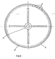
- the rotor (15) consists of a cup-shaped deep-drawn part or an aluminum injection molded part (15a) with a hollow cylinder section (15b) which contains an annular iron yoke (22) and the permanent magnets (23) mounted thereon as rotor poles (see also FIG. 5 ). Furthermore, the rotor (15) has a hub (24) which is connected to the free end (14a) of the drive shaft (14) by a screw bolt (25) and a serration (not shown) form-fitting and thus rotationally fixed.
- the drive motor is designed as a permanent magnet-excited three-phase synchronous motor.
- a three-strand Einzelpolwicklung (Zahnbewicklung) is housed, the strands in a Star connection (s. Fig. 5 . 6 ) are connected.
- the windings of the teeth (27) of a strand are connected in series.
- the drive motor is thus constructed as a modular permanent magnet machine.
- the pole ratio of rotor poles (23) to stator poles (27) is 4 to 3 at a number of 30 stator poles (27).
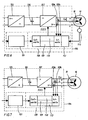
- FIG. 6 shows a block diagram of the structure of the controlled drive with three-phase synchronous motor (10).
- the speed of the motor (10) is dependent on the with the rotary selector switch (9, s. Fig. 1 )) set as a target value of the program control (101) of the washing machine.
- the program control (101) of the washing machine To influence the engine speed, both the frequency of voltage and current and the amount of voltage in the stator windings (18) must be adjusted.
- the motor current is additionally set as a function of the load torque. For this purpose, at least two phase currents I 1 and I 2 are measured with current sensors (103 a, b).
- the mains voltage is converted into a DC voltage via a rectifier (105) and smoothed via a DC link capacitor (106).
- the DC voltage is converted by a three-phase inverter (107), which is connected on the output side to the stator winding (18). Since the intermediate circuit voltage is constant, the voltage at the motor (10) is adjusted via a pulse width modulation.
- the rms value of the voltage can be changed over the pulse width.
- a pulse pattern is selected by which sinusoidal currents are formed in the stator winding (18) of the motor (10). One therefore speaks of a sinusoidal pulse width modulation.
- the inverter (107) is assigned a microprocessor control unit (108) in which a controller (109) and a valve controller (110) are integrated.
- the calculation of the control signals for the transistors of the inverter (107) takes place on the basis of the respective rotor position in order to set the optimum orientation and strength of the rotary field at all times and thus to ensure a sufficient torque on the rotor (15).
- resolvers or analog Hall sensors (111) can be used. Hall sensors (111) are to be preferred because of their low price. In both cases, they are absolute measuring systems which provide accurate information about the absolute position of the rotor (15) with respect to the stator (16) immediately after switching on.
- Such a correction can be effected by storing the analogue output signals of both Hall sensors (111) in a correction device (112) integrated in the microprocessor control (108) during a rotor revolution, and then determining the mean value and maximum and minimum from the stored values , If the average value is known, then an offset can be corrected, while the sensitivity and the temperature drift can be corrected on the basis of maximum and minimum.
- a temperature influence on the remanent induction of the magnets (23) need not be taken into account, since in this case the output signals of both Hall sensors (111) are changed in the same way and in the same size.
- FIG. 6 shows a block diagram of the structure of a control in which can be dispensed with sensors for rotor position detection.
- the rotor position must be calculated by the microprocessor controller (108). This is done on the basis of a mathematical model (113) of the motor (10) stored in the controller, in which the characteristic motor parameters such as winding resistance, motor inductance and induced voltage must be known.
- the motor currents (I 1 , I 2 ) and the motor voltage U_ w are continuously vectorially, ie detected by magnitude and phase, the currents are measured with the sensors and the voltage is known due to the generated by the valve driver (110) pulse pattern.
- the respective operating point of the motor (10) can be determined accurately and the motor (10) can be operated with the minimum current required for the load torque. Since the detection of the motor current and the voltage at the motor (10) in the frequency converter (104) itself can be done, no further sensors on the motor (10) are required.
- an adjustment of the parameters of the mathematical model (113) takes place either as required or continuously.
- Such a calibration may be required if the motor-specific parameters (winding resistance, motor inductance and induced voltage) change during operation due to heating of the motor (10).
- the winding resistance and induced voltage are strongly temperature-dependent quantities.
- the machine Since the machine is operated as a separately driven synchronous motor (10), it is important that the output frequency of the frequency converter (104) during startup of the motor (10) is low. Typical are turn-on frequencies from 0.1 to 1 Hz. This ensures, in conjunction with the high number of poles of the motor (10), even under load a safe and smooth start.
- the number of turns of the stator winding (18) is dimensioned such that at higher speeds, the Polradschreib and the induced voltage of the synchronous motor (10) are higher than the output voltage or the DC link voltage of the frequency converter (104).
- This design allows operation with field weakening at higher speeds.
- the field weakening allows the motor (10) to operate at two operating points at different speeds and at different moments, e.g. Washing and spinning operation to operate with about the same motor current.
- weakening of the field generated by the permanent magnets (23) of the rotor (15) in the air gap is to be understood as weakening of the field by a field having a corresponding strength and phase position generated in the stator (16).
- the pole wheel voltage and the motor current are not in phase, but the phase current is ahead of the pole wheel voltage.
- the angle between stator flux and rotor field becomes greater than 90 ° (electric) in case of field weakening.
- the current has, in addition to the force-forming component in the transverse axis, a negative stator longitudinal current component which is opposite to the rotor field.
- the strand current can be vectorially decomposed into a force-forming and a field-forming component, wherein the force-forming component is in phase with the Polradbeginn and the field-forming component is opposite to the rotor field and this weakens.
- the current-forming component of the current in the transverse axis and the stator longitudinal current component can be adjusted separately from one another with the aid of the current sensors 103a, b, which detect the phase current in at least two phases.
- the drive can also be operated in the field weakening range with minimal power and optimum efficiency.
- a sense and control of the motor current is advantageous in operation with field weakening, since too large a negative stator longitudinal component, the magnets can be irreversibly weakened by the field generated by the stator flooding field.
- the rotor position or the position of the rotor field is calculated with the aid of the measured phase currents and with the mathematical model (113) of the motor (10).
- the rotor position can therefore only be determined as long as the motor (10) is energized.
- the specified by the frequency converter (104) rotating field is continuously reduced in frequency and amplitude until the standstill is reached. If the winding strands of the motor (10) also at standstill, at least partially, energized and the rotor (15) thereby held in position, the next start-up can take place immediately and smoothly in the predetermined direction of rotation.
- the spout can also be unguided or unenergized.
- the drive described also allows reversing without or with only a short reversing pause. This is not readily possible in washing machines which have a drive belt as an intermediate drive. In these washing machines usually universal motors are used as a drive, which expire unregulated or unbraked. This happens after switching off the engine to a coasting or swinging out of the laundry drum. In order to avoid increased wear and noise of the drive belt, wait until the engine has been switched off before switching off the engine, until the washing drum has certainly reached standstill. These downtimes on washing machines with drive belt are typically 2 to 4 seconds. Due to the elimination of these usual and necessary breaks in the reversing result in the direct drive described here shortening of the washing time.
- a further advantageous embodiment of a laundry treatment appliance has a device for evaluating the voltage induced by the rotor (15) during the outflow. Based on this tension can be closed to the current speed. As long as the motor (10) rotates, a voltage is induced in the stator winding (18) of the motor (10). Height and frequency are proportional to the rotor speed. The induced voltage can be used to sense the drum rotation. In a washing machine with an electromagnetically or electromechanically locked door, the induced voltage can be used to operate the shutter (8). As a result, a state-dependent, secure locking of the door (7) is possible in a simple manner without the use of additional speed sensors. Such an application is generally possible in washing machines with permanent magnet rotors and is therefore not limited to the embodiment of the invention.
Landscapes
- Engineering & Computer Science (AREA)
- Textile Engineering (AREA)
- Control Of Motors That Do Not Use Commutators (AREA)
- Control Of Washing Machine And Dryer (AREA)
- Control Of Ac Motors In General (AREA)
- Control Of Multiple Motors (AREA)
- Main Body Construction Of Washing Machines And Laundry Dryers (AREA)
- Treatment Of Fiber Materials (AREA)
- Rolls And Other Rotary Bodies (AREA)
- Permanent Magnet Type Synchronous Machine (AREA)
- Connection Of Motors, Electrical Generators, Mechanical Devices, And The Like (AREA)
Description
- Die Erfindung betrifft ein Wäschebehandlungsgeräte wie Waschmaschine, Wäschetrockner oder Waschtrockner mit einer drehbar gelagerten Trommel mit mindestens annähernd horizontaler Drehachse, und mit einem auf der Trommelwelle angeordneten Antriebsmotor in Form eines permanentmagneterregten Synchronmotors, dessen Stator mit einer Wicklung versehen ist, welche durch einen Umrichter bestromt wird, wobei die Wicklung als Einzelpolwicklung ausgeführt ist und die Anzahl der Statorpole und der Magnetpole ungleich ist. Eine solche Waschmaschine ist aus der
WO-A-98/00902 - Aus der
DE 38 19 651 A1 ist bereits eine Waschmaschine bekannt, bei der ohne Verwendung des üblichen Zwischentriebs (Antriebsriemen, Riemenscheibe) die Wäschetrommel direkt angetrieben wird. Bei diesen Antrieben bildet der Rotor das Drehbewegungsübertragungsteil zur Trommel der Waschmaschine. In derDE 38 19 651 A1 wird vorgeschlagen, einen Asynchronmotor mit einem Käfigläufer zu verwenden. Ein solcher Motor zeichnet sich durch einen relativ geräuscharmen Lauf aus, er besitzt jedoch den Nachteil, daß unter den gegebenen Randbedingungen wie z. B. großer Luftspalt und hochpolige Ausführung bei Asynchronmaschinen gute Wirkungsgrade nicht möglich sind. Gerade bei einem häufig betriebenen Haushaltgerät besteht jedoch der Wunsch nach einer umweltfreundlichen, d. h. energiesparenden Betriebsweise. - Ein Motor gemäß Oberbegriff des Anspruchs 1 ist aus der
DE 43 41 832 A1 bekannt. Dort ist ein die Trommel direkt antreibender Motor beschrieben, der als umrichtergespeister Synchronmotor ausgeführt ist. Weitere Angaben sind zur Motorart nicht gemacht. - Es sind weiterhin Waschmaschinen mit direkt antreibenden Motoren bekannt, die als Außenläufermotoren aufgebaut sind (
DE 44 14 768 A1 ,DE 43 35 966 A1 ,EP 413 915 A1 EP 629 735 A2 - Bei den oben genannten Direktantrieben für Waschmaschinen, insbesondere bei der
WO-A-98/00902 - Stränge der Statorwicklung von einem Wechselrichter bestromt, so daß das Erregerfeld mit dem Motor umläuft. In einer dreisträngigen Erregerwicklung fließt bei dieser Ansteuerung des Motors immer nur in zwei Strängen ein Strom, der zur Momentenbildung dient, wobei der dritte Strang unbestromt bleibt. Der zeitliche Stromverlauf in den einzelnen Strängen ist block- oder trapezförmig. Dadurch treten beim Ein- und Ausschalten der einzelnen Wicklungen hohe Stromänderungsgeschwindigkeiten auf, die Geräusche am Motor erzeugen. Bei Wäschebehandlungsgeräten, die zum Teil in Wohnräumen (Küche, Bad) aufgestellt werden, sind solche Geräusche unerwünscht.
- Bei elektronisch kommutierten Gleichstrommotoren, werden zur Sensierung der Rotorlage Hallsensoren, Magnetgeber oder optische Sensoren verwendet. Das Anbringen solcher Sensoren und der dazugehörenden Signalleitungen ist mit zusätzlichen Kosten verbunden. Außerdem sind Sensoren und Leitungen störanfällig. Ein weiterer Nachteil besteht darin, daß bei solchen selbstgeführten permanentmagneterregten Motoren ein Betrieb mit Feldschwächung nicht ohne weiteres möglich ist. Die bei Waschmaschinen erforderliche große Momenten- und Drehzahlspreizungen zwischen Wasch- und Schleuderbetrieb bewirken normalerweise große Spreizungen des Motorstroms. Deshalb müssen umschaltbare oder angezapfte Wicklungen installiert werden oder die Motorwicklung und die Leistungshalbleiter müssen für den größtmöglichen Strom dimensioniert werden.
- Über einen Umrichter sinusförmig bestromte und geregelte Synchronmotoren sind bereits als Servoantriebe bekannt. Sie werden dort eingesetzt, wo ein genaues Positionieren erforderlich ist. Bei bekannten Servoantrieben ist die Statorwicklung als klassische Drehstromwicklung ausgeführt, und die Polzahl von Rotor und Stator sind identisch. Die Drehstromwicklung zeichnet sich zwar durch gängige und bekannte Wickeltechniken aus, besitzt jedoch den Nachteil, daß das Kupfervolumen insbesondere in den Wickelköpfen sehr groß ist, was die Fertigunskosten erhöht und die Bautiefe des Motors vergrößert. Letzteres würde bei Waschmaschinen mit vorgegebener Gehäusetiefe das Trommelvolumen verringem. Außerdem benötigen Servoantriebe für einen geregelten Betrieb sehr genaue und teure Sensoren zur Erkennung der Rotorlage
- Ein weiterer Nachteil aller vorgenannten permanentmagneterregten Motoren besteht darin, daß sie keine Feldschwächung kennen, da der magnetische Fluß des Motors im wesentlichen vom Feld der Dauermagnete abhängt und somit konstant ist. Für Waschmaschinenantriebe sind solche Motoren deshalb eher ungeeignet, da eine große Momenten- und Drehzahlspreizung zwischen dem Waschbetrieb und dem Schleuderbetrieb eine große Spreizung des Motorstroms zur Folge hätte. Die Motorwicklung und die Leistungshalbleiter des Frequenzumrichters müßten deshalb für den größten Strom dimensioniert werden und wären sehr teuer. Alternativ dazu könnte eine Wicklungsanzapfung verwendet werden, wobei jedoch zusätzliche Leitungen vom Motor zur Elektronik geführt werden müssen. Außerdem werden teure Umschaltrelais notwendig.
- Der Erfindung stellt sich somit das Problem, bei einer Wäschebehandlungsmaschine der eingangs genannten Art den Motor in puncto Energieverbrauch, Geräuschentwicklung und Kosten zu optimieren. Erfindungsgemäß wird dieses Problem durch ein Wäschebehandlungsgerät mit den im Patentanspruch 1 angegebenen Merkmalen gelöst. Vorteilhafte Ausgestaltungen und Weiterbildungen der Erfindung ergeben sich aus den nachfolgenden Unteransprüchen.
- Im Gegensatz zu bisher bekannten Direktantrieben für Waschmaschinen mit kollektorlosen Gleichstrommotoren werden bei dem hier beschriebenen Antriebskonzept alle drei Wicklungsstränge der dreiphasigen Erregerwicklung kontinuierlich bestromt, wobei die Frequenz des Erregerfeldes von der Elektronik vorgegeben wird. Der Motor wird in diesem Fall als fremdgeführter Synchronmotor betrieben. Dieses Verfahren garantiert die geringste Geräuschentwicklung in Verbindung mit einem permanentmagneterregten Synchronmotor.
- Durch die Verwendung der Einzelpolwicklung ist der Kupfereinsatz geringer als bei einer klassischen Drehstromwicklung, insbesondere das Kupfervolumen der Wickelköpfe ist deutlich geringer. Hierdurch wird der gesamte Antrieb kleiner und kompakter. Durch das geringere Kupfervolumen können bei gleicher Motorgröße aufgrund geringerer Kupferverluste höhere Wirkungsgrade erreicht werden.
- Es ist vorteilhaft, den Rotor als Außenläufer auszubilden, hierdurch lassen sich die kompaktesten Bauformen erzielen, weil der drehmomentbildende Luftspaltradius nahe am Außenradius liegt.
- Es ist weiterhin vorteilhaft, eine Steuervorrichtung einzusetzen, welche die Ausgangsspannung des Frequenzumrichters durch eine Regelung derart einstellt, daß sich in Abhängigkeit vom Lastmoment ein minimaler sinusförmiger Strom einstellt. Sinusförmige Ströme bewirken einen sehr leisen Motorlauf und eine Reduzierung der durch Stromoberwellen hervorgerufenen Verluste. Dies ist insbesondere der Fall, wenn die Ausgangsspannung in Form einer sinusbewerteten Pulsweitenmodulation eingestellt ist. Weiterhin gewährleistet die momentenabhängige Stromregelung in jedem Lastpunkt einen optimalen Wirkungsgrad.
- Bei Synchronmotoren mit Einzelpolwicklung weicht die Anzahl der Magnetpole in charakteristischer Weise von der Zahl der Statorpole ab. Bei einer dreisträngigen Auslegung und einer kontinuierlichen Bestromung bzw. einer Drehdurchflutung der Statorwicklung ist ein Verhältnis von Rotorpolen zu Statorpolen von 2 zu 3 oder von 4 zu 3 günstig. Nur in diesen beiden Fällen ergibt die vektorielle Addition der in den einzelnen Polwicklungen induzierten Spannungen eines Stranges ein Maximum und ein Optimum an Wirkungsgrad.
- Bei einem Polverhältnis von 4 zu 3 ist die Verwendung von etwa 30 Statorpolen günstig, um den geforderten Drehzahlbereich von 0 bis 2000 1/min zu überdecken. Die gewählte Polzahl gewährleistet einen sicheren Anlauf bei fremdgeführten Betrieb, eine geringe Momentenwelligkeit und eine große Drehzahlspreizung.
- Daneben ist es vorteilhaft, wenn der Steuervorrichtung zur Regelung des Motorstroms ein mathematisches Modell des Motors zugrundeliegt und wenn die Bestromung der Wicklungsstränge unter Verzicht auf Rotorlagegeber erfolgt. Da die Erfassung des Motorstroms und der Spannung am Motor im Frequenzumrichter selbst erfolgen kann, sind keine Sensoren am Motor erforderlich.
- In einer vorteilhaften Ausführung einer sensorlosen Regelung kann bei Bedarf oder kontinuierlich eine Kalibrierung des mathematischen Modells erfolgen. Die motorspezifischen Parameter wie Wicklungswiderstand, Motorinduktivität und Konstante der induzierten Spannung können mithilfe der ohnehin vorhandenen Stromsensoren und der Mikroprozessor-Steuerung im Frequenzumrichter ermittelt und das mathematischen Modell anhand der gemessenen Werte angepaßt werden.
- Der wesentliche Vorteil des erfindungsgemäß ausgebildeten Wäschebehandlungsgeräts ergibt sich aus der Möglichkeit, die Windungszahl der Statorwicklungen derart zu dimensionieren, daß der Betrag der induzierten Spannung bzw. der Polradspannung für hohe Drehzahlen größer als die maximale Ausgangsspannung des Frequenzumrichters ist. Eine solche Wicklungsauslegung ermöglicht einen Feldschwächungsbetrieb des Synchronmotors im höheren Drehzahlbereich. Der Vorteil dieser Wicklungsauslegung ist eine deutliche Reduzierung des Motorstromes im Waschbetrieb. Sie kann derart gewählt sein, daß der Motor im Wasch- und Schleuderbetrieb mit dem gleichen Strom betrieben werden kann. Aufgrund des geringeren Motorstroms können deswegen kleinere und kostengünstigere Leistungshalbleiter eingesetzt werden. Außerdem werden die Verluste in den Leistungshalbleitern reduziert, wodurch der Gesamtwirkungsgrad von Motor und Leistungselektronik höher ist als bei vergleichbaren Antrieben mit gleichem Kupfereinsatz. Um eine Feldschwächung auch bei Verwendung einer Regelung mit Rotorlagegebem zu ermöglichen, ist es vorteilhaft, auf deren Auswertung bei höheren Drehzahlen zu verzichten. Bei höheren Drehzahlen treten bei Waschmaschinen keine großen oder kurzzeitigen Lastschwankungen auf, so daß eine Regelung des Motorstromes nicht unbedingt erforderlich ist. Der Motor wird in diesem Fall fremdgeführt betrieben, wobei Spannung und Frequenz vom Umrichter ohne Rücksicht auf die Lage des Rotorfeldes vorgegeben werden. Der Motorstrom stellt sich dann in Abhängigkeit vom Lastmoment in Grenzen von selbst ein. Um eine Überlastung und ein außer Tritt fallen des Motors zu verhindern, reicht es aus die Höhe des Motorstromes in Abhängigkeit von der Drehfeldfrequenz zu überwachen.
- Weiterhin lassen sich durch eine Feldschwächung auch mit hochpoligen permanenterregten Synchronmotoren gute Wirkungsgrade bei hohen Drehzahlen erzielen, da die Ummagnetisierungsverluste in Folge der Feldschwächung verringert werden.
- Kollektorlose Gleichstrommmotoren können nur sehr aufwendig mit Feldschwächung betrieben werden, da dann die Position der Rotorlagegeber verändert oder die Kommutierungszeitpunkte rechnerisch verschoben werden müßten. Bei Servoantrieben ist ein Feldschwächebetrieb aus den vorgenannten Gründen nicht bekannt.
- Ein Ausführungsbeispiel der Erfindung ist in den Zeichnungen rein schematisch dargestellt und wird nachfolgend näher beschrieben. Es zeigt:
- Figur 1
- einen Schnitt durch eine erfindungsgemäß aufgebaute Waschmaschine als Schemaskizze
- Figur 2
- einen Teilschnitt durch den hinteren Bereich eines Laugenbehälters (2), einer Trommel (6) und deren Antriebsmotor (10)
- Figur 3
- das Lagerkreuz (11) einer Waschmaschine in perspektivischer Darstellung
- Figur 4
- ein Einzelblech eines Stators (16) des Antriebsmotors (10)
- Figur 5
- einen permanentmagnetischen Rotor (15) in perspektivischer Darstellung
- Figur 6
- ein Blockschaltbild der Struktur des geregelten Antriebs mit Drehstrom-Synchronmotor und Rotorlagegebem
- Figur 7
- ein Blockschaltbild der Struktur des sensorlos geregelten Antriebs mit Drehstrom-Synchronmotor
- Die in
Figur 1 dargestellte Waschmaschine besitzt ein Gehäuse (1), in dem ein Laugenbehälter (2) an Federn (3) schwingbeweglich aufgehängt ist. Zur Dämpfung der Schwingungen wird er gegenüber dem Boden des Gehäus (1) durch Reibungsdämpfer (5) abgestützt. Im Laugenbehälter (2) ist in bekannter Weise eine Trommel (6) zur Aufnahme von Waschgut (nicht dargestellt) drehbar gelagert. Trommel (6), Laugenbehälter (2) und die Gehäusevorderwand (1a) besitzen korrespondierende Öffnungen, durch die das Waschgut in die Trommel (6) eingefüllt werden kann. Die Öffnungen können durch eine an der Gehäusevorderwand (1a) angeordnete Tür (7) verschlossen werden. Die Verriegelung der Tür (7) erfolgt durch eine elektromagnetische Verschlußeinrichtung (8). Die Türverriegelung ist in der Zeichnung lediglich schematisch dargestellt. Der Aufbau und die Funktionsweise einer elektromagnetischen Verschlußeinrichtung (8) selbst ist aus der o. g.DE-OS 16 10 247 oder aus derDE 34 23 083 C2 hinreichend bekannt und wird deshalb nicht näher beschrieben. Im oberen Teil der Gehäusevorderwand (1a) ist ein Bedienfeld (nicht dargestellt) angeordnet, in dem ein Drehwahlschalter (9) zur Anwahl von Waschprogrammen dient. Die Waschprogramme beinhalten bekanntermaßen einen Waschgang und einen sich daran anschließenden Spülgang, in dessen Verlauf die Wäsche mehrmals geschleudert wird. Die Waschdrehzahl beträgt bei Haushaltswaschmaschinen zwischen 20 und 60 min-1, die Schleuderdrehzahl sollte insbesondere beim letzten Schleudern zum Ende des Spülgangs möglichst hoch sein. Sie wird durch die Belastbarkeit des schwingenden Systems Laugenbehälter (2) - Aufhängung (3; 5)-Antriebsmotor (10) -Trommel (6) nach oben begrenzt, die Grenzen liegen derzeit etwa bei 1600 min-1. -
Figur 2 zeigt einen Teilschnitt durch den hinteren Bereich eines Laugenbehälters (2), einer Trommel (6) und deren Antriebsmotor (10). Zur drehbaren Lagerung der Trommel (6) ist an einem Randansatz (2a), der durch den Mantel (2b) des Laugenbehälters (2) und eine Umkantung seines Bodens (2c) gebildet wird, ein inFigur 3 dargestelltes vierarmiges Lagerkreuz (11) befestigt. Im Zentrum dieses Lagerkreuzes (11) befindet sich eine Lagemabe (12), in die zwei Radialwälzlager (13a,b) eingesetzt sind. Diese Wälzlager (13a,b) wiederum dienen zur drehbaren Aufnahme einer Antriebswelle (14), welche drehfest mit dem Trommelboden (6a) verbunden ist. Das hintere Ende (14a) der Antriebswelle (14) ragt aus der Lagemabe (12) heraus. An ihm ist ein als Außenläufer ausgebildeter permantentmagnetischer Rotor (15) befestigt und treibt die Trommel (6) somit direkt an. Der Stator (16) des Antriebsmotors (10) ist am Lagerkreuz (11) befestigt. - Das Statorblechpaket (17) mit den Statorwicklungen (18) ist im wesentlichen ringförmig ausgebildet.
Figur 4 zeigt den Blechschnitt eines einzelnen Statorblechs (17a). Zur Befestigung des Statorblechpakets (17) am Lagerkreuz besitzt die einzelnen Bleche (17a) Befestigungsaugen, die an der inneren Umfangsfläche angeordnet und mit Durchgangsbohrungen (19) versehen sind. Durch diese Bohrungen (19) werden Befestigungsschrauben (nicht dargestellt) geführt und in Gewindebohrungen (26) am Lagerkreuz (11) geschraubt. Die Bohrungen (26) sind konzentrisch zur Lagemabe (12) angeordnet. Ihre freien Enden weisen Auflageflächen (20) für eine Stirnfläche des Statorblechpaketes (17) auf. Die Zentrierung des Statorblechpaketes (17) erfolgt über radial ausgebildete Versteifungsrippen (21). - Der Rotor (15) besteht aus einem topfförmigen Tiefziehteil oder einem Aluminiumspritzgußteil (15a) mit einem Hohlzylinderabschnitt (15b), welcher einen ringförmigen Eisenrückschluß (22) und die darauf befestigten Permanentmagnete (23) als Rotorpole enthält (s. a.
Figur 5 ). Weiterhin weist der Rotor (15) eine Nabe (24) auf, die mit dem freien Ende (14a) der Antriebswelle (14) durch einen Schraubenbolzen (25) und eine Kerbverzahnung (nicht dargestellt) formschlüssig und somit drehfest verbunden ist. - Der Antriebsmotor ist als permanentmagneterregter Drehstrom-Synchronmotor ausgeführt. Im Stator (16) ist eine dreisträngige Einzelpolwicklung (Zahnbewicklung) untergebracht, wobei die Stränge in einer Sternschaltung (s.
Fig. 5 ,6 ) verbunden sind. Die Wicklungen der Zähne (27) eines Stranges sind in Reihe geschaltet. Der Antriebsmotor ist somit als modulare Dauermagnetmaschine aufgebaut. Das Polverhältnis von Rotorpolen (23) zu Statorpolen (27) beträgt 4 zu 3 bei einer Anzahl von 30 Statorpolen (27). -
Figur 6 zeigt als Blockschaltbild die Struktur des geregelten Antriebs mit Drehstrom-Synchronmotor (10). Die Drehzahl des Motors (10) wird in Abhängigkeit von dem mit dem Drehwahlschalter (9, s.Fig. 1 )) eingestellten Programm als Sollwert von der Programmsteuerung (101) der Waschmaschine vorgegeben. Zur Beeinflussung der Motordrehzahl muß sowohl die Frequenz von Spannung und Strom als auch die Höhe der Spannung in den Statorwicklungen (18) verstellt werden. Zur Regelung des Motors (10) wird zusätzlich der Motorstrom in Abhängigkeit vom Lastmoment eingestellt. Hierzu werden mit Stromsensoren (103a, b) mindestens zwei Strangströme I1 und I2 gemessen. - Die Verstellung der vorgenannten Größen erfolgt über den Frequenzumrichter (104). Hierbei wird zunächst die Netzspannung über einen Gleichrichter (105) in eine Gleichspannung umgewandelt und über einen Zwischenkreiskondensator (106) geglättet. Die Gleichspannung wird von einem dreiphasigen Wechselrichter (107) umgewandelt, der ausgangsseitig an die Statorwicklung (18) angeschlossen ist. Da die Zwischenkreisspannung konstant ist, wird die Spannung am Motor (10) über eine Pulsweiten-modulation eingestellt. Der Effektivwert der Spannung läßt sich dabei über die Pulsbreite verändern. Es wird ein Pulsmuster gewählt, durch das sich in der Statorwicklung (18) des Motors (10) sinusförmige Ströme ausbilden. Man spricht deshalb von einer sinusbewerteten Pulsweitenmodulation. Die sinusförmigen Ströme bewirken einen sehr leisen Lauf des Motors (10) und eine Reduzierung der durch Stromoberwellen hervorgerufenen Verluste. Zur Beeinflussung der Pulsmuster ist dem Wechselrichter (107) eine Mikroprozessor-Steuerungrf (108) zugeordnet, in der eine Regelung (109) und eine Ventilansteuerung (110) integriert ist.
- Die Berechnung der Steuersignale für die Transistoren des Wechselrichters (107) erfolgt auf der Grundlage der jeweiligen Rotorlage, um jederzeit die optimale Ausrichtung und Stärke des Drehfeldes einzustellen und damit ein ausreichendes Moment am Rotor (15) zu gewährleisten. Wegen der sinusförmigen Bestromung des Synchronmotors (10) und der momentenabhängigen Stromregelung ist eine kontinuierliche und genaue Rotorlageerkennung erforderlich. Hierzu können Resolver oder analoge Hallsensoren (111) eingesetzt werden. Hallsensoren (111) ist wegen ihrer Preisgünstigkeit der Vorzug zu geben. In beiden Fällen handelt es sich um absolute Meßsysteme, die bereits unmittelbar nach dem Einschalten eine genaue Information über die absolute Lage des Rotors (15) in Bezug auf den Stator (16) liefern. Bei Verwendung von zwei analogen Hallsensoren (111) werden diese mit Hilfe der Rotormagneten zwei gegeneinander um 90° phasenverschobene Signale erzeugen. Mit diesen beiden Signalen läßt sich mit Hilfe der mathematischen Funktion
β= arctan(a/b)
der Rotorwinkel bestimmen. - Bei Einsatz von analogen Hallsensoren (111) ist deren Selbstkalibrierung sinnvoll, da aufgrund von Exemplarstreuungen wie z. B. Empfindlichkeit, Offset, Temperaturdrift usw. die analogen Ausgangssignale verschiedener Hallsensoren (111) in einem konstanten magnetischen Feld nicht unbedingt identisch sind. Für eine genaue Rotorlageerkennung muß daher eine Korrektur der Ausgangssignale erfolgen. Ziel dieser Korrektur ist es, daß die eingesetzten Hallsensoren (111) in einem konstanten magnetischen Feld die gleichen Ausgangssignale liefern. Eine solche Korrektur kann dadurch erfolgen, daß in einer in der Mikroprozessor-Steuerung (108) integrierten Korrekturvorrichtung (112) während einer Rotorumdrehung die analogen Ausgangssignale beider Hallsensoren (111) gespeichert werden und anschließend aus den gespeicherten Werten der Mittelwert sowie Maximum und Minimum ermittelt werden. Ist der Mittelwert bekannt, so läßt sich ein Offset korrigieren, während anhand von Maximum und Minimum die Empfindlichkeit und die Temperaturdrift korrigiert werden können. Ein Temperatureinfluß auf die Remanenzinduktion der Magnete (23) braucht nicht berücksichtig zu werden, da in diesem Fall die Ausgangssignale beider Hallsensoren (111) in gleicher Weise und in gleicher Größe verändert werden. Wird der Rotorwinkel mit Hilfe der mathematischen Funktion
β = arctan(a/b)
berechnet, so bleibt der Quotient (a/b) bei Änderung des Magnetfeldes in Abhängigkeit von der Temperatur konstant. -
Figur 6 zeigt ein Blockschaltbild der Struktur einer Regelung bei der auf Sensoren zur Rotorlageerkennung verzichtet werden kann. Bei einer sensorlosen Regelung des Synchronmotors (10) mit kontinuierlicher, insbesondere mit sinusförmiger Bestromung muß die Rotorpostion durch die Mikroprozessor-Steuerung (108) berechnet werden. Dies erfolgt auf der Grundlage eines in der Steuerung abgelegten mathematischen Modells (113) des Motors (10), bei dem die charakteristischen Motorparameter wie Wicklungswiderstand, Motorinduktivität und induzierte Spannung bekannt sein müssen. Die Motorströme (I1,I2) und die Motorspannung U_w werden kontinuierlich vektoriell, d. h. nach Betrag und Phasenlage erfaßt, wobei die Ströme mit den Sensoren gemessen werden und die Spannung aufgrund des von der Ventilansteuerung (110) erzeugten Pulsmusters bekannt ist. Somit läßt sich der jeweilige Betriebspunkt des Motors (10) genau bestimmen und der Motor (10) kann mit dem für das Lastmoment erforderlichen minimalen Strom betrieben werden. Da die Erfassung des Motorstroms und der Spannung am Motor (10) im Frequenzumrichter (104) selbst erfolgen kann, sind keine weiteren Sensoren am Motor (10) erforderlich. - In einer vorteilhaften Ausführung der sensorlosen Regelung erfolgt entweder bedarfsweise oder kontinuierlich eine Anpassung der Parameter des mathematischen Modells (113). Eine solche Kalibrierung kann erforderlich werden, wenn sich die motorspezifischen Parameter (Wicklungswiderstand, Motorinduktivität und induzierte Spannung) durch Erwärmung des Motors (10) im Betrieb verändern. Insbesondere der Wicklungswiderstand und induzierte Spannung sind stark temperaturabhängige Größen. Durch eine kurzzeitige Bestromung der Statorwicklung (18) durch den Frequenzumrichter (104) mit Gleichstrom, vorteilhafterweise während der Reversierpausen im Waschbetrieb, läßt sich sowohl der augenblickliche Wicklungswiderstand (und damit auch die Temperatur des Motors) als auch die Motorinduktivität ermitteln, wenn die Spannung am Motor (10) bekannt ist und der Strom über die Sensoren (103a, b) im Frequenzumrichter (104) gemessen wird.
- Der Wicklungswiderstand R ergibt sich aus Beziehung R = U/I und die Induktivität L aus der Zeitkonstanten T = L/R, wobei der Strom kontinuierlich erfasst werden muß, um die Zeitkonstante T zu ermitteln.
- Da die Maschine als fremdgeführter Synchronmotor (10) betrieben wird, ist es wichtig, daß die Ausgangsfrequenz des Frequenzumrichters (104) beim Anlauf des Motors (10) niedrig ist. Typisch sind Einschalt-Frequenzen von 0,1 bis 1 Hz. Dies gewährleistet in Verbindung mit der hohen Polzahl des Motors (10) auch unter Last einen sicheren und ruckfreien Anlauf.
- Die Windungszahl der Statorwicklung (18) ist derart bemessen, daß bei höheren Drehzahlen die Polradspannung und die induzierte Spannung des Synchronmotors (10) höher sind als die Ausgangsspannung oder die Zwischenkreisspannung des Frequenzumrichters (104). Diese Auslegung ermöglicht einen Betrieb mit Feldschwächung bei höheren Drehzahlen. Die Feldschwächung ermöglicht den Motor (10) in zwei Betriebspunkten mit unterschiedlichen Drehzahlen und unterschiedlichen Momenten, wie z.B. Wasch- und Schleuderbetrieb, mit etwa dem gleichem Motorstrom zu betreiben.
- Unter Feldschwächung ist in diesem Fall eine Schwächung des von den Permanentmagneten (23) des Rotors (15) erzeugten Feldes im Luftspalt durch ein im Stator (16) erzeugtes Feld mit entsprechender Stärke und Phasenlage zu verstehen. Bei Feldschwächung sind Polradspannung und Motorstrom nicht in Phase, sondem der Strangstrom eilt der Polradspannung voraus. Der Winkel zwischen Ständerdurchflutung und Läuferfeld wird bei Feldschwächung größer als 90° (elektrisch). Der Strom weist zusätzlich zu der kraftbildenden Komponente in der Querachse eine negative Ständerlängsstromkomponente auf, die dem Läuferfeld entgegengerichtet ist. Der Strangstrom kann vektoriell in eine kraftbildende und eine feldbildende Komponente zerlegt werden, wobei die kraftbildende Komponente in Phase mit der Polradspannung ist und die feldbildende Komponente dem Läuferfeld entgegengerichtet ist und dieses schwächt.
- Im geregelten Betrieb läßt sich mit Hilfe der Stromsensoren (103a, b), die in mindestens zwei Phasen den Strangstrom erfassen, die drehmomentbildende Komponente des Strom in der Querachse und die Ständerlängsstromkomponente getrennt voneinander einstellen. Damit kann der Antrieb auch im Feldschwächbereich mit minimalem Strom und optimalem Wirkungsgrad betrieben werden. Eine Sensierung und Regelung des Motorstroms ist im Betrieb mit Feldschwächung vorteilhaft, da bei einer zu großen negativen Ständerlängsstromkomponente die Magnete durch das von der Ständerdurchflutung erzeugte Feld irreversibel geschwächt werden können.
- Bei einer sensorlosen Regelung wird die Rotorposition bzw. die Lage des Rotorfeldes mit Hilfe der gemessenen Strangströme und mit dem mathematischen Modell (113) des Motors (10) berechnet. Die Rotorlage kann daher nur bestimmt werden, solange der Motor (10) bestromt wird. Bei einer sensorlosen Regelung ist es daher vorteilhaft, den Motor (10) auch während der Auslaufphase von der Waschdrehzahl oder von der Schleuderdrehzahl bis zum Stillstand zu bestromen. Hierbei wird das vom Frequenzumrichter (104) vorgegebene Drehfeld kontinuierlich in Frequenz und Amplitude verringert, bis der Stillstand erreicht ist. Werden die Wicklungsstränge des Motors (10) auch im Stillstand, zumindest teilweise, bestromt und der Rotor (15) dadurch in Position gehalten, so kann der nächste Anlauf sofort und ruckfrei in die vorgegebene Drehrichtung erfolgen. Bei Verwendung von Hallsensoren (111) kann der Auslauf auch ungeführt bzw. auch unbestromt erfolgen.
- Der beschriebene Antrieb ermöglicht weiterhin ein Reversieren ohne oder mit nur geringer Reversierpause. Dies ist bei Waschmaschinen, die einen Antriebsriemen als Zwischentrieb aufweisen, nicht ohne weiteres möglich. Bei diesen Waschmaschinen werden üblicherweise Universalmotoren als Antrieb eingesetzt, die ungeregelt bzw. ungebremst auslaufen. Hierbei kommt es nach dem Abschalten des Motors zu einem Austrudeln oder Auspendeln der Wäschetrommel. Um eine erhöhte Abnutzung und Geräusche des Antriebsriemens zu vermeiden, muß nach Abschalten bis zum Wiedereinschalten des Motors solange gewartet werden, bis die Wäschetrommel mit Sicherheit den Stillstand erreicht hat. Diese Stillstandszeiten bei Waschmaschinen mit Antriebsriemen betragen typisch 2 bis 4 Sekunden. Durch den Entfall dieser bisher üblichen und notwendigen Pausen im Reversierbetrieb ergeben sich bei dem hier beschriebenen Direktantrieb Verkürzungen der Waschdauer.
- Eine weitere vorteilhafte Ausführungsform eines Wäschebehandlungsgeräts besitzt eine Vorrichtung zur Auswertung der vom Rotor (15) während des Auslaufs induzierten Spannung. Anhand dieser Spannung kann auf die momentane Drehzahl geschlossen werden. Solange der Motor (10) dreht, wird in der Statorwicklung (18) des Motors (10) eine Spannung induziert. Höhe und Frequenz verhalten sich proportional zur Rotordrehzahl. Die induzierte Spannung kann zur Sensierung der Trommeldrehung genutzt werden. Bei einer Waschmaschine mit einer elektromagnetisch oder elektromechanisch verriegelten Tür kann die induzierte Spannung zum Betrieb der Verschlußeinrichtung (8) verwendet werden. Hierdurch ist in einfacher Weise ohne Verwendung zusätzlicher Drehzahlsensoren eine zustandsabhängige, sichere Verriegelung der Tür (7) möglich. Eine solche Anwendung ist allgemein bei Waschmaschinen mit permanentmagneterregten Rotoren möglich und beschränkt sich deshalb nicht auf die erfindungsgemäße Ausführungsform.
Claims (14)
- Wäschebehandlungsgerät wie Waschmaschine, Wäschetrockner oder Waschtrockner mit einer drehbar gelagerten Trommel (6) mit mindestens annähernd horizontaler Drehachse, und mit einem auf der Trommelwelle angeordneten Antriebsmotor (10), in Form eines permanentmagneterregten Synchronmotors (10), dessen Stator (16) mit einer Wicklung (18) versehen ist, welche durch einen Umrichter bestromt wird, wobei die Wicklung (18) als Einzelpolwicklung ausgeführt ist und die Anzahl der Statorpole (27) und der Magnetpole (23) ungleich ist,
dadurch gekennzeichnet,
daß als Umrichter ein Frequenzumrichter (104) verwendet wird, dessen Ausgangsspannung derart eingestellt ist, daß sich in allen Wicklungssträngen kontinuierliche Ströme ausbilden. - Wäschebehandlungsgerät nach Anspruch 1,
dadurch gekennzeichnet,
daß der Rotor (15) als Außenläufer ausgebildet ist. - Wäschebehandlungsgerät nach einem der Ansprüche 1 oder 2,
gekennzeichnet durch eine Steuervorrichtung (108), welche die Ausgangsspannung des Frequenzumrichters (104) durch eine Regelung (109) derart einstellt, daß in Abhängigkeit vom Lastmoment ein minimaler sinusförmiger Motorstrom erzeugt wird. - Wäschebehandlungsgerät nach Anspruch 3,
dadurch gekennzeichnet,
daß die Ausgangsspannung in Form einer sinusbewerteten Pulsweitenmodulation eingestellt ist. - Wäschebehandlungsgerät nach Anspruch 4,
dadurch gekennzeichnet,
daß die Statorwicklung (18) als dreisträngige Wicklung ausgeführt ist und daß das Verhältnis von Magnetpolen (23) zu Statorpolen (27) 2/3 oder 4/3 beträgt. - Wäschebehandlungsmaschine nach Anspruch 5,
dadurch gekennzeichnet,
daß die Anzahl der Statorpole ca. 30 beträgt. - Wäschebehandlungsgerät nach einem der Ansprüche 1 bis 6,
dadurch gekennzeichnet,
daß der Steuervorrichtung (108) zur Regelung des Motorstroms ein mathematisches Modell (113) des Motors (10) zugrundeliegt und daß die Bestromung der Wicklungsstränge (18) unter Verzicht auf Rotorpositionssensoren erfolgt. - Wäschebehandlungsgerät nach Anspruch 7,
gekennzeichnet durch Sensoren zur Ermittlung veränderlicher motorspezifischer Parameter wie Wicklungswiderstand, Motorinduktivität und Konstante der induzierten Spannung, wobei durch die gemessenen Werte die entsprechenden Bezugswerte des mathematischen Modells (113) in der Steuervorrichtung (108) korrigierbar sind. - Wäschebehandlungsgerät nach einem der Ansprüche 7 oder 8,
dadurch gekennzeichnet,
daß der Rotor (15) durch einen geführten Auslauf im Waschbetrieb derart positionierbar ist, daß nach seinem Stillstand ein sofortiger Anlauf in entgegengesetzter Richtung möglich ist. - Wäschebehandlungsgerät nach einem der Ansprüche 1 bis 6,
dadurch gekennzeichnet,
daß die Bestromung der Wicklungsstränge unter Verwendung der analogen Ausgangssignale von zwei Hallsensoren (111), wobei diese Ausgangssignale durch eine Korrekturvorrichtung (112) hinsichtlich ihrer zeit- oder zustandsabhängigen Schwankungen kalibriert werden. - Wäschebehandlungsmaschie nach einem der Ansprüche 1 bis 10,
dadurch gekennzeichnet,
daß die Windungszahl der Statorwicklungen (18) derart dimensioniert ist, daß der Betrag der induzierten Spannung bzw. der Polradspannung größer als die maximale Ausgangsspannung des Frequenzumrichters (104) ist. - Wäschebehandlungsmaschine nach einem der Ansprüche 1 bis 11,
dadurch gekennzeichnet,
daß die Bestromung des Motors (10) bei höheren Drehzahlen mit Feldschwächung ohne Auswertung eventuell vorhandener Rotorpositionssensoren (Hallsensoren 111) erfolgt. - Wäschebehandlungsmaschine nach einem der Ansprüche 1 bis 12, gekennzeichnet durch eine Vorrichtung (8) zur Auswertung der vom Rotor (15) induzierten Spannung.
- Wäschebehandlungsmaschine nach Anspruch 13 mit einer elektromagnetisch oder elektromechanisch verriegelten Tür (7),
dadurch gekennzeichnet,
daß die Tür (7) durch die Vorrichtung (8) verschließbar ist.
Applications Claiming Priority (3)
| Application Number | Priority Date | Filing Date | Title |
|---|---|---|---|
| DE19706184 | 1997-02-17 | ||
| DE19706184 | 1997-02-17 | ||
| PCT/EP1998/000902 WO1998036123A2 (de) | 1997-02-17 | 1998-02-17 | Wäschebehandlungsgerät mit einem auf der trommelwelle angeordneten antriebsmotor |
Publications (3)
| Publication Number | Publication Date |
|---|---|
| EP0960231A2 EP0960231A2 (de) | 1999-12-01 |
| EP0960231B1 EP0960231B1 (de) | 2002-05-15 |
| EP0960231B2 true EP0960231B2 (de) | 2012-01-25 |
Family
ID=7820597
Family Applications (1)
| Application Number | Title | Priority Date | Filing Date |
|---|---|---|---|
| EP98906957A Expired - Lifetime EP0960231B2 (de) | 1997-02-17 | 1998-02-17 | Wäschebehandlungsgerät mit einem auf der trommelwelle angeordneten antriebsmotor |
Country Status (8)
| Country | Link |
|---|---|
| US (1) | US6341507B1 (de) |
| EP (1) | EP0960231B2 (de) |
| JP (1) | JP2001511674A (de) |
| KR (1) | KR100436152B1 (de) |
| AT (1) | ATE217655T1 (de) |
| DE (2) | DE19806258A1 (de) |
| ES (1) | ES2176972T3 (de) |
| WO (1) | WO1998036123A2 (de) |
Families Citing this family (46)
| Publication number | Priority date | Publication date | Assignee | Title |
|---|---|---|---|---|
| EP0982425B2 (de) | 1998-08-17 | 2007-08-29 | Miele & Cie. KG | Wäschebehandlungsgerät |
| DE19849594C1 (de) * | 1998-10-27 | 2000-03-30 | Miele & Cie | Waschmaschine oder Waschtrockner |
| KR100539513B1 (ko) * | 1998-12-29 | 2006-02-28 | 엘지전자 주식회사 | 드럼세탁기의 베어링 지지구조 |
| TW470801B (en) * | 1999-03-31 | 2002-01-01 | Toshiba Corp | Drum type washing machine |
| TW472094B (en) * | 1999-05-19 | 2002-01-11 | Toshiba Corp | Rolling drum type washing machine |
| DE29910332U1 (de) * | 1999-06-10 | 2000-10-26 | Struckmeier GmbH Antriebstechnik, 65527 Niedernhausen | Elektrischer Antriebsmotor für Arbeitsmaschinen, insbesondere für Extruder oder Spritzgießmaschinen |
| US6341509B1 (en) * | 1999-09-03 | 2002-01-29 | Kryptonite Corporation | Tie lock assemblage with replaceable lock mechanism |
| DE50002576D1 (de) * | 1999-09-28 | 2003-07-24 | Miele & Cie | Wäschebehandlungsmaschine mit einer fliegend gelagerten Trommel |
| AU782017B2 (en) | 1999-10-18 | 2005-06-30 | Lg Electronics Inc. | A driving unit for a drum type washing machine |
| AU753411B2 (en) | 1999-10-19 | 2002-10-17 | Lg Electronics Inc. | Structure of driving unit in drum type washing machine |
| DE19963703A1 (de) * | 1999-12-29 | 2001-07-05 | Bsh Bosch Siemens Hausgeraete | Antriebsvorrichtung für eine Waschmaschine |
| KR100370010B1 (ko) * | 2000-04-19 | 2003-02-05 | 엘지전자 주식회사 | 드럼세탁기의 구동부 |
| KR100348626B1 (ko) * | 2000-09-28 | 2002-08-13 | 엘지전자주식회사 | 세탁기의 포량감지장치 |
| DE10054947A1 (de) * | 2000-11-06 | 2002-05-08 | Bsh Bosch Siemens Hausgeraete | Verfahren und Vorrichtung zum Behandeln von Wäsche |
| DE10060633A1 (de) * | 2000-12-06 | 2002-06-13 | Bsh Bosch Siemens Hausgeraete | Trommelwaschmaschine |
| DE10064549A1 (de) * | 2000-12-22 | 2002-06-27 | Bsh Bosch Siemens Hausgeraete | Trommelwaschmaschine mit verbesserter Wasch- oder Spülflüssigkeitszufuhr in die Innentrommel |
| TW584688B (en) * | 2001-06-06 | 2004-04-21 | Toshiba Corp | Washing machine |
| JP3651595B2 (ja) * | 2001-12-13 | 2005-05-25 | 株式会社東芝 | 洗濯機のインバータ装置及び洗濯乾燥機のインバータ装置 |
| DE10202252C1 (de) * | 2002-01-21 | 2003-03-20 | Miele & Cie | Verfahren zum Betrieb einer Waschmaschine |
| CN100519892C (zh) * | 2002-03-26 | 2009-07-29 | 阿塞里克有限公司 | 滚筒 |
| DE10254286B4 (de) * | 2002-11-20 | 2007-06-28 | Miele & Cie. Kg | Verfahren zur Herstellung eines als Außenläufer ausggebildeten Rotors für eine permanentmagneterregten Synchronmotor |
| KR100495183B1 (ko) * | 2002-11-28 | 2005-06-14 | 엘지전자 주식회사 | 세탁기의 터브 어셈블리 |
| JP3977762B2 (ja) * | 2003-03-06 | 2007-09-19 | 株式会社東芝 | ドラム式洗濯機 |
| US7471054B2 (en) * | 2003-06-11 | 2008-12-30 | Askoll Holding S.R.L. | Method for detecting unbalanced conditions of a rotating load driven by a synchronous motor and for controlling said motor |
| DE10361405A1 (de) * | 2003-12-29 | 2005-07-28 | BSH Bosch und Siemens Hausgeräte GmbH | Wäschebehandlungsgerät mit einer Steueranordnung zum Betreiben eines elektrischen Motors |
| KR20050089355A (ko) * | 2004-03-04 | 2005-09-08 | 엘지전자 주식회사 | 대용량 드럼세탁기용 비엘디시 모터 |
| DE102004049549A1 (de) * | 2004-03-24 | 2005-10-13 | Diehl Ako Stiftung & Co. Kg | Motor als Direktantrieb und Verfahren zur Montage des Motors |
| DE102004050898B4 (de) * | 2004-10-19 | 2007-04-12 | Siemens Ag | Verfahren und Einrichtung zur Überwachung einer Temperatur eines Lagers einer rotierend umlaufenden Welle |
| DE202005021593U1 (de) | 2005-02-25 | 2008-10-30 | Askoll Holding S.R.L., Povolaro Di Dueville | Struktur eines elektrischen Synchronmotors, insbesondere für Waschmaschinen mit einer rotierenden Trommel, die durch einen Riemenscheibenantrieb mit dem Motor kinematisch gekoppelt ist |
| DE102005048487A1 (de) * | 2005-10-07 | 2007-04-19 | TRüTZSCHLER GMBH & CO. KG | Vorrichtung an einer Spinnereivorbereitungsmaschine, insbes. Karde, Reiniger, Strecke, Kämmmaschine o. dgl., mit mindestens einer elektromotorisch angetriebenen Walze |
| DE102006028201A1 (de) * | 2006-06-20 | 2007-12-27 | Schaeffler Kg | Antrieb für Waschmaschine |
| KR101270538B1 (ko) * | 2006-07-12 | 2013-06-03 | 삼성전자주식회사 | 식기세척기 |
| DE102006045146A1 (de) * | 2006-07-17 | 2008-01-31 | Diehl Ako Stiftung & Co. Kg | Antriebsvorrichtung für eine Waschmaschine |
| ITTO20070843A1 (it) * | 2007-11-23 | 2009-05-24 | Indesit Co Spa | Metodo per rilevare il livello di un liquido di lavaggio all'interno di una macchina di lavaggio, e relativa macchina di lavaggio. |
| DE102008015717A1 (de) * | 2008-03-26 | 2009-10-08 | BSH Bosch und Siemens Hausgeräte GmbH | Schaltungsanordnung zum sensorlosen Betreiben eines Universalmotors eines Hausgeräts und entsprechendes Verfahren |
| DE102008018356A1 (de) * | 2008-04-11 | 2009-10-15 | Diehl Ako Stiftung & Co. Kg | Wäschetrockner |
| DE102008019921A1 (de) * | 2008-04-21 | 2009-10-22 | BSH Bosch und Siemens Hausgeräte GmbH | Hausgerät zur Trocknung von Wäschestücken und Verfahren zum Betreiben eines derartigen Hausgeräts |
| KR20100022145A (ko) * | 2008-08-19 | 2010-03-02 | 삼성전자주식회사 | 세탁기 및 모터의 제어 방법 |
| DE102009033026A1 (de) * | 2009-07-02 | 2011-01-05 | Ebm-Papst Mulfingen Gmbh & Co. Kg | Elektronisch kommutierter Elektromotor |
| US8405268B2 (en) | 2010-02-18 | 2013-03-26 | Nidec Motor Corporation | Stator with monolithic mounting bosses and assembly comprising the same |
| DE202011111030U1 (de) * | 2010-12-22 | 2018-07-05 | Fisher & Paykel Appliances Limited | verbesserte Vorrichtung, Motor oder Stator |
| DE102014203550A1 (de) * | 2014-02-27 | 2015-08-27 | Robert Bosch Gmbh | Elektrisches Antriebssystem |
| DE102014206637A1 (de) * | 2014-04-07 | 2015-10-08 | BSH Hausgeräte GmbH | Verfahren zum Herstellen eines Trommelbodens für eine Wäschetrommel eines Haushaltsgeräts, Wäschetrommel und Haushaltsgerät |
| DE102015101043A1 (de) | 2015-01-26 | 2016-07-28 | Miele & Cie. Kg | Frequenzumrichter für einen elektrischen Motor, mechatronisches System und Waschmaschine |
| BE1029057B1 (de) * | 2021-01-26 | 2022-08-29 | Miele & Cie | Verfahren zum Ansteuern eines mindestens zweiphasigen bürstenlosen Motors |
| CN116964265A (zh) | 2021-05-21 | 2023-10-27 | 三星电子株式会社 | 洗衣机及该洗衣机的控制方法 |
Citations (10)
| Publication number | Priority date | Publication date | Assignee | Title |
|---|---|---|---|---|
| DE1760382A1 (de) † | 1968-05-11 | 1971-06-16 | Licentia Gmbh | Trommelwaschmaschine |
| DE3319121A1 (de) † | 1983-02-02 | 1984-08-02 | General Electric Co., Schenectady, N.Y. | Steueranordnung, verfahren zum betreiben eines elektronisch kommutierten motors und waschvorrichtung |
| DE3436470A1 (de) † | 1984-10-05 | 1986-04-10 | Joachim-Andreas Dipl.-Ing. Wozar (FH), 7300 Esslingen | Einstechwerkzeug |
| DE3819651A1 (de) † | 1988-06-09 | 1989-12-14 | Miele & Cie | Waschmaschine oder waeschetrockner mit einem die waeschetrommel direkt antreibenden antriebsmotor |
| EP0462826A1 (de) † | 1990-06-20 | 1991-12-27 | Matsushita Electric Industrial Co., Ltd. | Bürstenloser Gleichstrommotor |
| US5162709A (en) † | 1989-04-25 | 1992-11-10 | Diesel Kiki Co., Ltd. | Apparatus for controlling blower motor of automobile air-conditioner |
| WO1994005077A1 (en) † | 1992-08-21 | 1994-03-03 | British Technology Group Ltd. | Method of and apparatus for determining a rotor displacement parameter |
| US5448149A (en) † | 1994-06-20 | 1995-09-05 | Texas A&M University | Indirect rotor position sensor for a sinusoidal synchronous reluctance machine |
| NZ328233A (en) † | 1996-07-05 | 1998-01-26 | Toshiba Kk | Washing machine with rotor position detector to control and effect rotation of tub and agitator |
| DE19749391A1 (de) † | 1997-02-18 | 1998-08-27 | Samsung Electronics Co Ltd | Antriebssystem für eine Waschmaschine |
Family Cites Families (21)
| Publication number | Priority date | Publication date | Assignee | Title |
|---|---|---|---|---|
| US3840764A (en) * | 1972-08-25 | 1974-10-08 | M Burger | Drive arrangement for a washing or dry cleaning machine |
| CH664654A5 (fr) * | 1981-12-18 | 1988-03-15 | Cerac Inst Sa | Procede et dispositif pour la commande d'un moteur a courant alternatif sans balai. |
| DE3275393D1 (en) * | 1981-12-18 | 1987-03-12 | Cerac Inst Sa | Washing machine |
| NZ213490A (en) * | 1985-09-16 | 1990-03-27 | Fisher & Paykel | Cyclic motor reversal by forced commutation |
| US4712035A (en) * | 1985-11-12 | 1987-12-08 | General Electric Company | Salient pole core and salient pole electronically commutated motor |
| NZ215389A (en) | 1986-03-06 | 1992-02-25 | Fisher & Paykel | Washing machine: spin tub connected to drive at low water level |
| JPH02142350A (ja) * | 1988-08-03 | 1990-05-31 | Victor Co Of Japan Ltd | 多相直流コア有モータ |
| US4998052A (en) * | 1989-07-28 | 1991-03-05 | General Electric Company | Gearless direct drive switched reluctance motor for laundry application |
| DE3927426B4 (de) * | 1989-08-19 | 2006-02-23 | Ebm-Papst Mulfingen Gmbh & Co. Kg | Antriebseinheit für eine Wäsche-Behandlungsmaschine |
| JP2895942B2 (ja) * | 1990-09-18 | 1999-05-31 | 三洋電機株式会社 | 洗濯機 |
| JPH05344741A (ja) * | 1992-06-10 | 1993-12-24 | Hitachi Ltd | インバータ装置及びこのインバータ装置を備えた空気調和機並びに電気洗濯機それに電気掃除機 |
| GB2295160B (en) * | 1992-08-27 | 1996-10-02 | Gen Electric | Electronic washer control including automatic brake operations |
| JPH06165561A (ja) * | 1992-11-26 | 1994-06-10 | Toshiba Corp | 同期電動機の制御装置 |
| DE4335966C2 (de) | 1993-10-21 | 1998-07-16 | Fhp Motors Gmbh | Antriebsvorrichtung für eine Wasch- oder eine ähnliche Maschine mit einem kollektorlosen Gleichstrommotor |
| DE4341832C2 (de) * | 1993-12-08 | 2001-11-08 | Fhp Motors Gmbh | Waschautomat |
| US5586455A (en) * | 1994-03-30 | 1996-12-24 | Kabushiki Kaisha Toshiba | Float-type clutch for automatic washing machine |
| DE4414768A1 (de) | 1994-04-27 | 1995-11-02 | Mulfingen Elektrobau Ebm | Wäschebehandlungsgerät, wie Waschmaschine oder Wäschetrockner |
| JP2956484B2 (ja) * | 1994-09-01 | 1999-10-04 | 日本ビクター株式会社 | ブラシレスモータ |
| JP2905119B2 (ja) * | 1995-06-30 | 1999-06-14 | 株式会社東芝 | 洗濯機 |
| JPH0947075A (ja) * | 1995-07-28 | 1997-02-14 | Matsushita Electric Ind Co Ltd | ブラシレスモータ |
| TR199802748T2 (xx) * | 1996-07-02 | 1999-03-22 | Domel Elektromotorji In Gospodinjski Aparati, D.O.O. | Bir çamaşır makinası tamburunun doğrudan tahriki için elektronik komütasyonlu motor. |
-
1998
- 1998-02-17 WO PCT/EP1998/000902 patent/WO1998036123A2/de not_active Ceased
- 1998-02-17 US US09/367,378 patent/US6341507B1/en not_active Expired - Lifetime
- 1998-02-17 JP JP53537798A patent/JP2001511674A/ja active Pending
- 1998-02-17 KR KR10-1999-7004953A patent/KR100436152B1/ko not_active Expired - Fee Related
- 1998-02-17 EP EP98906957A patent/EP0960231B2/de not_active Expired - Lifetime
- 1998-02-17 DE DE19806258A patent/DE19806258A1/de not_active Withdrawn
- 1998-02-17 ES ES98906957T patent/ES2176972T3/es not_active Expired - Lifetime
- 1998-02-17 AT AT98906957T patent/ATE217655T1/de active
- 1998-02-17 DE DE59804137T patent/DE59804137D1/de not_active Expired - Lifetime
Patent Citations (10)
| Publication number | Priority date | Publication date | Assignee | Title |
|---|---|---|---|---|
| DE1760382A1 (de) † | 1968-05-11 | 1971-06-16 | Licentia Gmbh | Trommelwaschmaschine |
| DE3319121A1 (de) † | 1983-02-02 | 1984-08-02 | General Electric Co., Schenectady, N.Y. | Steueranordnung, verfahren zum betreiben eines elektronisch kommutierten motors und waschvorrichtung |
| DE3436470A1 (de) † | 1984-10-05 | 1986-04-10 | Joachim-Andreas Dipl.-Ing. Wozar (FH), 7300 Esslingen | Einstechwerkzeug |
| DE3819651A1 (de) † | 1988-06-09 | 1989-12-14 | Miele & Cie | Waschmaschine oder waeschetrockner mit einem die waeschetrommel direkt antreibenden antriebsmotor |
| US5162709A (en) † | 1989-04-25 | 1992-11-10 | Diesel Kiki Co., Ltd. | Apparatus for controlling blower motor of automobile air-conditioner |
| EP0462826A1 (de) † | 1990-06-20 | 1991-12-27 | Matsushita Electric Industrial Co., Ltd. | Bürstenloser Gleichstrommotor |
| WO1994005077A1 (en) † | 1992-08-21 | 1994-03-03 | British Technology Group Ltd. | Method of and apparatus for determining a rotor displacement parameter |
| US5448149A (en) † | 1994-06-20 | 1995-09-05 | Texas A&M University | Indirect rotor position sensor for a sinusoidal synchronous reluctance machine |
| NZ328233A (en) † | 1996-07-05 | 1998-01-26 | Toshiba Kk | Washing machine with rotor position detector to control and effect rotation of tub and agitator |
| DE19749391A1 (de) † | 1997-02-18 | 1998-08-27 | Samsung Electronics Co Ltd | Antriebssystem für eine Waschmaschine |
Non-Patent Citations (8)
| Title |
|---|
| B. MAURICE: "Digitale Steuerung eines Dreiphasen Induktionsmotors", DESIGN UND ELEKTRONIK, vol. 8, 1992, pages 40 - 46 † |
| BELEGE UND SCHRIFTVERKEHR ZUM VERKAUF EINER WASCHMASCHINE DES TYPS FISHER & PAYKEL MW 051 UEBER EBAY † |
| K. HEUMANN, GRUNDLAGEN DER LEISTUNGSELEKTRONIK, 1989 † |
| MESSPROTOKOLL EINER WASCHMASCHINE DES TYPS FISHER & PAYKEL SMART DRIVE 708 † |
| T. JACOBS: "Electronic motor speed control in automatic washing machines", INTERNATIONAL CONFERENCE ON POWER ELECTRONICS, 1974, pages 191 - 197 † |
| UNTERSUCHUNGSBERICHT EINER WASCHMASCHINE DES TYPS FISHER & PAYKEL MW 051 † |
| VERKAUFSBELEGE EINER WASCHMASCHINE DES TYPS FISHER & PAYKEL MW 051 † |
| VERKAUFSPROSPEKT FISHER UND PAYKEL, 1993 † |
Also Published As
| Publication number | Publication date |
|---|---|
| JP2001511674A (ja) | 2001-08-14 |
| EP0960231B1 (de) | 2002-05-15 |
| WO1998036123A3 (de) | 1998-11-19 |
| EP0960231A2 (de) | 1999-12-01 |
| WO1998036123A2 (de) | 1998-08-20 |
| US6341507B1 (en) | 2002-01-29 |
| ATE217655T1 (de) | 2002-06-15 |
| KR100436152B1 (ko) | 2004-06-18 |
| KR20000069295A (ko) | 2000-11-25 |
| DE59804137D1 (de) | 2002-06-20 |
| ES2176972T3 (es) | 2002-12-01 |
| DE19806258A1 (de) | 1998-08-20 |
Similar Documents
| Publication | Publication Date | Title |
|---|---|---|
| EP0960231B2 (de) | Wäschebehandlungsgerät mit einem auf der trommelwelle angeordneten antriebsmotor | |
| DE69422162T2 (de) | Verfahren und Vorrichtung zum Regeln der Drehzahl eines Waschmaschinenmotors | |
| EP1124321B1 (de) | Wechelstrom-Synchronmotor | |
| EP0945973B1 (de) | Vorrichtung zum Steuern eines Einphasen-Synchronmotors | |
| EP2112264B1 (de) | Hausgerät zur Trocknung von Wäschestücken und Verfahren zum Betreiben eines derartigen Hausgeräts | |
| DE102010062918A1 (de) | Haushaltsgerät zur Pflege von Wäschestücken, insbesondere Waschmaschine | |
| DE19820929A1 (de) | Vorrichtung zum Steuern eines Einphasen-Synchronmotors | |
| DE19934668A1 (de) | Elektronisch kommutierbarer Motor | |
| DE4404889A1 (de) | Elektrisches Antriebssystem für ein gleichstrombetriebenes Fahrzeug sowie Verfahren zum Steuern eines gleichstrombetriebenen Antriebs-Elektromotors | |
| EP1554797A1 (de) | Sensorsystem und verfahren zur vektorsteuerung | |
| EP1443635B1 (de) | Verfahren zum Steuern des Zündwinkels und einphasiger wechselstromversorgter Elektromotor | |
| DE3805662A1 (de) | Ringspinnmaschine | |
| DE4404926A1 (de) | Elektrisches Antriebssystem für ein gleichstrombetriebenes Fahrzeug sowie Verfahren zum Steuern eines gleichstrombetriebenen Antriebs-Elektromotors | |
| EP1048774B1 (de) | Verfahren und Vorrichtung zur Detektion von Unwuchten bei einem durch einen bürstenlosen Elektromotor angetriebenen Rotor | |
| DE4017442A1 (de) | Einzelspindelantrieb fuer eine arbeitsstelle einer spinnereimaschine | |
| WO1999010584A1 (de) | Waschmaschine | |
| DE10025016B4 (de) | Wäschebehandlungsgerät mit einem Antriebsmotor in Form eines Direktantriebs | |
| DE69031548T2 (de) | Motor mit einem ständig angeschlossenen Phasenverschiebungskondensator für eine Waschmaschine | |
| EP2328266A1 (de) | Verfahren zum Betreiben eines 2-phasigen oder mehrphasigen elektrischen Motors in einer Waschmaschine, Frequenzumrichter und mechatronisches System. | |
| EP2086094A2 (de) | Permanentmagneterregte elektrische Maschine für ein Hausgerät | |
| DE9407983U1 (de) | Vorrichtung zum Antrieb eines Einphasen-Synchronmotors, insbesondere zum Antrieb eines Pumpenantriebes in einem Haushaltsgerät | |
| WO2009098143A2 (de) | Permanentmagneterregte elektrische maschine für ein hausgerät und schaltungsanordnung mit einer permanentmagneterregten maschine | |
| EP0539617B1 (de) | Unwuchtüberwachung für einen Waschautomaten | |
| AT383916B (de) | Gleichstrommotor mit permanentmagnetischem rotor und elektronischer kommutierschaltung | |
| DE10021067A1 (de) | Elektromotorisch angetriebener Lüfter zum Belüften eines Sensors |
Legal Events
| Date | Code | Title | Description |
|---|---|---|---|
| PUAI | Public reference made under article 153(3) epc to a published international application that has entered the european phase |
Free format text: ORIGINAL CODE: 0009012 |
|
| 17P | Request for examination filed |
Effective date: 19990514 |
|
| AK | Designated contracting states |
Kind code of ref document: A2 Designated state(s): AT BE CH DE DK ES FR GB IT LI NL SE |
|
| GRAG | Despatch of communication of intention to grant |
Free format text: ORIGINAL CODE: EPIDOS AGRA |
|
| GRAG | Despatch of communication of intention to grant |
Free format text: ORIGINAL CODE: EPIDOS AGRA |
|
| GRAH | Despatch of communication of intention to grant a patent |
Free format text: ORIGINAL CODE: EPIDOS IGRA |
|
| 17Q | First examination report despatched |
Effective date: 20010816 |
|
| GRAH | Despatch of communication of intention to grant a patent |
Free format text: ORIGINAL CODE: EPIDOS IGRA |
|
| GRAA | (expected) grant |
Free format text: ORIGINAL CODE: 0009210 |
|
| AK | Designated contracting states |
Kind code of ref document: B1 Designated state(s): AT BE CH DE DK ES FR GB IT LI NL SE |
|
| REF | Corresponds to: |
Ref document number: 217655 Country of ref document: AT Date of ref document: 20020615 Kind code of ref document: T |
|
| REG | Reference to a national code |
Ref country code: GB Ref legal event code: FG4D Free format text: NOT ENGLISH Ref country code: CH Ref legal event code: EP |
|
| REG | Reference to a national code |
Ref country code: CH Ref legal event code: NV Representative=s name: PA ALDO ROEMPLER |
|
| REF | Corresponds to: |
Ref document number: 59804137 Country of ref document: DE Date of ref document: 20020620 |
|
| PG25 | Lapsed in a contracting state [announced via postgrant information from national office to epo] |
Ref country code: DK Free format text: LAPSE BECAUSE OF FAILURE TO SUBMIT A TRANSLATION OF THE DESCRIPTION OR TO PAY THE FEE WITHIN THE PRESCRIBED TIME-LIMIT Effective date: 20020815 |
|
| GBT | Gb: translation of ep patent filed (gb section 77(6)(a)/1977) |
Effective date: 20020819 |
|
| ET | Fr: translation filed | ||
| REG | Reference to a national code |
Ref country code: ES Ref legal event code: FG2A Ref document number: 2176972 Country of ref document: ES Kind code of ref document: T3 |
|
| PLBQ | Unpublished change to opponent data |
Free format text: ORIGINAL CODE: EPIDOS OPPO |
|
| PLBI | Opposition filed |
Free format text: ORIGINAL CODE: 0009260 |
|
| PLBI | Opposition filed |
Free format text: ORIGINAL CODE: 0009260 |
|
| 26 | Opposition filed |
Opponent name: DIEHL STIFTUNG & CO Effective date: 20030131 |
|
| 26 | Opposition filed |
Opponent name: BSH BOSCH UND SIEMENS HAUSGERAETE GMBH Effective date: 20030217 Opponent name: DIEHL STIFTUNG & CO Effective date: 20030131 |
|
| PLBF | Reply of patent proprietor to notice(s) of opposition |
Free format text: ORIGINAL CODE: EPIDOS OBSO |
|
| RAP2 | Party data changed (patent owner data changed or rights of a patent transferred) |
Owner name: MIELE & CIE. KG |
|
| PLAX | Notice of opposition and request to file observation + time limit sent |
Free format text: ORIGINAL CODE: EPIDOSNOBS2 |
|
| NLT2 | Nl: modifications (of names), taken from the european patent patent bulletin |
Owner name: MIELE & CIE. KG |
|
| PLBB | Reply of patent proprietor to notice(s) of opposition received |
Free format text: ORIGINAL CODE: EPIDOSNOBS3 |
|
| PLBQ | Unpublished change to opponent data |
Free format text: ORIGINAL CODE: EPIDOS OPPO |
|
| PLAB | Opposition data, opponent's data or that of the opponent's representative modified |
Free format text: ORIGINAL CODE: 0009299OPPO |
|
| R26 | Opposition filed (corrected) |
Opponent name: BSH BOSCH UND SIEMENS HAUSGERAETE GMBH Effective date: 20030217 Opponent name: DIEHL STIFTUNG & CO. Effective date: 20030131 |
|
| NLR1 | Nl: opposition has been filed with the epo |
Opponent name: BSH BOSCH UND SIEMENS HAUSGERAETE GMBH Opponent name: DIEHL STIFTUNG & CO. |
|
| APBP | Date of receipt of notice of appeal recorded |
Free format text: ORIGINAL CODE: EPIDOSNNOA2O |
|
| APBQ | Date of receipt of statement of grounds of appeal recorded |
Free format text: ORIGINAL CODE: EPIDOSNNOA3O |
|
| APAA | Appeal reference recorded |
Free format text: ORIGINAL CODE: EPIDOS REFN |
|
| APAH | Appeal reference modified |
Free format text: ORIGINAL CODE: EPIDOSCREFNO |
|
| PLAB | Opposition data, opponent's data or that of the opponent's representative modified |
Free format text: ORIGINAL CODE: 0009299OPPO |
|
| APBU | Appeal procedure closed |
Free format text: ORIGINAL CODE: EPIDOSNNOA9O |
|
| REG | Reference to a national code |
Ref country code: GB Ref legal event code: 746 Effective date: 20061019 |
|
| PLAB | Opposition data, opponent's data or that of the opponent's representative modified |
Free format text: ORIGINAL CODE: 0009299OPPO |
|
| PLAB | Opposition data, opponent's data or that of the opponent's representative modified |
Free format text: ORIGINAL CODE: 0009299OPPO |
|
| R26 | Opposition filed (corrected) |
Opponent name: BSH BOSCH UND SIEMENS HAUSGERAETE GMBH Effective date: 20030217 Opponent name: DIEHL STIFTUNG & CO. Effective date: 20030131 |
|
| R26 | Opposition filed (corrected) |
Opponent name: BSH BOSCH UND SIEMENS HAUSGERAETE GMBH Effective date: 20030217 Opponent name: DIEHL STIFTUNG & CO. Effective date: 20030131 |
|
| NLR1 | Nl: opposition has been filed with the epo |
Opponent name: BSH BOSCH UND SIEMENS HAUSGERAETE GMBH Opponent name: DIEHL STIFTUNG & CO. |
|
| NLR1 | Nl: opposition has been filed with the epo |
Opponent name: BSH BOSCH UND SIEMENS HAUSGERAETE GMBH Opponent name: DIEHL STIFTUNG & CO. |
|
| REG | Reference to a national code |
Ref country code: CH Ref legal event code: PCAR Free format text: ALDO ROEMPLER PATENTANWALT;BRENDENWEG 11 POSTFACH 154;9424 RHEINECK (CH) |
|
| PLAY | Examination report in opposition despatched + time limit |
Free format text: ORIGINAL CODE: EPIDOSNORE2 |
|
| PLBP | Opposition withdrawn |
Free format text: ORIGINAL CODE: 0009264 |
|
| PLBC | Reply to examination report in opposition received |
Free format text: ORIGINAL CODE: EPIDOSNORE3 |
|
| PLBP | Opposition withdrawn |
Free format text: ORIGINAL CODE: 0009264 |
|
| PUAH | Patent maintained in amended form |
Free format text: ORIGINAL CODE: 0009272 |
|
| STAA | Information on the status of an ep patent application or granted ep patent |
Free format text: STATUS: PATENT MAINTAINED AS AMENDED |
|
| 27A | Patent maintained in amended form |
Effective date: 20120125 |
|
| AK | Designated contracting states |
Kind code of ref document: B2 Designated state(s): AT BE CH DE DK ES FR GB IT LI NL SE |
|
| REG | Reference to a national code |
Ref country code: DE Ref legal event code: R102 Ref document number: 59804137 Country of ref document: DE |
|
| REG | Reference to a national code |
Ref country code: CH Ref legal event code: AEN Free format text: AUFRECHTERHALTUNG DES PATENTES IN GEAENDERTER FORM |
|
| REG | Reference to a national code |
Ref country code: DE Ref legal event code: R102 Ref document number: 59804137 Country of ref document: DE Effective date: 20120125 |
|
| PGFP | Annual fee paid to national office [announced via postgrant information from national office to epo] |
Ref country code: CH Payment date: 20120221 Year of fee payment: 15 |
|
| REG | Reference to a national code |
Ref country code: NL Ref legal event code: VDEP Effective date: 20120125 |
|
| PGFP | Annual fee paid to national office [announced via postgrant information from national office to epo] |
Ref country code: GB Payment date: 20120222 Year of fee payment: 15 Ref country code: SE Payment date: 20120221 Year of fee payment: 15 Ref country code: BE Payment date: 20120221 Year of fee payment: 15 |
|
| PG25 | Lapsed in a contracting state [announced via postgrant information from national office to epo] |
Ref country code: NL Free format text: LAPSE BECAUSE OF FAILURE TO SUBMIT A TRANSLATION OF THE DESCRIPTION OR TO PAY THE FEE WITHIN THE PRESCRIBED TIME-LIMIT Effective date: 20120125 |
|
| PGFP | Annual fee paid to national office [announced via postgrant information from national office to epo] |
Ref country code: NL Payment date: 20120224 Year of fee payment: 15 |
|
| REG | Reference to a national code |
Ref country code: SE Ref legal event code: NAV |
|
| PGFP | Annual fee paid to national office [announced via postgrant information from national office to epo] |
Ref country code: AT Payment date: 20120220 Year of fee payment: 15 |
|
| PG25 | Lapsed in a contracting state [announced via postgrant information from national office to epo] |
Ref country code: ES Free format text: LAPSE BECAUSE OF FAILURE TO SUBMIT A TRANSLATION OF THE DESCRIPTION OR TO PAY THE FEE WITHIN THE PRESCRIBED TIME-LIMIT Effective date: 20020826 |
|
| PGFP | Annual fee paid to national office [announced via postgrant information from national office to epo] |
Ref country code: ES Payment date: 20120221 Year of fee payment: 15 |
|
| PG25 | Lapsed in a contracting state [announced via postgrant information from national office to epo] |
Ref country code: ES Free format text: LAPSE BECAUSE OF FAILURE TO SUBMIT A TRANSLATION OF THE DESCRIPTION OR TO PAY THE FEE WITHIN THE PRESCRIBED TIME-LIMIT Effective date: 20120506 |
|
| BERE | Be: lapsed |
Owner name: *MIELE & CIE. G.M.B.H. & CO. Effective date: 20130228 |
|
| REG | Reference to a national code |
Ref country code: CH Ref legal event code: PL |
|
| REG | Reference to a national code |
Ref country code: AT Ref legal event code: MM01 Ref document number: 217655 Country of ref document: AT Kind code of ref document: T Effective date: 20130228 |
|
| GBPC | Gb: european patent ceased through non-payment of renewal fee |
Effective date: 20130217 |
|
| PG25 | Lapsed in a contracting state [announced via postgrant information from national office to epo] |
Ref country code: AT Free format text: LAPSE BECAUSE OF NON-PAYMENT OF DUE FEES Effective date: 20130228 Ref country code: CH Free format text: LAPSE BECAUSE OF NON-PAYMENT OF DUE FEES Effective date: 20130228 Ref country code: LI Free format text: LAPSE BECAUSE OF NON-PAYMENT OF DUE FEES Effective date: 20130228 |
|
| PG25 | Lapsed in a contracting state [announced via postgrant information from national office to epo] |
Ref country code: GB Free format text: LAPSE BECAUSE OF NON-PAYMENT OF DUE FEES Effective date: 20130217 Ref country code: BE Free format text: LAPSE BECAUSE OF NON-PAYMENT OF DUE FEES Effective date: 20130228 |
|
| REG | Reference to a national code |
Ref country code: DE Ref legal event code: R081 Ref document number: 59804137 Country of ref document: DE Owner name: DIEHL AKO STIFTUNG & CO. KG, DE Free format text: FORMER OWNER: MIELE & CIE. KG, 33332 GUETERSLOH, DE Effective date: 20140206 |
|
| REG | Reference to a national code |
Ref country code: FR Ref legal event code: TP Owner name: DIEHL AKO STITFTUNG & CO. KG, DE Effective date: 20140304 |
|
| PG25 | Lapsed in a contracting state [announced via postgrant information from national office to epo] |
Ref country code: SE Free format text: LAPSE BECAUSE OF NON-PAYMENT OF DUE FEES Effective date: 20130218 |
|
| REG | Reference to a national code |
Ref country code: FR Ref legal event code: PLFP Year of fee payment: 19 |
|
| REG | Reference to a national code |
Ref country code: FR Ref legal event code: PLFP Year of fee payment: 20 |
|
| PGFP | Annual fee paid to national office [announced via postgrant information from national office to epo] |
Ref country code: FR Payment date: 20170217 Year of fee payment: 20 |
|
| PGFP | Annual fee paid to national office [announced via postgrant information from national office to epo] |
Ref country code: IT Payment date: 20170221 Year of fee payment: 20 |
|
| PGFP | Annual fee paid to national office [announced via postgrant information from national office to epo] |
Ref country code: DE Payment date: 20170420 Year of fee payment: 20 |
|
| REG | Reference to a national code |
Ref country code: DE Ref legal event code: R071 Ref document number: 59804137 Country of ref document: DE |