EP0960231B2 - Appareil de traitement de lessive avec un moteur d'entrainement monte sur l'arbre du tambour - Google Patents
Appareil de traitement de lessive avec un moteur d'entrainement monte sur l'arbre du tambour Download PDFInfo
- Publication number
- EP0960231B2 EP0960231B2 EP98906957A EP98906957A EP0960231B2 EP 0960231 B2 EP0960231 B2 EP 0960231B2 EP 98906957 A EP98906957 A EP 98906957A EP 98906957 A EP98906957 A EP 98906957A EP 0960231 B2 EP0960231 B2 EP 0960231B2
- Authority
- EP
- European Patent Office
- Prior art keywords
- motor
- winding
- laundry treating
- stator
- current
- Prior art date
- Legal status (The legal status is an assumption and is not a legal conclusion. Google has not performed a legal analysis and makes no representation as to the accuracy of the status listed.)
- Expired - Lifetime
Links
- 238000004804 winding Methods 0.000 claims abstract description 61
- 238000005406 washing Methods 0.000 claims abstract description 35
- 230000001360 synchronised effect Effects 0.000 claims abstract description 19
- 230000003313 weakening effect Effects 0.000 claims description 17
- 238000013178 mathematical model Methods 0.000 claims description 8
- 230000001419 dependent effect Effects 0.000 claims description 6
- 230000001105 regulatory effect Effects 0.000 claims description 3
- 238000011156 evaluation Methods 0.000 claims description 2
- 238000013461 design Methods 0.000 abstract description 9
- 238000011161 development Methods 0.000 abstract description 2
- 238000005265 energy consumption Methods 0.000 abstract description 2
- RYGMFSIKBFXOCR-UHFFFAOYSA-N Copper Chemical compound [Cu] RYGMFSIKBFXOCR-UHFFFAOYSA-N 0.000 description 6
- 229910052802 copper Inorganic materials 0.000 description 6
- 239000010949 copper Substances 0.000 description 6
- 239000004065 semiconductor Substances 0.000 description 5
- XEEYBQQBJWHFJM-UHFFFAOYSA-N Iron Chemical compound [Fe] XEEYBQQBJWHFJM-UHFFFAOYSA-N 0.000 description 4
- 238000012937 correction Methods 0.000 description 4
- 238000001514 detection method Methods 0.000 description 4
- 238000010586 diagram Methods 0.000 description 4
- 230000004907 flux Effects 0.000 description 3
- 238000009987 spinning Methods 0.000 description 3
- 240000006829 Ficus sundaica Species 0.000 description 2
- 239000010261 arctane Substances 0.000 description 2
- 230000033228 biological regulation Effects 0.000 description 2
- 230000002349 favourable effect Effects 0.000 description 2
- 229910052742 iron Inorganic materials 0.000 description 2
- 238000003475 lamination Methods 0.000 description 2
- 238000007620 mathematical function Methods 0.000 description 2
- 238000000034 method Methods 0.000 description 2
- 238000005096 rolling process Methods 0.000 description 2
- 230000035945 sensitivity Effects 0.000 description 2
- 241000555745 Sciuridae Species 0.000 description 1
- XAGFODPZIPBFFR-UHFFFAOYSA-N aluminium Chemical compound [Al] XAGFODPZIPBFFR-UHFFFAOYSA-N 0.000 description 1
- 229910052782 aluminium Inorganic materials 0.000 description 1
- 230000015572 biosynthetic process Effects 0.000 description 1
- 238000004364 calculation method Methods 0.000 description 1
- 239000003990 capacitor Substances 0.000 description 1
- 239000002131 composite material Substances 0.000 description 1
- 238000010276 construction Methods 0.000 description 1
- 230000001276 controlling effect Effects 0.000 description 1
- 230000018109 developmental process Effects 0.000 description 1
- 230000008030 elimination Effects 0.000 description 1
- 238000003379 elimination reaction Methods 0.000 description 1
- 230000005284 excitation Effects 0.000 description 1
- 238000010438 heat treatment Methods 0.000 description 1
- 230000006698 induction Effects 0.000 description 1
- 238000002347 injection Methods 0.000 description 1
- 239000007924 injection Substances 0.000 description 1
- 230000003287 optical effect Effects 0.000 description 1
- 230000002441 reversible effect Effects 0.000 description 1
- 238000004904 shortening Methods 0.000 description 1
- 239000000243 solution Substances 0.000 description 1
- 239000000725 suspension Substances 0.000 description 1
- 230000002123 temporal effect Effects 0.000 description 1
Images


Classifications
-
- D—TEXTILES; PAPER
- D06—TREATMENT OF TEXTILES OR THE LIKE; LAUNDERING; FLEXIBLE MATERIALS NOT OTHERWISE PROVIDED FOR
- D06F—LAUNDERING, DRYING, IRONING, PRESSING OR FOLDING TEXTILE ARTICLES
- D06F37/00—Details specific to washing machines covered by groups D06F21/00 - D06F25/00
- D06F37/30—Driving arrangements
- D06F37/304—Arrangements or adaptations of electric motors
Definitions
- the invention relates to a laundry treatment equipment such as washing machine, dryer or washer-dryer with a rotatably mounted drum with at least approximately horizontal axis of rotation, and with a arranged on the drum shaft drive motor in the form of a permanent magnet synchronous motor whose stator is provided with a winding which is energized by an inverter wherein the winding is designed as a single-pole winding and the number of stator poles and the magnetic poles is unequal.
- a washing machine is out of the WO-A-98/00902 known.
- An engine according to the preamble of claim 1 is known from DE 43 41 832 A1 known. There, a drum directly driving motor is described, which is designed as a converter-fed synchronous motor. Further information is not provided on the engine type.
- washing machines with directly driving motors which are constructed as external rotor motors ( DE 44 14 768 A1 . DE 43 35 966 A1 . EP 413 915 A1 . EP 629 735 A2 ).
- the rotor can be manufactured as a deep-drawn part, as a plastic bell or in a composite construction.
- the solution is advantageous as a deep-drawn part, since in this case the iron simultaneously forms the magnetic inference.
- this design is also a typical version of fan motors.
- stator winding can be designed either as a conventional three-phase winding with a winding step over a plurality of stator teeth or as a single-pole winding with winding around a stator tooth.
- the current application takes place in this type of motor with power semiconductors. In this case, depending on the rotor position, the individual
- Strings of the stator winding is energized by an inverter, so that the exciter field rotates with the motor.
- a current that is used for torque formation the third strand remains energized.
- the temporal current course in the individual strands is block or trapezoidal. As a result, occur when switching on and off of the individual windings high rates of change of current, which generate noise on the engine. In laundry treatment appliances, which are partly placed in living rooms (kitchen, bathroom), such noises are undesirable.
- Hall sensors For electronically commutated DC motors, Hall sensors, magnetic sensors or optical sensors are used to sense the rotor position.
- the attachment of such sensors and the associated signal lines is associated with additional costs.
- sensors and cables are prone to failure.
- Another disadvantage is that in such self-commutated permanent magnet motors operation with field weakening is not readily possible.
- the large torque and speed spreads between washing and spinning operation required in washing machines normally cause large spreads in the motor current. Therefore, reversible or tapped windings must be installed, or the motor winding and power semiconductors must be sized for the largest possible current.
- Sinusoidally energized and regulated synchronous motors are already known as servo drives via an inverter. They are used where exact positioning is required.
- the stator winding is designed as a classic three-phase winding, and the number of poles of rotor and stator are identical.
- the three-phase winding is characterized by current and known winding techniques, but has the disadvantage that the volume of copper, especially in the winding heads is very large, which increases the Fertiguniety and increases the depth of the engine. The latter would reduce the drum volume in washing machines with a given case depth.
- servo drives for controlled operation require very accurate and expensive sensors to detect the rotor position
- the single-pole winding of the copper insert is lower than in a classic three-phase winding, in particular the copper volume of the winding heads is much lower. As a result, the entire drive is smaller and more compact. Due to the smaller copper volume higher efficiencies can be achieved with the same motor size due to lower copper losses.
- a control device which adjusts the output voltage of the frequency converter by a control such that adjusts a minimum sinusoidal current depending on the load torque.
- Sinusoidal currents cause a very quiet motor running and a reduction of the losses caused by current harmonics. This is the case in particular if the output voltage is set in the form of a sinusoidal pulse width modulation.
- the torque-dependent current regulation guarantees optimum efficiency in every load point.
- the number of magnetic poles differs characteristically from the number of stator poles.
- a ratio of rotor poles to stator poles of 2 to 3 or of 4 to 3 is favorable. Only in these two cases does the vectorial addition of the voltages of a strand induced in the individual pole windings give a maximum and an optimum of efficiency.
- stator poles With a pole ratio of 4 to 3, the use of about 30 stator poles is favorable in order to cover the required speed range of 0 to 2000 1 / min.
- the selected number of poles ensures a safe start in externally controlled operation, a low torque ripple and a large speed spread.
- control device for controlling the motor current is based on a mathematical model of the motor and if the energization of the winding strands takes place while dispensing with rotor position sensors. Since the motor current and the voltage at the motor can be detected in the frequency converter itself, no sensors are required on the motor.
- a calibration of the mathematical model can take place if necessary or continuously.
- the motor-specific parameters such as winding resistance, motor inductance and induced voltage constant can be determined by means of the already existing current sensors and the microprocessor control in the frequency converter and the mathematical model can be adapted on the basis of the measured values.
- the main advantage of the present invention formed laundry treatment device results from the ability to dimension the number of turns of the stator windings such that the amount of induced voltage or the Polradschreib for high speeds is greater than the maximum output voltage of the frequency converter.
- Such a winding design enables a field weakening operation of the synchronous motor in the higher speed range.
- the advantage of this winding design is a significant reduction of the motor current in the washing mode. It can be chosen such that the motor can be operated in the washing and spinning with the same power. Due to the lower motor current smaller and less expensive power semiconductors can therefore be used. In addition, the losses in the power semiconductors are reduced, whereby the overall efficiency of motor and power electronics is higher than comparable drives with the same copper use.
- Collectorless DC motors can be operated only with great difficulty with field weakening, since then changed the position of the rotor position sensor or the commutation times would have to be moved mathematically. In servo drives a field weakening operation for the aforementioned reasons is not known.
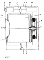
- the washing machine shown has a housing (1) in which a tub (2) to springs (3) is suspended swinging. To damp the vibrations, it is supported against the bottom of the housing (1) by friction dampers (5).
- a drum (6) for receiving laundry (not shown) is rotatably mounted in a known manner.
- Drum (6), tub (2) and the housing front wall (1a) have corresponding openings through which the laundry can be filled in the drum (6).
- the openings can be closed by a door (7) arranged on the housing front wall (1a).
- the locking of the door (7) by an electromagnetic closure device (8).
- the door lock is shown only schematically in the drawing.
- an electromagnetic closure device (8) itself is from the above DE-OS 16 10 247 or from the DE 34 23 083 C2 is well known and will therefore not be described in detail.
- a control panel (not shown) is arranged, in which a rotary selector switch (9) is used to select washing programs.
- the wash programs are known to include a wash and a subsequent rinse during which the laundry is spun several times.
- the washing speed is in household washing machines between 20 and 60 min-1, the spin speed should be as high as possible, especially at the last spin to the end of the rinse cycle. It is limited by the capacity of the oscillating system tub (2) - suspension (3; 5) drive motor (10) drum (6) upwards, the limits are currently at about 1600 min-1.
- FIG. 2 shows a partial section through the rear portion of a tub (2), a drum (6) and its drive motor (10).
- an edge projection (2a) which is formed by the jacket (2b) of the tub (2) and a folded edge of its bottom (2c)
- In the center of this bearing cross (11) is a Lümabe (12), in the two radial rolling bearings (13a, b) are used. These rolling bearings (13a, b) in turn serve to rotatably receive a drive shaft (14) which is non-rotatably connected to the drum base (6a).
- the rear end (14a) of the drive shaft (14) protrudes from the position hub (12). It is attached to a trained as an external rotor permanent magnet rotor (15) and thus drives the drum (6) directly.
- the stator (16) of the drive motor (10) is attached to the bearing cross (11).
- FIG. 4 shows the lamination of a single stator lamination (17a).
- the individual sheets (17a) For attachment of the laminated stator core (17) to the bearing cross, the individual sheets (17a) have fastening eyes, which are arranged on the inner circumferential surface and provided with through-holes (19). Through these holes (19) fixing screws (not shown) out and screwed into threaded holes (26) on the bearing cross (11).
- the bores (26) are arranged concentrically to the bearing hub (12). Their free ends have bearing surfaces (20) for an end face of the laminated stator core (17).
- the centering of the laminated stator core (17) takes place via radially formed stiffening ribs (21).
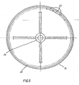
- the rotor (15) consists of a cup-shaped deep-drawn part or an aluminum injection molded part (15a) with a hollow cylinder section (15b) which contains an annular iron yoke (22) and the permanent magnets (23) mounted thereon as rotor poles (see also FIG. 5 ). Furthermore, the rotor (15) has a hub (24) which is connected to the free end (14a) of the drive shaft (14) by a screw bolt (25) and a serration (not shown) form-fitting and thus rotationally fixed.
- the drive motor is designed as a permanent magnet-excited three-phase synchronous motor.
- a three-strand Einzelpolwicklung (Zahnbewicklung) is housed, the strands in a Star connection (s. Fig. 5 . 6 ) are connected.
- the windings of the teeth (27) of a strand are connected in series.
- the drive motor is thus constructed as a modular permanent magnet machine.
- the pole ratio of rotor poles (23) to stator poles (27) is 4 to 3 at a number of 30 stator poles (27).
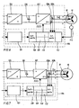
- FIG. 6 shows a block diagram of the structure of the controlled drive with three-phase synchronous motor (10).
- the speed of the motor (10) is dependent on the with the rotary selector switch (9, s. Fig. 1 )) set as a target value of the program control (101) of the washing machine.
- the program control (101) of the washing machine To influence the engine speed, both the frequency of voltage and current and the amount of voltage in the stator windings (18) must be adjusted.
- the motor current is additionally set as a function of the load torque. For this purpose, at least two phase currents I 1 and I 2 are measured with current sensors (103 a, b).
- the mains voltage is converted into a DC voltage via a rectifier (105) and smoothed via a DC link capacitor (106).
- the DC voltage is converted by a three-phase inverter (107), which is connected on the output side to the stator winding (18). Since the intermediate circuit voltage is constant, the voltage at the motor (10) is adjusted via a pulse width modulation.
- the rms value of the voltage can be changed over the pulse width.
- a pulse pattern is selected by which sinusoidal currents are formed in the stator winding (18) of the motor (10). One therefore speaks of a sinusoidal pulse width modulation.
- the inverter (107) is assigned a microprocessor control unit (108) in which a controller (109) and a valve controller (110) are integrated.
- the calculation of the control signals for the transistors of the inverter (107) takes place on the basis of the respective rotor position in order to set the optimum orientation and strength of the rotary field at all times and thus to ensure a sufficient torque on the rotor (15).
- resolvers or analog Hall sensors (111) can be used. Hall sensors (111) are to be preferred because of their low price. In both cases, they are absolute measuring systems which provide accurate information about the absolute position of the rotor (15) with respect to the stator (16) immediately after switching on.
- Such a correction can be effected by storing the analogue output signals of both Hall sensors (111) in a correction device (112) integrated in the microprocessor control (108) during a rotor revolution, and then determining the mean value and maximum and minimum from the stored values , If the average value is known, then an offset can be corrected, while the sensitivity and the temperature drift can be corrected on the basis of maximum and minimum.
- a temperature influence on the remanent induction of the magnets (23) need not be taken into account, since in this case the output signals of both Hall sensors (111) are changed in the same way and in the same size.
- FIG. 6 shows a block diagram of the structure of a control in which can be dispensed with sensors for rotor position detection.
- the rotor position must be calculated by the microprocessor controller (108). This is done on the basis of a mathematical model (113) of the motor (10) stored in the controller, in which the characteristic motor parameters such as winding resistance, motor inductance and induced voltage must be known.
- the motor currents (I 1 , I 2 ) and the motor voltage U_ w are continuously vectorially, ie detected by magnitude and phase, the currents are measured with the sensors and the voltage is known due to the generated by the valve driver (110) pulse pattern.
- the respective operating point of the motor (10) can be determined accurately and the motor (10) can be operated with the minimum current required for the load torque. Since the detection of the motor current and the voltage at the motor (10) in the frequency converter (104) itself can be done, no further sensors on the motor (10) are required.
- an adjustment of the parameters of the mathematical model (113) takes place either as required or continuously.
- Such a calibration may be required if the motor-specific parameters (winding resistance, motor inductance and induced voltage) change during operation due to heating of the motor (10).
- the winding resistance and induced voltage are strongly temperature-dependent quantities.
- the machine Since the machine is operated as a separately driven synchronous motor (10), it is important that the output frequency of the frequency converter (104) during startup of the motor (10) is low. Typical are turn-on frequencies from 0.1 to 1 Hz. This ensures, in conjunction with the high number of poles of the motor (10), even under load a safe and smooth start.
- the number of turns of the stator winding (18) is dimensioned such that at higher speeds, the Polradschreib and the induced voltage of the synchronous motor (10) are higher than the output voltage or the DC link voltage of the frequency converter (104).
- This design allows operation with field weakening at higher speeds.
- the field weakening allows the motor (10) to operate at two operating points at different speeds and at different moments, e.g. Washing and spinning operation to operate with about the same motor current.
- weakening of the field generated by the permanent magnets (23) of the rotor (15) in the air gap is to be understood as weakening of the field by a field having a corresponding strength and phase position generated in the stator (16).
- the pole wheel voltage and the motor current are not in phase, but the phase current is ahead of the pole wheel voltage.
- the angle between stator flux and rotor field becomes greater than 90 ° (electric) in case of field weakening.
- the current has, in addition to the force-forming component in the transverse axis, a negative stator longitudinal current component which is opposite to the rotor field.
- the strand current can be vectorially decomposed into a force-forming and a field-forming component, wherein the force-forming component is in phase with the Polradbeginn and the field-forming component is opposite to the rotor field and this weakens.
- the current-forming component of the current in the transverse axis and the stator longitudinal current component can be adjusted separately from one another with the aid of the current sensors 103a, b, which detect the phase current in at least two phases.
- the drive can also be operated in the field weakening range with minimal power and optimum efficiency.
- a sense and control of the motor current is advantageous in operation with field weakening, since too large a negative stator longitudinal component, the magnets can be irreversibly weakened by the field generated by the stator flooding field.
- the rotor position or the position of the rotor field is calculated with the aid of the measured phase currents and with the mathematical model (113) of the motor (10).
- the rotor position can therefore only be determined as long as the motor (10) is energized.
- the specified by the frequency converter (104) rotating field is continuously reduced in frequency and amplitude until the standstill is reached. If the winding strands of the motor (10) also at standstill, at least partially, energized and the rotor (15) thereby held in position, the next start-up can take place immediately and smoothly in the predetermined direction of rotation.
- the spout can also be unguided or unenergized.
- the drive described also allows reversing without or with only a short reversing pause. This is not readily possible in washing machines which have a drive belt as an intermediate drive. In these washing machines usually universal motors are used as a drive, which expire unregulated or unbraked. This happens after switching off the engine to a coasting or swinging out of the laundry drum. In order to avoid increased wear and noise of the drive belt, wait until the engine has been switched off before switching off the engine, until the washing drum has certainly reached standstill. These downtimes on washing machines with drive belt are typically 2 to 4 seconds. Due to the elimination of these usual and necessary breaks in the reversing result in the direct drive described here shortening of the washing time.
- a further advantageous embodiment of a laundry treatment appliance has a device for evaluating the voltage induced by the rotor (15) during the outflow. Based on this tension can be closed to the current speed. As long as the motor (10) rotates, a voltage is induced in the stator winding (18) of the motor (10). Height and frequency are proportional to the rotor speed. The induced voltage can be used to sense the drum rotation. In a washing machine with an electromagnetically or electromechanically locked door, the induced voltage can be used to operate the shutter (8). As a result, a state-dependent, secure locking of the door (7) is possible in a simple manner without the use of additional speed sensors. Such an application is generally possible in washing machines with permanent magnet rotors and is therefore not limited to the embodiment of the invention.
Landscapes
- Engineering & Computer Science (AREA)
- Textile Engineering (AREA)
- Control Of Motors That Do Not Use Commutators (AREA)
- Control Of Washing Machine And Dryer (AREA)
- Control Of Ac Motors In General (AREA)
- Treatment Of Fiber Materials (AREA)
- Rolls And Other Rotary Bodies (AREA)
- Main Body Construction Of Washing Machines And Laundry Dryers (AREA)
- Permanent Magnet Type Synchronous Machine (AREA)
- Control Of Multiple Motors (AREA)
- Connection Of Motors, Electrical Generators, Mechanical Devices, And The Like (AREA)
Claims (14)
- Machine pour traiter le linge telle que lave-linge, sèche -linge ou lave-linge intégrant un sèche-linge, comprenant un tambour (6) monté de façon rotative qui comporte un axe de rotation au moins approximativement horizontal, et un moteur d'entraînement (10) placé sur l'arbre du tambour, qui a la forme d'un moteur synchrone (10) activé par des aimants permanente dont le Stator (16) est muni d'une bobine (18) alimentée en courant par un convertisseur, sachant que la bobine (18) est réalisée en tant que bobine unipolaire et que le nombre de pôles du stator (27) est différent du nombre de pôles des aimants (23), caractérisée en ce que l'on utilise en tant que convertisseur un convertisseur de fréquence (104) dont la tension de sortie est réglée de teile manière que des courants continus se forment dans tous les brins de la bobine.
- Machine pour traiter le linge selon la revendication 1, caractérisée en ce que le rotor (15) est realise en tant que rotor à induit extérieur.
- Machine pour traiter le linge selon la revendication 1 ou 2, caractérisée par un dispositif de commande (108) qui règle la tension de sortie du convertisseur de fréquence à l'aide d'un dispositif de régulation (109) de telle manière qu'un courant moteur sinusoïdal minimal soit produit en fonction du couple résistant.
- Machine pour traiter le linge selon la revendication 3, caractérisée en ce que la tension de sortie se présente sous la forme d'une modulation de largeur d'impulsion qualifiée de sinusoïdale.
- Machine pour traiter le linge selon la revendication 4, caractérisée en ce que la bobine (18) du stator est réalisée sous la forme d'une bobine à trois brins et en ce que les pôles des aimants (23) et les pôles du stator (27) se situent dans un rapport de 2 à 3 ou de 4 à 3.
- Machine pour traiter le linge selon la revendication 5, caractérisée en ce que le nombre de pôles du stator est d'environ 30.
- Machine pour traiter le linge selon l'une des revendications 1 à 6, caractérisée en ce que le dispositif de commande (108) pour régler le courant du moteur se fonde sur un modèle mathématique (113) du moteur (10) et en ce que les brins de la bobine (18) sont alimentés en courant sans utiliser de capteurs de position du rotor.
- Machine pour traiter le linge selon la revendication 7, caractérisée par des capteurs pour déterminer des paramètres variables spécifiques au moteur, tels que la résistance de la bobine, l'inductance du moteur et la constante de la tension induite, sachant que les valeurs mesurées doivent permettre de corriger les valeurs de référence correspondantes du modèle mathématique (113) dans le dispositif de commande (108).
- Machine pour traiter le linge selon la revendication 7 ou 8, caractérisée en ce que le rotor (15) marchant sur son erre durant le lavage peut être positionné de telle sorte qu'après s'être arrêté, il puisse redémarrer sans tarder en tournant en sens inverse.
- Machine pour traiter le linge selon l'une des revendications 1 à 6,
caractérisée en ce que les brins de la bobine sont alimentés en courant en utilisant les signaux de sortie analogiques de deux capteurs de Hall (111), sachant que ces signaux de sortie sont calibrés en ce qui concerne leurs variations en fonction du temps ou de l'état par un dispositif de correction (112). - Machine pour traiter le linge selon l'une des revendications 1 à 10,
caractérisée en ce que le nombre de spires des bobines (18) du Stator est tel que la valeur de la tension induite ou la force électromotrice synchrone est supérieure à la tension de sortie maximale du convertisseur de fréquence (104). - Machine pour traiter le linge selon l'une des revendications 1 à 11, caractérisée en ce qu'à régime élevé, le moteur (10) est alimenté en courant avec affaiblissement de champ sans utiliser les capteurs de position du rotor (capteurs de Hall 111) qui sont éventuellement présents.
- Machine pour traiter le linge selon l'une des revendications 1
à 12, caractérisée par un dispositif (8) pour exploiter la tension induite par le rotor (15). - Machine pour traiter le linge selon la revendication 13 avec une porte verrouillée par voie électromagnétique ou électromécanique (7), caractérisée en ce que la porte (7) peut être fermée par le dispositif (8).
Applications Claiming Priority (3)
| Application Number | Priority Date | Filing Date | Title |
|---|---|---|---|
| DE19706184 | 1997-02-17 | ||
| DE19706184 | 1997-02-17 | ||
| PCT/EP1998/000902 WO1998036123A2 (fr) | 1997-02-17 | 1998-02-17 | Appareil de traitement de lessive avec un moteur d'entrainement monte sur l'arbre du tambour |
Publications (3)
| Publication Number | Publication Date |
|---|---|
| EP0960231A2 EP0960231A2 (fr) | 1999-12-01 |
| EP0960231B1 EP0960231B1 (fr) | 2002-05-15 |
| EP0960231B2 true EP0960231B2 (fr) | 2012-01-25 |
Family
ID=7820597
Family Applications (1)
| Application Number | Title | Priority Date | Filing Date |
|---|---|---|---|
| EP98906957A Expired - Lifetime EP0960231B2 (fr) | 1997-02-17 | 1998-02-17 | Appareil de traitement de lessive avec un moteur d'entrainement monte sur l'arbre du tambour |
Country Status (8)
| Country | Link |
|---|---|
| US (1) | US6341507B1 (fr) |
| EP (1) | EP0960231B2 (fr) |
| JP (1) | JP2001511674A (fr) |
| KR (1) | KR100436152B1 (fr) |
| AT (1) | ATE217655T1 (fr) |
| DE (2) | DE59804137D1 (fr) |
| ES (1) | ES2176972T3 (fr) |
| WO (1) | WO1998036123A2 (fr) |
Families Citing this family (46)
| Publication number | Priority date | Publication date | Assignee | Title |
|---|---|---|---|---|
| EP0982425B2 (fr) † | 1998-08-17 | 2007-08-29 | Miele & Cie. KG | Appareil de traitement du linge |
| DE19849594C1 (de) * | 1998-10-27 | 2000-03-30 | Miele & Cie | Waschmaschine oder Waschtrockner |
| KR100539513B1 (ko) * | 1998-12-29 | 2006-02-28 | 엘지전자 주식회사 | 드럼세탁기의 베어링 지지구조 |
| TW470801B (en) * | 1999-03-31 | 2002-01-01 | Toshiba Corp | Drum type washing machine |
| TW472094B (en) | 1999-05-19 | 2002-01-11 | Toshiba Corp | Rolling drum type washing machine |
| DE29910332U1 (de) * | 1999-06-10 | 2000-10-26 | Struckmeier GmbH Antriebstechnik, 65527 Niedernhausen | Elektrischer Antriebsmotor für Arbeitsmaschinen, insbesondere für Extruder oder Spritzgießmaschinen |
| US6341509B1 (en) * | 1999-09-03 | 2002-01-29 | Kryptonite Corporation | Tie lock assemblage with replaceable lock mechanism |
| ES2197849T3 (es) * | 1999-09-28 | 2004-01-16 | MIELE & CIE. KG | Maquina para el tratamiento de la colada con un tambor apoyado en voladizo. |
| US6460382B1 (en) * | 1999-10-18 | 2002-10-08 | Lg Electronics Inc. | Structure of driving unit in drum type washing machine |
| AU753411B2 (en) | 1999-10-19 | 2002-10-17 | Lg Electronics Inc. | Structure of driving unit in drum type washing machine |
| DE19963703A1 (de) * | 1999-12-29 | 2001-07-05 | Bsh Bosch Siemens Hausgeraete | Antriebsvorrichtung für eine Waschmaschine |
| KR100370010B1 (ko) * | 2000-04-19 | 2003-02-05 | 엘지전자 주식회사 | 드럼세탁기의 구동부 |
| KR100348626B1 (ko) * | 2000-09-28 | 2002-08-13 | 엘지전자주식회사 | 세탁기의 포량감지장치 |
| DE10054947A1 (de) * | 2000-11-06 | 2002-05-08 | Bsh Bosch Siemens Hausgeraete | Verfahren und Vorrichtung zum Behandeln von Wäsche |
| DE10060633A1 (de) * | 2000-12-06 | 2002-06-13 | Bsh Bosch Siemens Hausgeraete | Trommelwaschmaschine |
| DE10064549A1 (de) * | 2000-12-22 | 2002-06-27 | Bsh Bosch Siemens Hausgeraete | Trommelwaschmaschine mit verbesserter Wasch- oder Spülflüssigkeitszufuhr in die Innentrommel |
| TW584688B (en) * | 2001-06-06 | 2004-04-21 | Toshiba Corp | Washing machine |
| JP3651595B2 (ja) * | 2001-12-13 | 2005-05-25 | 株式会社東芝 | 洗濯機のインバータ装置及び洗濯乾燥機のインバータ装置 |
| DE10202252C1 (de) * | 2002-01-21 | 2003-03-20 | Miele & Cie | Verfahren zum Betrieb einer Waschmaschine |
| CN100519892C (zh) * | 2002-03-26 | 2009-07-29 | 阿塞里克有限公司 | 滚筒 |
| DE10254286B4 (de) * | 2002-11-20 | 2007-06-28 | Miele & Cie. Kg | Verfahren zur Herstellung eines als Außenläufer ausggebildeten Rotors für eine permanentmagneterregten Synchronmotor |
| KR100495183B1 (ko) * | 2002-11-28 | 2005-06-14 | 엘지전자 주식회사 | 세탁기의 터브 어셈블리 |
| JP3977762B2 (ja) * | 2003-03-06 | 2007-09-19 | 株式会社東芝 | ドラム式洗濯機 |
| ES2392686T3 (es) | 2003-06-11 | 2012-12-12 | Askoll Holding S.R.L. | Procedimiento para detectar condiciones desequilibradas de una carga giratoria accionada por un motor síncrono y para controlar dicho motor |
| DE10361405A1 (de) * | 2003-12-29 | 2005-07-28 | BSH Bosch und Siemens Hausgeräte GmbH | Wäschebehandlungsgerät mit einer Steueranordnung zum Betreiben eines elektrischen Motors |
| KR20050089355A (ko) * | 2004-03-04 | 2005-09-08 | 엘지전자 주식회사 | 대용량 드럼세탁기용 비엘디시 모터 |
| DE102004049549A1 (de) * | 2004-03-24 | 2005-10-13 | Diehl Ako Stiftung & Co. Kg | Motor als Direktantrieb und Verfahren zur Montage des Motors |
| DE102004050898B4 (de) * | 2004-10-19 | 2007-04-12 | Siemens Ag | Verfahren und Einrichtung zur Überwachung einer Temperatur eines Lagers einer rotierend umlaufenden Welle |
| DE202005021593U1 (de) | 2005-02-25 | 2008-10-30 | Askoll Holding S.R.L., Povolaro Di Dueville | Struktur eines elektrischen Synchronmotors, insbesondere für Waschmaschinen mit einer rotierenden Trommel, die durch einen Riemenscheibenantrieb mit dem Motor kinematisch gekoppelt ist |
| DE102005048487A1 (de) | 2005-10-07 | 2007-04-19 | TRüTZSCHLER GMBH & CO. KG | Vorrichtung an einer Spinnereivorbereitungsmaschine, insbes. Karde, Reiniger, Strecke, Kämmmaschine o. dgl., mit mindestens einer elektromotorisch angetriebenen Walze |
| DE102006028201A1 (de) * | 2006-06-20 | 2007-12-27 | Schaeffler Kg | Antrieb für Waschmaschine |
| KR101270538B1 (ko) * | 2006-07-12 | 2013-06-03 | 삼성전자주식회사 | 식기세척기 |
| DE102006045146A1 (de) * | 2006-07-17 | 2008-01-31 | Diehl Ako Stiftung & Co. Kg | Antriebsvorrichtung für eine Waschmaschine |
| ITTO20070843A1 (it) * | 2007-11-23 | 2009-05-24 | Indesit Co Spa | Metodo per rilevare il livello di un liquido di lavaggio all'interno di una macchina di lavaggio, e relativa macchina di lavaggio. |
| DE102008015717A1 (de) * | 2008-03-26 | 2009-10-08 | BSH Bosch und Siemens Hausgeräte GmbH | Schaltungsanordnung zum sensorlosen Betreiben eines Universalmotors eines Hausgeräts und entsprechendes Verfahren |
| DE102008018356A1 (de) * | 2008-04-11 | 2009-10-15 | Diehl Ako Stiftung & Co. Kg | Wäschetrockner |
| DE102008019921A1 (de) | 2008-04-21 | 2009-10-22 | BSH Bosch und Siemens Hausgeräte GmbH | Hausgerät zur Trocknung von Wäschestücken und Verfahren zum Betreiben eines derartigen Hausgeräts |
| KR20100022145A (ko) * | 2008-08-19 | 2010-03-02 | 삼성전자주식회사 | 세탁기 및 모터의 제어 방법 |
| DE102009033026A1 (de) * | 2009-07-02 | 2011-01-05 | Ebm-Papst Mulfingen Gmbh & Co. Kg | Elektronisch kommutierter Elektromotor |
| US8405268B2 (en) | 2010-02-18 | 2013-03-26 | Nidec Motor Corporation | Stator with monolithic mounting bosses and assembly comprising the same |
| WO2012087156A1 (fr) * | 2010-12-22 | 2012-06-28 | Fisher & Paykel Appliances Limited | Appareil amélioré, moteur ou stator |
| DE102014203550A1 (de) * | 2014-02-27 | 2015-08-27 | Robert Bosch Gmbh | Elektrisches Antriebssystem |
| DE102014206637A1 (de) * | 2014-04-07 | 2015-10-08 | BSH Hausgeräte GmbH | Verfahren zum Herstellen eines Trommelbodens für eine Wäschetrommel eines Haushaltsgeräts, Wäschetrommel und Haushaltsgerät |
| DE102015101043A1 (de) | 2015-01-26 | 2016-07-28 | Miele & Cie. Kg | Frequenzumrichter für einen elektrischen Motor, mechatronisches System und Waschmaschine |
| BE1029057B1 (de) * | 2021-01-26 | 2022-08-29 | Miele & Cie | Verfahren zum Ansteuern eines mindestens zweiphasigen bürstenlosen Motors |
| EP4269678A4 (fr) | 2021-05-21 | 2024-07-24 | Samsung Electronics Co., Ltd. | Machine à laver et son procédé de commande |
Citations (10)
| Publication number | Priority date | Publication date | Assignee | Title |
|---|---|---|---|---|
| DE1760382A1 (de) † | 1968-05-11 | 1971-06-16 | Licentia Gmbh | Trommelwaschmaschine |
| DE3319121A1 (de) † | 1983-02-02 | 1984-08-02 | General Electric Co., Schenectady, N.Y. | Steueranordnung, verfahren zum betreiben eines elektronisch kommutierten motors und waschvorrichtung |
| DE3436470A1 (de) † | 1984-10-05 | 1986-04-10 | Joachim-Andreas Dipl.-Ing. Wozar (FH), 7300 Esslingen | Einstechwerkzeug |
| DE3819651A1 (de) † | 1988-06-09 | 1989-12-14 | Miele & Cie | Waschmaschine oder waeschetrockner mit einem die waeschetrommel direkt antreibenden antriebsmotor |
| EP0462826A1 (fr) † | 1990-06-20 | 1991-12-27 | Matsushita Electric Industrial Co., Ltd. | Moteur à courant continu sans balai |
| US5162709A (en) † | 1989-04-25 | 1992-11-10 | Diesel Kiki Co., Ltd. | Apparatus for controlling blower motor of automobile air-conditioner |
| WO1994005077A1 (fr) † | 1992-08-21 | 1994-03-03 | British Technology Group Ltd. | Procede et appareil pour determiner un parametre de deplacement de rotor |
| US5448149A (en) † | 1994-06-20 | 1995-09-05 | Texas A&M University | Indirect rotor position sensor for a sinusoidal synchronous reluctance machine |
| NZ328233A (en) † | 1996-07-05 | 1998-01-26 | Toshiba Kk | Washing machine with rotor position detector to control and effect rotation of tub and agitator |
| DE19749391A1 (de) † | 1997-02-18 | 1998-08-27 | Samsung Electronics Co Ltd | Antriebssystem für eine Waschmaschine |
Family Cites Families (21)
| Publication number | Priority date | Publication date | Assignee | Title |
|---|---|---|---|---|
| US3840764A (en) * | 1972-08-25 | 1974-10-08 | M Burger | Drive arrangement for a washing or dry cleaning machine |
| DE3275393D1 (en) * | 1981-12-18 | 1987-03-12 | Cerac Inst Sa | Washing machine |
| CH664654A5 (fr) * | 1981-12-18 | 1988-03-15 | Cerac Inst Sa | Procede et dispositif pour la commande d'un moteur a courant alternatif sans balai. |
| NZ213490A (en) * | 1985-09-16 | 1990-03-27 | Fisher & Paykel | Cyclic motor reversal by forced commutation |
| US4712035A (en) * | 1985-11-12 | 1987-12-08 | General Electric Company | Salient pole core and salient pole electronically commutated motor |
| NZ215389A (en) | 1986-03-06 | 1992-02-25 | Fisher & Paykel | Washing machine: spin tub connected to drive at low water level |
| JPH02142350A (ja) * | 1988-08-03 | 1990-05-31 | Victor Co Of Japan Ltd | 多相直流コア有モータ |
| US4998052A (en) * | 1989-07-28 | 1991-03-05 | General Electric Company | Gearless direct drive switched reluctance motor for laundry application |
| DE3927426B4 (de) | 1989-08-19 | 2006-02-23 | Ebm-Papst Mulfingen Gmbh & Co. Kg | Antriebseinheit für eine Wäsche-Behandlungsmaschine |
| JP2895942B2 (ja) * | 1990-09-18 | 1999-05-31 | 三洋電機株式会社 | 洗濯機 |
| JPH05344741A (ja) * | 1992-06-10 | 1993-12-24 | Hitachi Ltd | インバータ装置及びこのインバータ装置を備えた空気調和機並びに電気洗濯機それに電気掃除機 |
| GB2295160B (en) * | 1992-08-27 | 1996-10-02 | Gen Electric | Electronic washer control including automatic brake operations |
| JPH06165561A (ja) * | 1992-11-26 | 1994-06-10 | Toshiba Corp | 同期電動機の制御装置 |
| DE4335966C2 (de) * | 1993-10-21 | 1998-07-16 | Fhp Motors Gmbh | Antriebsvorrichtung für eine Wasch- oder eine ähnliche Maschine mit einem kollektorlosen Gleichstrommotor |
| DE4341832C2 (de) * | 1993-12-08 | 2001-11-08 | Fhp Motors Gmbh | Waschautomat |
| US5586455A (en) * | 1994-03-30 | 1996-12-24 | Kabushiki Kaisha Toshiba | Float-type clutch for automatic washing machine |
| DE4414768A1 (de) | 1994-04-27 | 1995-11-02 | Mulfingen Elektrobau Ebm | Wäschebehandlungsgerät, wie Waschmaschine oder Wäschetrockner |
| JP2956484B2 (ja) * | 1994-09-01 | 1999-10-04 | 日本ビクター株式会社 | ブラシレスモータ |
| JP2905119B2 (ja) * | 1995-06-30 | 1999-06-14 | 株式会社東芝 | 洗濯機 |
| JPH0947075A (ja) * | 1995-07-28 | 1997-02-14 | Matsushita Electric Ind Co Ltd | ブラシレスモータ |
| WO1998000902A1 (fr) | 1996-07-02 | 1998-01-08 | Domel Elektromotorji In Gospodinjski Aparati, D.O.O. | Moteur a commutation electronique pour l'entrainement direct d'un tambour de machine a laver |
-
1998
- 1998-02-17 DE DE59804137T patent/DE59804137D1/de not_active Expired - Lifetime
- 1998-02-17 AT AT98906957T patent/ATE217655T1/de active
- 1998-02-17 EP EP98906957A patent/EP0960231B2/fr not_active Expired - Lifetime
- 1998-02-17 JP JP53537798A patent/JP2001511674A/ja active Pending
- 1998-02-17 DE DE19806258A patent/DE19806258A1/de not_active Withdrawn
- 1998-02-17 WO PCT/EP1998/000902 patent/WO1998036123A2/fr not_active Ceased
- 1998-02-17 US US09/367,378 patent/US6341507B1/en not_active Expired - Lifetime
- 1998-02-17 KR KR10-1999-7004953A patent/KR100436152B1/ko not_active Expired - Fee Related
- 1998-02-17 ES ES98906957T patent/ES2176972T3/es not_active Expired - Lifetime
Patent Citations (10)
| Publication number | Priority date | Publication date | Assignee | Title |
|---|---|---|---|---|
| DE1760382A1 (de) † | 1968-05-11 | 1971-06-16 | Licentia Gmbh | Trommelwaschmaschine |
| DE3319121A1 (de) † | 1983-02-02 | 1984-08-02 | General Electric Co., Schenectady, N.Y. | Steueranordnung, verfahren zum betreiben eines elektronisch kommutierten motors und waschvorrichtung |
| DE3436470A1 (de) † | 1984-10-05 | 1986-04-10 | Joachim-Andreas Dipl.-Ing. Wozar (FH), 7300 Esslingen | Einstechwerkzeug |
| DE3819651A1 (de) † | 1988-06-09 | 1989-12-14 | Miele & Cie | Waschmaschine oder waeschetrockner mit einem die waeschetrommel direkt antreibenden antriebsmotor |
| US5162709A (en) † | 1989-04-25 | 1992-11-10 | Diesel Kiki Co., Ltd. | Apparatus for controlling blower motor of automobile air-conditioner |
| EP0462826A1 (fr) † | 1990-06-20 | 1991-12-27 | Matsushita Electric Industrial Co., Ltd. | Moteur à courant continu sans balai |
| WO1994005077A1 (fr) † | 1992-08-21 | 1994-03-03 | British Technology Group Ltd. | Procede et appareil pour determiner un parametre de deplacement de rotor |
| US5448149A (en) † | 1994-06-20 | 1995-09-05 | Texas A&M University | Indirect rotor position sensor for a sinusoidal synchronous reluctance machine |
| NZ328233A (en) † | 1996-07-05 | 1998-01-26 | Toshiba Kk | Washing machine with rotor position detector to control and effect rotation of tub and agitator |
| DE19749391A1 (de) † | 1997-02-18 | 1998-08-27 | Samsung Electronics Co Ltd | Antriebssystem für eine Waschmaschine |
Non-Patent Citations (8)
| Title |
|---|
| B. MAURICE: "Digitale Steuerung eines Dreiphasen Induktionsmotors", DESIGN UND ELEKTRONIK, vol. 8, 1992, pages 40 - 46 † |
| BELEGE UND SCHRIFTVERKEHR ZUM VERKAUF EINER WASCHMASCHINE DES TYPS FISHER & PAYKEL MW 051 UEBER EBAY † |
| K. HEUMANN, GRUNDLAGEN DER LEISTUNGSELEKTRONIK, 1989 † |
| MESSPROTOKOLL EINER WASCHMASCHINE DES TYPS FISHER & PAYKEL SMART DRIVE 708 † |
| T. JACOBS: "Electronic motor speed control in automatic washing machines", INTERNATIONAL CONFERENCE ON POWER ELECTRONICS, 1974, pages 191 - 197 † |
| UNTERSUCHUNGSBERICHT EINER WASCHMASCHINE DES TYPS FISHER & PAYKEL MW 051 † |
| VERKAUFSBELEGE EINER WASCHMASCHINE DES TYPS FISHER & PAYKEL MW 051 † |
| VERKAUFSPROSPEKT FISHER UND PAYKEL, 1993 † |
Also Published As
| Publication number | Publication date |
|---|---|
| EP0960231A2 (fr) | 1999-12-01 |
| ES2176972T3 (es) | 2002-12-01 |
| ATE217655T1 (de) | 2002-06-15 |
| JP2001511674A (ja) | 2001-08-14 |
| US6341507B1 (en) | 2002-01-29 |
| KR100436152B1 (ko) | 2004-06-18 |
| EP0960231B1 (fr) | 2002-05-15 |
| DE59804137D1 (de) | 2002-06-20 |
| WO1998036123A3 (fr) | 1998-11-19 |
| DE19806258A1 (de) | 1998-08-20 |
| WO1998036123A2 (fr) | 1998-08-20 |
| KR20000069295A (ko) | 2000-11-25 |
Similar Documents
| Publication | Publication Date | Title |
|---|---|---|
| EP0960231B2 (fr) | Appareil de traitement de lessive avec un moteur d'entrainement monte sur l'arbre du tambour | |
| DE69422162T2 (de) | Verfahren und Vorrichtung zum Regeln der Drehzahl eines Waschmaschinenmotors | |
| EP1124321B1 (fr) | Moteur synchrone à courant alternatif | |
| EP0945973B1 (fr) | Dispositif de commande pour un moteur synchrone monophase | |
| EP2112264B1 (fr) | Appareil ménager destiné au séchage de pièces de linge et procédé de fonctionnement d'un tel appareil ménager | |
| DE3927426A1 (de) | Antriebseinheit fuer eine waesche-behandlungsmaschine | |
| DE102010062918A1 (de) | Haushaltsgerät zur Pflege von Wäschestücken, insbesondere Waschmaschine | |
| DE19820929A1 (de) | Vorrichtung zum Steuern eines Einphasen-Synchronmotors | |
| DE19934668A1 (de) | Elektronisch kommutierbarer Motor | |
| DE4404889A1 (de) | Elektrisches Antriebssystem für ein gleichstrombetriebenes Fahrzeug sowie Verfahren zum Steuern eines gleichstrombetriebenen Antriebs-Elektromotors | |
| WO2004038907A1 (fr) | Systeme detecteur et procede de commande par vecteur | |
| EP1443635B1 (fr) | Procédé de contrôle d'un angle d'allumage et moteur électrique alimenté en courant monophasé | |
| DE3805662A1 (de) | Ringspinnmaschine | |
| DE4404926A1 (de) | Elektrisches Antriebssystem für ein gleichstrombetriebenes Fahrzeug sowie Verfahren zum Steuern eines gleichstrombetriebenen Antriebs-Elektromotors | |
| EP1048774B1 (fr) | Procédé et dispositif pour détecter le balourd d'un rotor entrainé par un moteur électrique sans balais | |
| DE4017442A1 (de) | Einzelspindelantrieb fuer eine arbeitsstelle einer spinnereimaschine | |
| WO1999010584A1 (fr) | Lave-linge | |
| DE10025016B4 (de) | Wäschebehandlungsgerät mit einem Antriebsmotor in Form eines Direktantriebs | |
| DE69031548T2 (de) | Motor mit einem ständig angeschlossenen Phasenverschiebungskondensator für eine Waschmaschine | |
| EP2328266A1 (fr) | Procédé de fonctionnement d'un moteur électrique biphasé ou multiphasé dans un lave-linge, commutateur de fréquence et système mécatronique | |
| DE9407983U1 (de) | Vorrichtung zum Antrieb eines Einphasen-Synchronmotors, insbesondere zum Antrieb eines Pumpenantriebes in einem Haushaltsgerät | |
| WO2009098143A2 (fr) | Machine électrique excitée par aimant permanent pour un appareil électroménager et circuiterie comprenant une machine excitée par aimant permanent | |
| EP0539617B1 (fr) | Détection de balourds dans une machine à laver automatique | |
| AT383916B (de) | Gleichstrommotor mit permanentmagnetischem rotor und elektronischer kommutierschaltung | |
| EP2086094A2 (fr) | Machine électrique à excitation permanente pour un appareil ménager |
Legal Events
| Date | Code | Title | Description |
|---|---|---|---|
| PUAI | Public reference made under article 153(3) epc to a published international application that has entered the european phase |
Free format text: ORIGINAL CODE: 0009012 |
|
| 17P | Request for examination filed |
Effective date: 19990514 |
|
| AK | Designated contracting states |
Kind code of ref document: A2 Designated state(s): AT BE CH DE DK ES FR GB IT LI NL SE |
|
| GRAG | Despatch of communication of intention to grant |
Free format text: ORIGINAL CODE: EPIDOS AGRA |
|
| GRAG | Despatch of communication of intention to grant |
Free format text: ORIGINAL CODE: EPIDOS AGRA |
|
| GRAH | Despatch of communication of intention to grant a patent |
Free format text: ORIGINAL CODE: EPIDOS IGRA |
|
| 17Q | First examination report despatched |
Effective date: 20010816 |
|
| GRAH | Despatch of communication of intention to grant a patent |
Free format text: ORIGINAL CODE: EPIDOS IGRA |
|
| GRAA | (expected) grant |
Free format text: ORIGINAL CODE: 0009210 |
|
| AK | Designated contracting states |
Kind code of ref document: B1 Designated state(s): AT BE CH DE DK ES FR GB IT LI NL SE |
|
| REF | Corresponds to: |
Ref document number: 217655 Country of ref document: AT Date of ref document: 20020615 Kind code of ref document: T |
|
| REG | Reference to a national code |
Ref country code: GB Ref legal event code: FG4D Free format text: NOT ENGLISH Ref country code: CH Ref legal event code: EP |
|
| REG | Reference to a national code |
Ref country code: CH Ref legal event code: NV Representative=s name: PA ALDO ROEMPLER |
|
| REF | Corresponds to: |
Ref document number: 59804137 Country of ref document: DE Date of ref document: 20020620 |
|
| PG25 | Lapsed in a contracting state [announced via postgrant information from national office to epo] |
Ref country code: DK Free format text: LAPSE BECAUSE OF FAILURE TO SUBMIT A TRANSLATION OF THE DESCRIPTION OR TO PAY THE FEE WITHIN THE PRESCRIBED TIME-LIMIT Effective date: 20020815 |
|
| GBT | Gb: translation of ep patent filed (gb section 77(6)(a)/1977) |
Effective date: 20020819 |
|
| ET | Fr: translation filed | ||
| REG | Reference to a national code |
Ref country code: ES Ref legal event code: FG2A Ref document number: 2176972 Country of ref document: ES Kind code of ref document: T3 |
|
| PLBQ | Unpublished change to opponent data |
Free format text: ORIGINAL CODE: EPIDOS OPPO |
|
| PLBI | Opposition filed |
Free format text: ORIGINAL CODE: 0009260 |
|
| PLBI | Opposition filed |
Free format text: ORIGINAL CODE: 0009260 |
|
| 26 | Opposition filed |
Opponent name: DIEHL STIFTUNG & CO Effective date: 20030131 |
|
| 26 | Opposition filed |
Opponent name: BSH BOSCH UND SIEMENS HAUSGERAETE GMBH Effective date: 20030217 Opponent name: DIEHL STIFTUNG & CO Effective date: 20030131 |
|
| PLBF | Reply of patent proprietor to notice(s) of opposition |
Free format text: ORIGINAL CODE: EPIDOS OBSO |
|
| RAP2 | Party data changed (patent owner data changed or rights of a patent transferred) |
Owner name: MIELE & CIE. KG |
|
| PLAX | Notice of opposition and request to file observation + time limit sent |
Free format text: ORIGINAL CODE: EPIDOSNOBS2 |
|
| NLT2 | Nl: modifications (of names), taken from the european patent patent bulletin |
Owner name: MIELE & CIE. KG |
|
| PLBB | Reply of patent proprietor to notice(s) of opposition received |
Free format text: ORIGINAL CODE: EPIDOSNOBS3 |
|
| PLBQ | Unpublished change to opponent data |
Free format text: ORIGINAL CODE: EPIDOS OPPO |
|
| PLAB | Opposition data, opponent's data or that of the opponent's representative modified |
Free format text: ORIGINAL CODE: 0009299OPPO |
|
| R26 | Opposition filed (corrected) |
Opponent name: BSH BOSCH UND SIEMENS HAUSGERAETE GMBH Effective date: 20030217 Opponent name: DIEHL STIFTUNG & CO. Effective date: 20030131 |
|
| NLR1 | Nl: opposition has been filed with the epo |
Opponent name: BSH BOSCH UND SIEMENS HAUSGERAETE GMBH Opponent name: DIEHL STIFTUNG & CO. |
|
| APBP | Date of receipt of notice of appeal recorded |
Free format text: ORIGINAL CODE: EPIDOSNNOA2O |
|
| APBQ | Date of receipt of statement of grounds of appeal recorded |
Free format text: ORIGINAL CODE: EPIDOSNNOA3O |
|
| APAA | Appeal reference recorded |
Free format text: ORIGINAL CODE: EPIDOS REFN |
|
| APAH | Appeal reference modified |
Free format text: ORIGINAL CODE: EPIDOSCREFNO |
|
| PLAB | Opposition data, opponent's data or that of the opponent's representative modified |
Free format text: ORIGINAL CODE: 0009299OPPO |
|
| APBU | Appeal procedure closed |
Free format text: ORIGINAL CODE: EPIDOSNNOA9O |
|
| REG | Reference to a national code |
Ref country code: GB Ref legal event code: 746 Effective date: 20061019 |
|
| PLAB | Opposition data, opponent's data or that of the opponent's representative modified |
Free format text: ORIGINAL CODE: 0009299OPPO |
|
| PLAB | Opposition data, opponent's data or that of the opponent's representative modified |
Free format text: ORIGINAL CODE: 0009299OPPO |
|
| R26 | Opposition filed (corrected) |
Opponent name: BSH BOSCH UND SIEMENS HAUSGERAETE GMBH Effective date: 20030217 Opponent name: DIEHL STIFTUNG & CO. Effective date: 20030131 |
|
| R26 | Opposition filed (corrected) |
Opponent name: BSH BOSCH UND SIEMENS HAUSGERAETE GMBH Effective date: 20030217 Opponent name: DIEHL STIFTUNG & CO. Effective date: 20030131 |
|
| NLR1 | Nl: opposition has been filed with the epo |
Opponent name: BSH BOSCH UND SIEMENS HAUSGERAETE GMBH Opponent name: DIEHL STIFTUNG & CO. |
|
| NLR1 | Nl: opposition has been filed with the epo |
Opponent name: BSH BOSCH UND SIEMENS HAUSGERAETE GMBH Opponent name: DIEHL STIFTUNG & CO. |
|
| REG | Reference to a national code |
Ref country code: CH Ref legal event code: PCAR Free format text: ALDO ROEMPLER PATENTANWALT;BRENDENWEG 11 POSTFACH 154;9424 RHEINECK (CH) |
|
| PLAY | Examination report in opposition despatched + time limit |
Free format text: ORIGINAL CODE: EPIDOSNORE2 |
|
| PLBP | Opposition withdrawn |
Free format text: ORIGINAL CODE: 0009264 |
|
| PLBC | Reply to examination report in opposition received |
Free format text: ORIGINAL CODE: EPIDOSNORE3 |
|
| PLBP | Opposition withdrawn |
Free format text: ORIGINAL CODE: 0009264 |
|
| PUAH | Patent maintained in amended form |
Free format text: ORIGINAL CODE: 0009272 |
|
| STAA | Information on the status of an ep patent application or granted ep patent |
Free format text: STATUS: PATENT MAINTAINED AS AMENDED |
|
| 27A | Patent maintained in amended form |
Effective date: 20120125 |
|
| AK | Designated contracting states |
Kind code of ref document: B2 Designated state(s): AT BE CH DE DK ES FR GB IT LI NL SE |
|
| REG | Reference to a national code |
Ref country code: DE Ref legal event code: R102 Ref document number: 59804137 Country of ref document: DE |
|
| REG | Reference to a national code |
Ref country code: CH Ref legal event code: AEN Free format text: AUFRECHTERHALTUNG DES PATENTES IN GEAENDERTER FORM |
|
| REG | Reference to a national code |
Ref country code: DE Ref legal event code: R102 Ref document number: 59804137 Country of ref document: DE Effective date: 20120125 |
|
| PGFP | Annual fee paid to national office [announced via postgrant information from national office to epo] |
Ref country code: CH Payment date: 20120221 Year of fee payment: 15 |
|
| REG | Reference to a national code |
Ref country code: NL Ref legal event code: VDEP Effective date: 20120125 |
|
| PGFP | Annual fee paid to national office [announced via postgrant information from national office to epo] |
Ref country code: GB Payment date: 20120222 Year of fee payment: 15 Ref country code: SE Payment date: 20120221 Year of fee payment: 15 Ref country code: BE Payment date: 20120221 Year of fee payment: 15 |
|
| PG25 | Lapsed in a contracting state [announced via postgrant information from national office to epo] |
Ref country code: NL Free format text: LAPSE BECAUSE OF FAILURE TO SUBMIT A TRANSLATION OF THE DESCRIPTION OR TO PAY THE FEE WITHIN THE PRESCRIBED TIME-LIMIT Effective date: 20120125 |
|
| PGFP | Annual fee paid to national office [announced via postgrant information from national office to epo] |
Ref country code: NL Payment date: 20120224 Year of fee payment: 15 |
|
| REG | Reference to a national code |
Ref country code: SE Ref legal event code: NAV |
|
| PGFP | Annual fee paid to national office [announced via postgrant information from national office to epo] |
Ref country code: AT Payment date: 20120220 Year of fee payment: 15 |
|
| PG25 | Lapsed in a contracting state [announced via postgrant information from national office to epo] |
Ref country code: ES Free format text: LAPSE BECAUSE OF FAILURE TO SUBMIT A TRANSLATION OF THE DESCRIPTION OR TO PAY THE FEE WITHIN THE PRESCRIBED TIME-LIMIT Effective date: 20020826 |
|
| PGFP | Annual fee paid to national office [announced via postgrant information from national office to epo] |
Ref country code: ES Payment date: 20120221 Year of fee payment: 15 |
|
| PG25 | Lapsed in a contracting state [announced via postgrant information from national office to epo] |
Ref country code: ES Free format text: LAPSE BECAUSE OF FAILURE TO SUBMIT A TRANSLATION OF THE DESCRIPTION OR TO PAY THE FEE WITHIN THE PRESCRIBED TIME-LIMIT Effective date: 20120506 |
|
| BERE | Be: lapsed |
Owner name: *MIELE & CIE. G.M.B.H. & CO. Effective date: 20130228 |
|
| REG | Reference to a national code |
Ref country code: CH Ref legal event code: PL |
|
| REG | Reference to a national code |
Ref country code: AT Ref legal event code: MM01 Ref document number: 217655 Country of ref document: AT Kind code of ref document: T Effective date: 20130228 |
|
| GBPC | Gb: european patent ceased through non-payment of renewal fee |
Effective date: 20130217 |
|
| PG25 | Lapsed in a contracting state [announced via postgrant information from national office to epo] |
Ref country code: AT Free format text: LAPSE BECAUSE OF NON-PAYMENT OF DUE FEES Effective date: 20130228 Ref country code: CH Free format text: LAPSE BECAUSE OF NON-PAYMENT OF DUE FEES Effective date: 20130228 Ref country code: LI Free format text: LAPSE BECAUSE OF NON-PAYMENT OF DUE FEES Effective date: 20130228 |
|
| PG25 | Lapsed in a contracting state [announced via postgrant information from national office to epo] |
Ref country code: GB Free format text: LAPSE BECAUSE OF NON-PAYMENT OF DUE FEES Effective date: 20130217 Ref country code: BE Free format text: LAPSE BECAUSE OF NON-PAYMENT OF DUE FEES Effective date: 20130228 |
|
| REG | Reference to a national code |
Ref country code: DE Ref legal event code: R081 Ref document number: 59804137 Country of ref document: DE Owner name: DIEHL AKO STIFTUNG & CO. KG, DE Free format text: FORMER OWNER: MIELE & CIE. KG, 33332 GUETERSLOH, DE Effective date: 20140206 |
|
| REG | Reference to a national code |
Ref country code: FR Ref legal event code: TP Owner name: DIEHL AKO STITFTUNG & CO. KG, DE Effective date: 20140304 |
|
| PG25 | Lapsed in a contracting state [announced via postgrant information from national office to epo] |
Ref country code: SE Free format text: LAPSE BECAUSE OF NON-PAYMENT OF DUE FEES Effective date: 20130218 |
|
| REG | Reference to a national code |
Ref country code: FR Ref legal event code: PLFP Year of fee payment: 19 |
|
| REG | Reference to a national code |
Ref country code: FR Ref legal event code: PLFP Year of fee payment: 20 |
|
| PGFP | Annual fee paid to national office [announced via postgrant information from national office to epo] |
Ref country code: FR Payment date: 20170217 Year of fee payment: 20 |
|
| PGFP | Annual fee paid to national office [announced via postgrant information from national office to epo] |
Ref country code: IT Payment date: 20170221 Year of fee payment: 20 |
|
| PGFP | Annual fee paid to national office [announced via postgrant information from national office to epo] |
Ref country code: DE Payment date: 20170420 Year of fee payment: 20 |
|
| REG | Reference to a national code |
Ref country code: DE Ref legal event code: R071 Ref document number: 59804137 Country of ref document: DE |