EP0961053B1 - Getriebemotor, insbesondere zum Antrieb von Zubehörteilen in Kraftfahrzeugen - Google Patents
Getriebemotor, insbesondere zum Antrieb von Zubehörteilen in Kraftfahrzeugen Download PDFInfo
- Publication number
- EP0961053B1 EP0961053B1 EP99118175A EP99118175A EP0961053B1 EP 0961053 B1 EP0961053 B1 EP 0961053B1 EP 99118175 A EP99118175 A EP 99118175A EP 99118175 A EP99118175 A EP 99118175A EP 0961053 B1 EP0961053 B1 EP 0961053B1
- Authority
- EP
- European Patent Office
- Prior art keywords
- geared motor
- wall
- shaft
- shock absorber
- damper
- Prior art date
- Legal status (The legal status is an assumption and is not a legal conclusion. Google has not performed a legal analysis and makes no representation as to the accuracy of the status listed.)
- Expired - Lifetime
Links
- 239000006096 absorbing agent Substances 0.000 claims description 8
- 230000035939 shock Effects 0.000 claims description 8
- 238000007789 sealing Methods 0.000 claims description 5
- 229910000831 Steel Inorganic materials 0.000 claims description 3
- 239000010959 steel Substances 0.000 claims description 3
- 230000006835 compression Effects 0.000 description 6
- 238000007906 compression Methods 0.000 description 6
- 239000013013 elastic material Substances 0.000 description 4
- 239000002184 metal Substances 0.000 description 4
- 238000010586 diagram Methods 0.000 description 3
- 229920001971 elastomer Polymers 0.000 description 3
- 239000002775 capsule Substances 0.000 description 2
- 230000006866 deterioration Effects 0.000 description 2
- 239000000806 elastomer Substances 0.000 description 2
- 238000004519 manufacturing process Methods 0.000 description 2
- 239000000463 material Substances 0.000 description 2
- 230000000295 complement effect Effects 0.000 description 1
- 239000000470 constituent Substances 0.000 description 1
- 238000013016 damping Methods 0.000 description 1
- 238000000465 moulding Methods 0.000 description 1
- 210000002445 nipple Anatomy 0.000 description 1
- 230000010355 oscillation Effects 0.000 description 1
- 239000008188 pellet Substances 0.000 description 1
- 238000005096 rolling process Methods 0.000 description 1
- 230000008961 swelling Effects 0.000 description 1
- 238000004804 winding Methods 0.000 description 1
Images


Classifications
-
- H—ELECTRICITY
- H02—GENERATION; CONVERSION OR DISTRIBUTION OF ELECTRIC POWER
- H02K—DYNAMO-ELECTRIC MACHINES
- H02K7/00—Arrangements for handling mechanical energy structurally associated with dynamo-electric machines, e.g. structural association with mechanical driving motors or auxiliary dynamo-electric machines
- H02K7/08—Structural association with bearings
- H02K7/083—Structural association with bearings radially supporting the rotary shaft at both ends of the rotor
-
- E—FIXED CONSTRUCTIONS
- E05—LOCKS; KEYS; WINDOW OR DOOR FITTINGS; SAFES
- E05F—DEVICES FOR MOVING WINGS INTO OPEN OR CLOSED POSITION; CHECKS FOR WINGS; WING FITTINGS NOT OTHERWISE PROVIDED FOR, CONCERNED WITH THE FUNCTIONING OF THE WING
- E05F15/00—Power-operated mechanisms for wings
- E05F15/60—Power-operated mechanisms for wings using electrical actuators
- E05F15/603—Power-operated mechanisms for wings using electrical actuators using rotary electromotors
- E05F15/665—Power-operated mechanisms for wings using electrical actuators using rotary electromotors for vertically-sliding wings
- E05F15/689—Power-operated mechanisms for wings using electrical actuators using rotary electromotors for vertically-sliding wings specially adapted for vehicle windows
- E05F15/697—Motor units therefor, e.g. geared motors
-
- F—MECHANICAL ENGINEERING; LIGHTING; HEATING; WEAPONS; BLASTING
- F16—ENGINEERING ELEMENTS AND UNITS; GENERAL MEASURES FOR PRODUCING AND MAINTAINING EFFECTIVE FUNCTIONING OF MACHINES OR INSTALLATIONS; THERMAL INSULATION IN GENERAL
- F16H—GEARING
- F16H1/00—Toothed gearings for conveying rotary motion
- F16H1/02—Toothed gearings for conveying rotary motion without gears having orbital motion
- F16H1/04—Toothed gearings for conveying rotary motion without gears having orbital motion involving only two intermeshing members
- F16H1/12—Toothed gearings for conveying rotary motion without gears having orbital motion involving only two intermeshing members with non-parallel axes
- F16H1/16—Toothed gearings for conveying rotary motion without gears having orbital motion involving only two intermeshing members with non-parallel axes comprising worm and worm-wheel
-
- H—ELECTRICITY
- H02—GENERATION; CONVERSION OR DISTRIBUTION OF ELECTRIC POWER
- H02K—DYNAMO-ELECTRIC MACHINES
- H02K7/00—Arrangements for handling mechanical energy structurally associated with dynamo-electric machines, e.g. structural association with mechanical driving motors or auxiliary dynamo-electric machines
- H02K7/08—Structural association with bearings
- H02K7/081—Structural association with bearings specially adapted for worm gear drives
-
- H—ELECTRICITY
- H02—GENERATION; CONVERSION OR DISTRIBUTION OF ELECTRIC POWER
- H02K—DYNAMO-ELECTRIC MACHINES
- H02K7/00—Arrangements for handling mechanical energy structurally associated with dynamo-electric machines, e.g. structural association with mechanical driving motors or auxiliary dynamo-electric machines
- H02K7/10—Structural association with clutches, brakes, gears, pulleys or mechanical starters
- H02K7/116—Structural association with clutches, brakes, gears, pulleys or mechanical starters with gears
- H02K7/1163—Structural association with clutches, brakes, gears, pulleys or mechanical starters with gears where at least two gears have non-parallel axes without having orbital motion
- H02K7/1166—Structural association with clutches, brakes, gears, pulleys or mechanical starters with gears where at least two gears have non-parallel axes without having orbital motion comprising worm and worm-wheel
-
- E—FIXED CONSTRUCTIONS
- E05—LOCKS; KEYS; WINDOW OR DOOR FITTINGS; SAFES
- E05Y—INDEXING SCHEME ASSOCIATED WITH SUBCLASSES E05D AND E05F, RELATING TO CONSTRUCTION ELEMENTS, ELECTRIC CONTROL, POWER SUPPLY, POWER SIGNAL OR TRANSMISSION, USER INTERFACES, MOUNTING OR COUPLING, DETAILS, ACCESSORIES, AUXILIARY OPERATIONS NOT OTHERWISE PROVIDED FOR, APPLICATION THEREOF
- E05Y2201/00—Constructional elements; Accessories therefor
- E05Y2201/40—Motors; Magnets; Springs; Weights; Accessories therefor
- E05Y2201/47—Springs
-
- E—FIXED CONSTRUCTIONS
- E05—LOCKS; KEYS; WINDOW OR DOOR FITTINGS; SAFES
- E05Y—INDEXING SCHEME ASSOCIATED WITH SUBCLASSES E05D AND E05F, RELATING TO CONSTRUCTION ELEMENTS, ELECTRIC CONTROL, POWER SUPPLY, POWER SIGNAL OR TRANSMISSION, USER INTERFACES, MOUNTING OR COUPLING, DETAILS, ACCESSORIES, AUXILIARY OPERATIONS NOT OTHERWISE PROVIDED FOR, APPLICATION THEREOF
- E05Y2600/00—Mounting or coupling arrangements for elements provided for in this subclass
- E05Y2600/10—Adjustable
- E05Y2600/13—Adjustable by motors, magnets, springs or weights
-
- E—FIXED CONSTRUCTIONS
- E05—LOCKS; KEYS; WINDOW OR DOOR FITTINGS; SAFES
- E05Y—INDEXING SCHEME ASSOCIATED WITH SUBCLASSES E05D AND E05F, RELATING TO CONSTRUCTION ELEMENTS, ELECTRIC CONTROL, POWER SUPPLY, POWER SIGNAL OR TRANSMISSION, USER INTERFACES, MOUNTING OR COUPLING, DETAILS, ACCESSORIES, AUXILIARY OPERATIONS NOT OTHERWISE PROVIDED FOR, APPLICATION THEREOF
- E05Y2800/00—Details, accessories and auxiliary operations not otherwise provided for
- E05Y2800/10—Additional functions
- E05Y2800/12—Sealing
-
- E—FIXED CONSTRUCTIONS
- E05—LOCKS; KEYS; WINDOW OR DOOR FITTINGS; SAFES
- E05Y—INDEXING SCHEME ASSOCIATED WITH SUBCLASSES E05D AND E05F, RELATING TO CONSTRUCTION ELEMENTS, ELECTRIC CONTROL, POWER SUPPLY, POWER SIGNAL OR TRANSMISSION, USER INTERFACES, MOUNTING OR COUPLING, DETAILS, ACCESSORIES, AUXILIARY OPERATIONS NOT OTHERWISE PROVIDED FOR, APPLICATION THEREOF
- E05Y2800/00—Details, accessories and auxiliary operations not otherwise provided for
- E05Y2800/67—Materials; Strength alteration thereof
- E05Y2800/676—Plastics
- E05Y2800/678—Elastomers
-
- E—FIXED CONSTRUCTIONS
- E05—LOCKS; KEYS; WINDOW OR DOOR FITTINGS; SAFES
- E05Y—INDEXING SCHEME ASSOCIATED WITH SUBCLASSES E05D AND E05F, RELATING TO CONSTRUCTION ELEMENTS, ELECTRIC CONTROL, POWER SUPPLY, POWER SIGNAL OR TRANSMISSION, USER INTERFACES, MOUNTING OR COUPLING, DETAILS, ACCESSORIES, AUXILIARY OPERATIONS NOT OTHERWISE PROVIDED FOR, APPLICATION THEREOF
- E05Y2900/00—Application of doors, windows, wings or fittings thereof
- E05Y2900/50—Application of doors, windows, wings or fittings thereof for vehicles
- E05Y2900/53—Type of wing
- E05Y2900/55—Windows
-
- F—MECHANICAL ENGINEERING; LIGHTING; HEATING; WEAPONS; BLASTING
- F16—ENGINEERING ELEMENTS AND UNITS; GENERAL MEASURES FOR PRODUCING AND MAINTAINING EFFECTIVE FUNCTIONING OF MACHINES OR INSTALLATIONS; THERMAL INSULATION IN GENERAL
- F16H—GEARING
- F16H57/00—General details of gearing
- F16H57/02—Gearboxes; Mounting gearing therein
- F16H57/021—Shaft support structures, e.g. partition walls, bearing eyes, casing walls or covers with bearings
- F16H2057/0213—Support of worm gear shafts
-
- F—MECHANICAL ENGINEERING; LIGHTING; HEATING; WEAPONS; BLASTING
- F16—ENGINEERING ELEMENTS AND UNITS; GENERAL MEASURES FOR PRODUCING AND MAINTAINING EFFECTIVE FUNCTIONING OF MACHINES OR INSTALLATIONS; THERMAL INSULATION IN GENERAL
- F16H—GEARING
- F16H55/00—Elements with teeth or friction surfaces for conveying motion; Worms, pulleys or sheaves for gearing mechanisms
- F16H55/02—Toothed members; Worms
- F16H55/14—Construction providing resilience or vibration-damping
-
- Y—GENERAL TAGGING OF NEW TECHNOLOGICAL DEVELOPMENTS; GENERAL TAGGING OF CROSS-SECTIONAL TECHNOLOGIES SPANNING OVER SEVERAL SECTIONS OF THE IPC; TECHNICAL SUBJECTS COVERED BY FORMER USPC CROSS-REFERENCE ART COLLECTIONS [XRACs] AND DIGESTS
- Y10—TECHNICAL SUBJECTS COVERED BY FORMER USPC
- Y10T—TECHNICAL SUBJECTS COVERED BY FORMER US CLASSIFICATION
- Y10T74/00—Machine element or mechanism
- Y10T74/18—Mechanical movements
- Y10T74/18568—Reciprocating or oscillating to or from alternating rotary
- Y10T74/188—Reciprocating or oscillating to or from alternating rotary including spur gear
- Y10T74/18808—Reciprocating or oscillating to or from alternating rotary including spur gear with rack
-
- Y—GENERAL TAGGING OF NEW TECHNOLOGICAL DEVELOPMENTS; GENERAL TAGGING OF CROSS-SECTIONAL TECHNOLOGIES SPANNING OVER SEVERAL SECTIONS OF THE IPC; TECHNICAL SUBJECTS COVERED BY FORMER USPC CROSS-REFERENCE ART COLLECTIONS [XRACs] AND DIGESTS
- Y10—TECHNICAL SUBJECTS COVERED BY FORMER USPC
- Y10T—TECHNICAL SUBJECTS COVERED BY FORMER US CLASSIFICATION
- Y10T74/00—Machine element or mechanism
- Y10T74/19—Gearing
- Y10T74/19633—Yieldability in gear trains
-
- Y—GENERAL TAGGING OF NEW TECHNOLOGICAL DEVELOPMENTS; GENERAL TAGGING OF CROSS-SECTIONAL TECHNOLOGIES SPANNING OVER SEVERAL SECTIONS OF THE IPC; TECHNICAL SUBJECTS COVERED BY FORMER USPC CROSS-REFERENCE ART COLLECTIONS [XRACs] AND DIGESTS
- Y10—TECHNICAL SUBJECTS COVERED BY FORMER USPC
- Y10T—TECHNICAL SUBJECTS COVERED BY FORMER US CLASSIFICATION
- Y10T74/00—Machine element or mechanism
- Y10T74/19—Gearing
- Y10T74/19642—Directly cooperating gears
- Y10T74/19698—Spiral
- Y10T74/19828—Worm
Definitions
- the present invention relates to a geared motor, in particular for driving vehicle equipment, of the type defined in the preamble of claim 1.
- a geared motor is for example known from US 5,027,670 .
- the gearboxes of the current gearmotors include the following parts: toothed wheel, hub, lip seal, cover and plastic drum for winding a cable, for example, window winders or sintered steel gear and plastic hub overmoulded.
- This intermediate hub interposed between the damper and the output drum, can drive the latter by the damper.
- the output member is a sintered gear on which a hub is overmolded. This hub, driven by the damper, drives the output gear.
- the object of the invention is to provide a simplified geared motor with respect to known geared motors by reducing the number of its parts, and which is therefore of a lower manufacturing cost.
- the geared motor has the characteristics referred to in the characterizing part of claim 1.
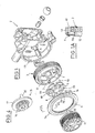
- the geared motor shown in Figures 1 to 4 is intended in particular for driving vehicle equipment such as electric window lifts.
- the geared motor also comprises a monobloc damper 5, housed inside the wheel 3 and concentrically mounted to the hub 6 thereof, which further contains radial fins 7 engaging in corresponding radial notches 8 of the shock absorber 5 made of elastic material, preferably elastomer.
- Chamfers 90 are formed on the edges of the notches 8.
- the damper 5 is provided on at least one of its faces with centering means in a cavity delimited between the wheel 3 and the output member 11. These means are, in the example described, constituted by nipples 98 coming from molding with the rest of the damper and protruding from its faces.
- the pins 98 provide the aforementioned centering and reserve the volume necessary for the swelling of the damper 5 during its compression.
- the gearbox 2 comprises an annular seal 9 and a drum 11 coaxial with the damper 5 and the wheel 3.
- This drum is intended to receive a cable, in particular for a cable-type window lifter, and constitutes the output of the geared motor.
- the seal 9 is made by overmolding, for example on a metal washer 40 (FIG. 1A) forcibly fitted into the gearbox 3.
- the seal 9 comprises at least one lip 9a slidingly abutting on an inner annular wall 12 of the wheel toothed 3.
- the annular wall 12 is necessitated by the fact that the connection wheel 3-hub 6 is outside the latter, and not interposed between the axis 4 and the wheel 3.
- the seal could be fixed on the flange and its lip slide on the housing wall 3.
- the inner annular wall 12 projects slightly longitudinally with respect to the toothing of the wheel 3, in the direction of the drum 11.
- the annular sealing gasket 9 disposed between the annular wall 12 and the wall 13 of the casing 2 thus ensures sealing of the latter, without the need to add a lid.
- the seal 9 may be secured to either the wall 13 of the housing 2, for example by means of tabs 14 resiliently snap into the housing, and sliding support on the periphery of the annular wall 12, be secured with the latter by any appropriate means, for example by tight fitting in the space between the annular wall 12 and the base of the toothed wheel 23, while being slidingly supported on the wall 13 of the casing 2.
- the drum 11 is provided with securing means in rotation with the damper 5.
- these means consist of fingers 10 of the drum 11 coming into engagement with corresponding radial notches 8.
- the notches 8 can be for example six in number, three receiving fingers 10 and three receiving the fins 7.
- the geared motor comprises an output member 15 constituted by a one-piece pinion 16 with a hub 17 (FIG. 4) inside the annular wall 12 of the toothed wheel.
- outlet 15 is preferably made of sintered steel.
- the hub 17 is equipped with fingers 30 which engage in corresponding notches 8 and which make it possible to secure the member 15 in rotation with the damper 5.
- the geared motor is provided with means for automatically adjusting the axial clearance between the end 1 of the armature shaft and the wall 18 of the casing 2 (FIG.
- these adjustment means comprise a damping abutment 19 of an elastic material such as rubber, filling the volume defined at this point by the wall 18, and a metal washer 21 embedded in the abutment 19. More exactly the Washer 21 is housed in the face of the stop 19 facing the shaft 1, so that the surface of the washer 21 is flush with the transverse face of the abutment 19.
- the end of the shaft 1 is provided with a plastic cap 22, bearing against the washer 21.
- the assembly consisting of the armature shaft 1, its end capsule 22, the washer 21 and the shock absorber 19 is mounted with a slight prestress in the wall 18, to automatically compensate for the axial play of the shaft 1.
- the end 23 of the armature shaft opposite the stop 19 is mounted in a bearing ring 24 consisting of two radially staggered portions 25, 26.
- the first portion 25 has an outer diameter equal to that of the inner wall of the stator 20 on which it bears, while its inner diameter d1 is greater than the diameter d of the shaft 23.
- the second portion 26 has an inner diameter equal to that of the shaft 23 on which it rests, and an outer diameter d2 smaller than that of the inner wall of the stator 20.
- annular gap 27 between the end 23 of the armature shaft and the portion 25, and another annular gap 28 between the portion 26 and the stator 20.
- This stepped ring 24 substantially improves the control of the play of the shaft 23, because on its portion 26 in contact with the shaft 23, the diameter may vary since this portion 26 is distant from the gap 28 of the inner wall of the stator 20. The irregularities thereof are therefore transmitted only to the portion 25, to which are transmitted the stresses on the part 26. Thus the Oscillations of the shaft 23 are significantly reduced.
- the geared motor 100 illustrated in Figure 5 is intended in particular for driving vehicle equipment, such as electric window lifts.
- armature shaft 600 carries a worm 900 meshing with a gear 110 that can drive an output member 120, which itself drives the equipment associated with the geared motor, for example a window regulator, a sunroof. .
- these adjustment means comprise a damper 150 of an elastic material such as an elastomer, arranged with a radial annular clearance (FIG. 6) in a terminal housing 170 of the end of the wall 130 of the casing 140, and a rigid abutment 180 interposed between the end of the wall 130 of the casing 140, and a rigid abutment 180 interposed between the end 600a of the shaft 600 and the damper 150.
- the rigid abutment 180 is preferably metal and forms a pellet, for example cylindrical, bearing against the end face of the damper 150, constituted for example by a cylinder of deformable material, the stop 180 is on the other hand in contact with a terminal capsule 190 fixed to the end 600a of the armature shaft 600.
- the rigid abutment 180 is axially displaceable in the casing 140 on a predetermined stroke d corresponding to the axial play of the shaft line between its position to the off-load report (Fig.6) and its position under load in operation of the gearmotor (Fig.9).
- the stroke d is limited by a stop means, constituted in the example represented by an annular transverse shoulder 210 arranged in the inner wall of the casing 140, facing the damper 150.
- the rigid stop 180 is provided with anti-rotation means around the shaft of the armature shaft 600.
- these means consist of two tabs 220 projecting radially from the periphery of the stop 180 and diametrically opposed, and which are engaged in corresponding notches 230 formed in the inner wall 130 of the housing 140.
- These notches are grooves 230 which are extend longitudinally to the transverse plane of the shoulder 210, to allow the sliding of the tabs 220 in these grooves 230 when the stop 180 travels the stroke d .
- the stop 180 Before assembly of the shaft line, the stop 180 is spaced from the clearance d of the shoulder 210 (FIG. 6). After assembly of the geared motor and without load, at rest, the shaft line 600 is in precompression with a force F1 function of the dimension d1 ( Figure 8), less than d . In this position, the damper 150 undergoes a pre-compression force of, for example, between 0 and 100 Newtons, and the remaining play or dimension d1 results from the stacking of the axial dimensions of the constituent parts of the geared motor (shaft 600, stops, casing 140 , breech etc.).
- the dimension or clearance d1 and the clearance d are illustrated in the diagram of FIG. 600, which shows that the axial force F exerted by the armature shaft 600 on the abutment 180 and on the damper 150 increases linearly from F1 to F2, that is to say until the stop 180 comes to rest against the transverse shoulder 210.
- the maximum force F2 experienced by the abutment 150 at this time is for example 100 Newtons.
- the invention is not limited to the embodiments shown and may include various variants.
- any anti-rotation means of the rigid abutment 180 may be used, a single lug or pin 220 possibly being able to be implemented.
- the device for automatically compensating the axial clearance of the shaft line is easy and therefore inexpensive to achieve, while having a long life by limiting the compression forces on the damper 150 which avoids its deterioration as previously stated.
- the seal 9 may comprise more than one lip, for example two.
Landscapes
- Engineering & Computer Science (AREA)
- Power Engineering (AREA)
- General Engineering & Computer Science (AREA)
- Mechanical Engineering (AREA)
- Connection Of Motors, Electrical Generators, Mechanical Devices, And The Like (AREA)
- Gear Transmission (AREA)
- Gears, Cams (AREA)
Claims (2)
- Getriebemotor insbesondere zum Antrieb von Fahrzeug-Zubehörteilen, umfassend einen mit einer Ankerwelle (1, 23) versehenen Läufer, ein Untersetzungsgetriebegehäuse (2), das eine Schnecke, die mit einem einen Dämpfer (5) enthaltenden Zahnrad (3) in Eingriff ist, sowie Mittel zum Abdichten des Gehäuses enthält, und ein Austrittsorgan (15), das durch den Dämpfer in Drehung versetzt wird, wobei in diesem Getriebemotor die Mittel zum Abdichten eine ringförmige Wand (12) des Zahnrads (3) und eine zwischen dieser Wand (12) und der Wand (13) des Gehäuses angeordnete Dichtung (9) umfassen, die entweder mit dem Gehäuse fest verbunden ist und an der ringförmigen Wand in gleitender Anlage ist oder mit der ringförmigen Wand fest verbunden ist und an dem Gehäuse in gleitender Anlage ist, wobei die Abdichtung zwischen mindestens einer Lippe (9a) der Dichtung (9) und dieser ringförmigen Wand hergestellt ist, wobei das Austrittsorgan (15) mit Mitteln zur festen Verbindung mit dem Dämpfer bezüglich Drehung versehen ist, dadurch gekennzeichnet, dass das Austrittsorgan (15) ein Zahnrad (16) ist, das mit einer Nabe (17) im Inneren des Zahnrads (3) einstückig ausgeführt ist, und die Nabe mit Fingern (30) versehen ist, die mit dem Dämpfer (5) zusammenwirken, um das Austrittsorgan mit dem Dämpfer bezüglich Drehung fest zu verbinden.
- Getriebemotor nach Anspruch 1, dadurch gekennzeichnet, dass das Zahnrad (16) aus Sinterstahl besteht.
Applications Claiming Priority (6)
| Application Number | Priority Date | Filing Date | Title |
|---|---|---|---|
| FR9605924A FR2748307B1 (fr) | 1996-05-03 | 1996-05-03 | Motoreducteur notamment pour l'entrainement d'equipements de vehicules |
| FR9605924 | 1996-05-13 | ||
| FR9702873A FR2760912B1 (fr) | 1997-03-11 | 1997-03-11 | Motoreducteur d'entrainement d'equipements de vehicules tels que leve-vitre, avec compensation automatique du jeu axial de sa ligne d'arbre |
| FR9702873 | 1997-03-11 | ||
| EP97924086A EP0898666B1 (de) | 1996-05-03 | 1997-05-13 | Getriebemotor, insbesondere zum antrieb von zubehörteilen in kraftfahrzeugen |
| PCT/FR1997/000848 WO1997043564A2 (fr) | 1996-05-03 | 1997-05-13 | Motoreducteur notamment pour l'entrainement d'equipements de vehicules |
Related Parent Applications (1)
| Application Number | Title | Priority Date | Filing Date |
|---|---|---|---|
| EP97924086A Division EP0898666B1 (de) | 1996-05-03 | 1997-05-13 | Getriebemotor, insbesondere zum antrieb von zubehörteilen in kraftfahrzeugen |
Publications (4)
| Publication Number | Publication Date |
|---|---|
| EP0961053A2 EP0961053A2 (de) | 1999-12-01 |
| EP0961053A3 EP0961053A3 (de) | 2000-03-01 |
| EP0961053B1 true EP0961053B1 (de) | 2007-06-27 |
| EP0961053B8 EP0961053B8 (de) | 2007-09-12 |
Family
ID=26232709
Family Applications (4)
| Application Number | Title | Priority Date | Filing Date |
|---|---|---|---|
| EP99118175A Expired - Lifetime EP0961053B8 (de) | 1996-05-03 | 1997-05-13 | Getriebemotor, insbesondere zum Antrieb von Zubehörteilen in Kraftfahrzeugen |
| EP99118174A Expired - Lifetime EP0961052B1 (de) | 1996-05-03 | 1997-05-13 | Getriebemotor, insbesondere zum Antrieb von Zubehörteilen in Kraftfahrzeugen |
| EP99118176A Expired - Lifetime EP0964185B1 (de) | 1996-05-03 | 1997-05-13 | Getriebemotor, insbesondere zum Antrieb von Zubehörteilen in Kraftfahrzeugen |
| EP97924086A Expired - Lifetime EP0898666B1 (de) | 1996-05-03 | 1997-05-13 | Getriebemotor, insbesondere zum antrieb von zubehörteilen in kraftfahrzeugen |
Family Applications After (3)
| Application Number | Title | Priority Date | Filing Date |
|---|---|---|---|
| EP99118174A Expired - Lifetime EP0961052B1 (de) | 1996-05-03 | 1997-05-13 | Getriebemotor, insbesondere zum Antrieb von Zubehörteilen in Kraftfahrzeugen |
| EP99118176A Expired - Lifetime EP0964185B1 (de) | 1996-05-03 | 1997-05-13 | Getriebemotor, insbesondere zum Antrieb von Zubehörteilen in Kraftfahrzeugen |
| EP97924086A Expired - Lifetime EP0898666B1 (de) | 1996-05-03 | 1997-05-13 | Getriebemotor, insbesondere zum antrieb von zubehörteilen in kraftfahrzeugen |
Country Status (7)
| Country | Link |
|---|---|
| US (1) | US6393929B1 (de) |
| EP (4) | EP0961053B8 (de) |
| JP (1) | JP2000510560A (de) |
| AU (1) | AU2966897A (de) |
| DE (4) | DE69721523T2 (de) |
| ES (2) | ES2218919T3 (de) |
| WO (1) | WO1997043564A2 (de) |
Families Citing this family (48)
| Publication number | Priority date | Publication date | Assignee | Title |
|---|---|---|---|---|
| FR2771469B1 (fr) * | 1997-11-27 | 2000-02-04 | Meritor Light Vehicle Sys Ltd | Motoreducteur pour l'entrainement d'equipements de vehicules tel que leve-vitre avec suppression du jeu axial de sa ligne d'arbre |
| WO2001038944A1 (de) * | 1999-11-26 | 2001-05-31 | Siemens Aktiengesellschaft | Vorrichtung zur erfassung des axialspiels |
| IT248788Y1 (it) * | 1999-11-30 | 2003-02-20 | Gate Spa | Dispositivo per la ripresa del gioco assiale in un motoriduttore. |
| DE10020901A1 (de) * | 2000-04-28 | 2001-11-22 | Diro Gmbh & Co Kg | Seilzugverstellvorrichtung |
| DE10115460A1 (de) * | 2000-03-30 | 2001-10-31 | Asmo Co Ltd | Getriebemotor mit einem verstärkten Getriebegehäuse |
| US6890279B2 (en) | 2000-06-09 | 2005-05-10 | Vkr Holding A/S | Window operator |
| JP3822462B2 (ja) * | 2000-07-27 | 2006-09-20 | アスモ株式会社 | ギヤードモータ |
| US6591707B2 (en) * | 2000-07-31 | 2003-07-15 | Asmo Co., Ltd. | Geared motor having worm wheel drivingly connected to output shaft |
| DE10042405A1 (de) * | 2000-08-30 | 2002-03-21 | Bosch Gmbh Robert | Lageraufnahme |
| DE10056133A1 (de) * | 2000-11-13 | 2002-05-23 | Zf Lenksysteme Gmbh | Elektrische Lenkvorrichtung für Kraftfahrzeuge |
| FR2836507A1 (fr) * | 2002-02-22 | 2003-08-29 | Arvinmeritor Light Vehicle Sys | Dispositif comprenant un tambour de cable maintenu par un joint dans un carter et procede d'assemblage correspondant |
| FR2836506A1 (fr) * | 2002-02-22 | 2003-08-29 | Meritor Light Vehicle Sys Ltd | Dispositif comprenant un tambour de cable maintenu par un joint dans un carter et procede d'assemblage correspondant |
| US7098562B2 (en) * | 2003-02-10 | 2006-08-29 | Siemens Vdo Automotive Corporation | Ambidextrous electronic window lift motor |
| FR2857717A1 (fr) * | 2003-07-16 | 2005-01-21 | Arvinmeritor Light Vehicle Sys | Roue et motoreducteur equipe d'une telle roue |
| DE10342074B4 (de) * | 2003-09-10 | 2012-11-22 | Brose Fahrzeugteile Gmbh & Co. Kommanditgesellschaft, Coburg | Getriebeeinheit und Motor-Getriebeeinheit für Seil-Fensterheber |
| US7258036B2 (en) * | 2003-10-20 | 2007-08-21 | Siemens Vdo Automotive Corporation | Bi-directional electric motor with endplay structure |
| DE102004002847B4 (de) * | 2004-01-19 | 2013-01-10 | Ims Gear Gmbh | KFZ-Zahnradanordnung für ein KFZ-Hilfsgetriebe und Verfahren zum Herstellen einer solchen KFZ-Zahnradanordnung |
| JP4385286B2 (ja) * | 2004-01-29 | 2009-12-16 | 株式会社ジェイテクト | 電動パワーステアリング装置 |
| GB0406887D0 (en) * | 2004-03-26 | 2004-04-28 | Boc Group Plc | Gear assembly |
| EP1619341A1 (de) * | 2004-07-23 | 2006-01-25 | Siemens Aktiengesellschaft | Kraftfahrzeug-Stellantrieb mit einem gemeinsamen Lager für die Motorwelle und die Getriebewelle |
| JP4215695B2 (ja) * | 2004-08-26 | 2009-01-28 | 株式会社ミツバ | アクチュエータ装置 |
| GB2424045A (en) * | 2005-03-07 | 2006-09-13 | John Phillip Chevalier | Centrifugal clutch which is rotationally balanced when engaged |
| DE102005045919A1 (de) * | 2005-09-26 | 2007-03-29 | Robert Bosch Gmbh | Getriebe-Antriebseinheit mit Axialspielausgleich |
| CA2612828C (en) * | 2006-12-21 | 2016-01-12 | Hunter Douglas Industries B.V. | Adjustable drive coupling for adjacent architectural coverings |
| US20080234080A1 (en) * | 2007-03-21 | 2008-09-25 | Xinjian Fan | Motorcycle wheel isolator |
| US7651173B2 (en) | 2007-07-03 | 2010-01-26 | The Gates Corporation | Wheel isolator coupling |
| DE102007035970A1 (de) * | 2007-07-30 | 2009-02-12 | Ims Gear Gmbh | Elektrische Lenkvorrichtung für Kraftfahrzeuge |
| JP5507042B2 (ja) | 2007-08-10 | 2014-05-28 | 株式会社ミツバ | 車両用窓開閉装置 |
| JP5173668B2 (ja) * | 2008-08-18 | 2013-04-03 | 株式会社ミツバ | 減速機構付モータ |
| DE102009054826A1 (de) * | 2009-12-17 | 2011-06-22 | Robert Bosch GmbH, 70469 | Elektromotor, insbesondere für einen Scheibenwischerantrieb |
| DE102010064295A1 (de) * | 2010-12-29 | 2012-07-05 | Robert Bosch Gmbh | Lagereinrichtung für eine Antriebseinheit und Verstellantrieb mit einer Lagereinrichtung |
| CN202843378U (zh) * | 2011-09-26 | 2013-04-03 | 德昌电机(深圳)有限公司 | 食物处理机、电机组件及面包机 |
| KR101328071B1 (ko) * | 2011-11-22 | 2013-11-13 | 동양기전 주식회사 | 직류 모터 장치용 웜휠 |
| JP6014272B2 (ja) * | 2012-11-30 | 2016-10-25 | コングスベルグ オートモーティヴ アクチボラゲット | シフトバイワイヤ型トランスミッション用の回転シフトアクチュエータ |
| JP6239351B2 (ja) * | 2013-05-31 | 2017-11-29 | 株式会社ミツバ | スタータ |
| US10094456B2 (en) * | 2014-05-13 | 2018-10-09 | Zhejiang Jiecang Linear Motion Technology Co., Ltd. | Actuator and applications of same |
| DE102014225992A1 (de) * | 2014-12-16 | 2016-06-16 | Robert Bosch Gmbh | Getriebe-Antriebseinrichtung und Verfahren zum Herstellen einer Getriebe-Antriebseinrichtung |
| KR101627311B1 (ko) * | 2015-01-12 | 2016-06-13 | 주식회사 만도 | 스티어링용 감속기의 웜 휠 |
| JP2016145630A (ja) * | 2015-02-09 | 2016-08-12 | 本田技研工業株式会社 | 歯車 |
| DE102015216707B4 (de) * | 2015-06-19 | 2019-09-05 | Adient Luxembourg Holding S.À R.L. | Getriebemotor, Vorrichtung zum Spielfreistellen einer Welle, und Fahrzeugsitz |
| WO2018003387A1 (ja) * | 2016-06-29 | 2018-01-04 | 株式会社ミツバ | 減速機構付モータ |
| CN109282015A (zh) * | 2017-07-20 | 2019-01-29 | 威强电工业电脑股份有限公司 | 可避免马达损坏的保护结构 |
| DE102020105409A1 (de) | 2020-02-28 | 2021-09-02 | Nidec Motors & Actuators (Germany) Gmbh | Getriebegehäuseeinheit mit Polymerelement für axialen Spielausgleich |
| DE102020105408A1 (de) | 2020-02-28 | 2021-09-02 | Nidec Motors & Actuators (Germany) Gmbh | Getriebegehäuseeinheit mit Anschlag für axialen Spielausgleich |
| DE102021205768A1 (de) * | 2021-06-08 | 2022-12-08 | Brose Fahrzeugteile Se & Co. Kommanditgesellschaft, Bamberg | Fensterheber für ein Kraftfahrzeug |
| JP7522143B2 (ja) | 2022-01-27 | 2024-07-24 | マブチモーター株式会社 | 軸受ユニットをギヤボックスに組み付ける方法 |
| CN114352155A (zh) * | 2022-01-31 | 2022-04-15 | 长春科优艾弗质量管理有限公司 | 一种汽车车窗电动玻璃升降器手动控制装置 |
| DE102023121956A1 (de) * | 2023-08-16 | 2025-02-20 | Stabilus Gmbh | Stellvorrichtung |
Family Cites Families (31)
| Publication number | Priority date | Publication date | Assignee | Title |
|---|---|---|---|---|
| US2162104A (en) * | 1936-08-05 | 1939-06-13 | Nat Oil Seal Co | Fluid seal |
| US3396556A (en) * | 1966-09-06 | 1968-08-13 | Lovejoy Flexible Coupling Comp | Flexible coupling |
| US3455174A (en) * | 1967-04-11 | 1969-07-15 | Ferro Mfg Corp | Window regulator motor and transmission housing |
| US3930566A (en) * | 1973-07-04 | 1976-01-06 | Toyota Jidosha Kogyo Kabushiki Kaisha | Device for driving a power window |
| DE2646110A1 (de) * | 1976-10-13 | 1978-04-20 | Barth Harald | Elastische klauenkupplung |
| US4090746A (en) * | 1977-04-01 | 1978-05-23 | Leeds & Northrup Company | Press fit bearing retaining bearing size when inserted into support |
| US4108447A (en) * | 1977-08-12 | 1978-08-22 | Scholin Harold W | Shaft seal |
| DE2952408A1 (de) * | 1979-04-18 | 1981-07-02 | Metallwerk Max Brose Gmbh & Co, 8630 Coburg | Elektrischer antrieb, insbesondere fuer einen fensterheber in einem kraftfahrzeug |
| US4425815A (en) * | 1980-08-29 | 1984-01-17 | Mastergear Company Limited | Wormwheels |
| US4650227B1 (en) * | 1982-08-23 | 2000-11-28 | Cajon Co | Fluid coupling |
| JPH0721289B2 (ja) * | 1983-11-15 | 1995-03-08 | 松下電器産業株式会社 | ウオームギヤ付モータの衝撃トルク吸収装置 |
| JPS62127545A (ja) * | 1985-11-26 | 1987-06-09 | Aisin Seiki Co Ltd | パワ−シ−ト用駆動装置 |
| EP0261525B1 (de) * | 1986-09-24 | 1990-04-18 | Siemens Aktiengesellschaft | Getriebeanordnung, insbesondere für Kraftfahrzeug-Fensterheberantriebe |
| US4790672A (en) * | 1986-12-19 | 1988-12-13 | International Business Machines Corporation | Pressed sleeve bearing |
| JPH0316862Y2 (de) * | 1987-01-16 | 1991-04-10 | ||
| DE3815356A1 (de) * | 1988-05-05 | 1989-11-16 | Brose Fahrzeugteile | Schneckenradgetriebe fuer einen verstellantrieb in einem kraftfahrzeug, insbesondere einer sitzverstellung |
| DE3876625D1 (de) * | 1988-09-30 | 1993-01-21 | Siemens Ag | Verstellantrieb, insbesondere kraftfahrzeug-fensterheberantrieb. |
| ES2030485T3 (es) * | 1988-09-30 | 1992-11-01 | Siemens Aktiengesellschaft | Unidad de acondicionamiento de elevalunas. |
| EP0388500A1 (de) * | 1989-03-23 | 1990-09-26 | Siemens Aktiengesellschaft | Verstellantrieb in Flachbauweise, insbesondere Kraftfahrzeug-Fensterheberantrieb |
| US5062241A (en) * | 1990-03-22 | 1991-11-05 | Masco Industries, Inc. | Varying radius helical cable spool for powered vehicle door systems |
| JP2538598Y2 (ja) * | 1990-05-14 | 1997-06-18 | 自動車電機工業株式会社 | モータ軸のスラスト受け装置 |
| JPH04165938A (ja) * | 1990-10-26 | 1992-06-11 | Matsushita Electric Ind Co Ltd | モータの緩衝装置 |
| JPH04134161U (ja) * | 1991-06-04 | 1992-12-14 | 株式会社三ツ葉電機製作所 | ウオーム減速機付モータ |
| JP2527366Y2 (ja) * | 1991-06-21 | 1997-02-26 | 株式会社ミツバ | 電装品用の減速装置 |
| US5245741A (en) * | 1991-08-14 | 1993-09-21 | Federal-Mogul Corporation | Machined shaft seal with reinforcing ring |
| DE59100439D1 (de) * | 1991-11-27 | 1993-11-04 | Siemens Ag | Verstellantrieb, insbesondere kraftfahrzeug-stellantrieb. |
| DE4210302C2 (de) * | 1992-03-28 | 1994-11-24 | Licentia Gmbh | Getriebemotor, insbesondere elektromotorischer Fensterantrieb oder Schiebedachantrieb |
| DE9209929U1 (de) * | 1992-07-23 | 1992-09-24 | Siemens AG, 8000 München | Fensterheber-Antriebseinheit |
| DE4224626A1 (de) * | 1992-07-25 | 1994-01-27 | Brose Fahrzeugteile | Antriebsvorrichtung, insbesondere für einen Fensterheber in einem Kraftfahrzeug |
| FR2748307B1 (fr) | 1996-05-03 | 1998-07-31 | Rockwell Lvs | Motoreducteur notamment pour l'entrainement d'equipements de vehicules |
| US5956998A (en) * | 1996-06-06 | 1999-09-28 | Fenelon; Paul J. | Stress reduction gear and apparatus using same |
-
1997
- 1997-05-13 WO PCT/FR1997/000848 patent/WO1997043564A2/fr not_active Ceased
- 1997-05-13 US US09/180,690 patent/US6393929B1/en not_active Expired - Fee Related
- 1997-05-13 EP EP99118175A patent/EP0961053B8/de not_active Expired - Lifetime
- 1997-05-13 DE DE69721523T patent/DE69721523T2/de not_active Expired - Lifetime
- 1997-05-13 DE DE69728692T patent/DE69728692T2/de not_active Expired - Fee Related
- 1997-05-13 DE DE69737869T patent/DE69737869T2/de not_active Expired - Lifetime
- 1997-05-13 EP EP99118174A patent/EP0961052B1/de not_active Expired - Lifetime
- 1997-05-13 DE DE69734070T patent/DE69734070T2/de not_active Expired - Lifetime
- 1997-05-13 JP JP09540597A patent/JP2000510560A/ja not_active Ceased
- 1997-05-13 ES ES99118176T patent/ES2218919T3/es not_active Expired - Lifetime
- 1997-05-13 ES ES97924086T patent/ES2197344T3/es not_active Expired - Lifetime
- 1997-05-13 EP EP99118176A patent/EP0964185B1/de not_active Expired - Lifetime
- 1997-05-13 AU AU29668/97A patent/AU2966897A/en not_active Abandoned
- 1997-05-13 EP EP97924086A patent/EP0898666B1/de not_active Expired - Lifetime
Also Published As
| Publication number | Publication date |
|---|---|
| US6393929B1 (en) | 2002-05-28 |
| EP0898666B1 (de) | 2003-05-02 |
| EP0898666A2 (de) | 1999-03-03 |
| EP0964185A2 (de) | 1999-12-15 |
| DE69728692T2 (de) | 2005-04-07 |
| EP0961053A2 (de) | 1999-12-01 |
| JP2000510560A (ja) | 2000-08-15 |
| DE69728692D1 (de) | 2004-05-19 |
| DE69721523T2 (de) | 2004-04-08 |
| DE69737869T2 (de) | 2008-02-28 |
| EP0961052A2 (de) | 1999-12-01 |
| DE69734070T2 (de) | 2006-06-14 |
| EP0964185B1 (de) | 2004-04-14 |
| AU2966897A (en) | 1997-12-05 |
| DE69737869D1 (de) | 2007-08-09 |
| EP0964185A3 (de) | 2000-03-01 |
| WO1997043564A3 (fr) | 1998-02-05 |
| EP0961053B8 (de) | 2007-09-12 |
| EP0961052A3 (de) | 2000-03-01 |
| DE69734070D1 (de) | 2005-09-29 |
| EP0961052B1 (de) | 2005-08-24 |
| ES2197344T3 (es) | 2004-01-01 |
| DE69721523D1 (de) | 2003-06-05 |
| ES2218919T3 (es) | 2004-11-16 |
| EP0961053A3 (de) | 2000-03-01 |
| WO1997043564A2 (fr) | 1997-11-20 |
Similar Documents
| Publication | Publication Date | Title |
|---|---|---|
| EP0898666B1 (de) | Getriebemotor, insbesondere zum antrieb von zubehörteilen in kraftfahrzeugen | |
| EP2926029B1 (de) | Untersetzungsgetriebe mit einem verschlussstopfen zur axialen stützung einer feder zur absorption des getriebespiels | |
| EP1399670B1 (de) | Anlasser für kraftfahrzeug mit verbessertem ritzel | |
| WO1999028656A1 (fr) | Motoreducteur pour l'entrainement d'equipements de vehicules avec suppression de jeu axial de sa ligne d'arbre | |
| EP1399671B1 (de) | Anlasser für kraftfahrzeug mit verbessertem ritzel | |
| FR3006711A1 (fr) | Systeme d'entrainement de pompe a eau et procede de montage | |
| EP0183578A1 (de) | Gehäuse und ein solches Gehäuse aufweisende Kupplung | |
| FR2573161A1 (fr) | Poulie de variateur de vitesse a joint d'etancheite autour du moyeu. | |
| EP2917557A1 (de) | Reibungsstarterantriebseinheit für den eingriff mit einem anlasserzahnkranz einer wärmekraftmaschine und entsprechender wärmekraftmaschinenanlasser | |
| EP0771958B1 (de) | Axial-komprimierbares Lager für einen Scheibenwischermechanismus | |
| FR2992367A1 (fr) | Dispositif de demarrage et procede de montage d'un dispositif de demarrage | |
| WO2003030296A2 (fr) | Rotor pour pompe a palettes | |
| FR2516878A1 (fr) | Pivot d'essuie-glace | |
| FR2797109A1 (fr) | Machine electrique tournante et demarreur ayant un faible jeu de fonctionnement axial de l'arbre d'induit | |
| EP1592881B1 (de) | Verfahren zur montage eines halterringes auf der welle eines elektrischen anlassers mit einem axial-verschiebbaren ritzel und entsprechender anlasser | |
| EP1155932A1 (de) | Lager zur Führung und axialen Positionierung einer rotierenden Welle | |
| FR3004222A1 (fr) | Ensemble porte-pignon perfectionne, lanceur, et demarreur pour vehicule automobile correspondants | |
| FR2748307A1 (fr) | Motoreducteur notamment pour l'entrainement d'equipements de vehicules | |
| FR2681911A1 (fr) | Dispositif de butee pour lanceur de demarreur pour moteur a combustion interne et procede pour la mise en óoeuvre d'un tel dispositif. | |
| WO2020039132A1 (fr) | Joint dynamique d'interface entre deux pièces mobiles en rotation l'une par rapport à l'autre, intégrant un opercule sécable | |
| FR2760912A1 (fr) | Motoreducteur d'entrainement d'equipements de vehicules tels que leve-vitre, avec compensation automatique du jeu axial de sa ligne d'arbre | |
| WO2021052941A1 (fr) | Poulie de decouplage a entrainement ameliore | |
| FR2939855A1 (fr) | Roue libre pour dispositif de poulie debrayable | |
| FR2744767A1 (fr) | Demarreur de vehicule automobile muni d'un pignon de lanceur et procede de montage d'un tel lanceur | |
| EP1778970A1 (de) | Anlasser, insbesondere für mit einem friktionsgetriebenen freilaufantrieb ausgestattetes kraftfahrzeug |
Legal Events
| Date | Code | Title | Description |
|---|---|---|---|
| PUAI | Public reference made under article 153(3) epc to a published international application that has entered the european phase |
Free format text: ORIGINAL CODE: 0009012 |
|
| 17P | Request for examination filed |
Effective date: 19990913 |
|
| AC | Divisional application: reference to earlier application |
Ref document number: 898666 Country of ref document: EP |
|
| AK | Designated contracting states |
Kind code of ref document: A2 Designated state(s): DE ES GB IT |
|
| PUAL | Search report despatched |
Free format text: ORIGINAL CODE: 0009013 |
|
| AK | Designated contracting states |
Kind code of ref document: A3 Designated state(s): DE ES GB IT |
|
| RIC1 | Information provided on ipc code assigned before grant |
Free format text: 7F 16H 1/16 A, 7E 05F 15/16 B, 7H 02K 7/08 B, 7H 02K 7/116 B |
|
| RIN1 | Information on inventor provided before grant (corrected) |
Inventor name: LAURANDEL, HERVE Inventor name: QUERE, JEROME |
|
| AKX | Designation fees paid |
Free format text: DE ES GB IT |
|
| 17Q | First examination report despatched |
Effective date: 20030818 |
|
| 17Q | First examination report despatched |
Effective date: 20050905 |
|
| GRAP | Despatch of communication of intention to grant a patent |
Free format text: ORIGINAL CODE: EPIDOSNIGR1 |
|
| GRAS | Grant fee paid |
Free format text: ORIGINAL CODE: EPIDOSNIGR3 |
|
| GRAA | (expected) grant |
Free format text: ORIGINAL CODE: 0009210 |
|
| AC | Divisional application: reference to earlier application |
Ref document number: 0898666 Country of ref document: EP Kind code of ref document: P |
|
| AK | Designated contracting states |
Kind code of ref document: B1 Designated state(s): DE ES GB IT |
|
| REG | Reference to a national code |
Ref country code: GB Ref legal event code: FG4D Free format text: NOT ENGLISH |
|
| RAP2 | Party data changed (patent owner data changed or rights of a patent transferred) |
Owner name: ARVINMERITOR LIGHT VEHICLE SYSTEMS-FRANCE |
|
| REF | Corresponds to: |
Ref document number: 69737869 Country of ref document: DE Date of ref document: 20070809 Kind code of ref document: P |
|
| GBT | Gb: translation of ep patent filed (gb section 77(6)(a)/1977) |
Effective date: 20070911 |
|
| REG | Reference to a national code |
Ref country code: ES Ref legal event code: FG2A Ref document number: 2289799 Country of ref document: ES Kind code of ref document: T3 |
|
| PLBE | No opposition filed within time limit |
Free format text: ORIGINAL CODE: 0009261 |
|
| STAA | Information on the status of an ep patent application or granted ep patent |
Free format text: STATUS: NO OPPOSITION FILED WITHIN TIME LIMIT |
|
| 26N | No opposition filed |
Effective date: 20080328 |
|
| GBPC | Gb: european patent ceased through non-payment of renewal fee |
Effective date: 20080513 |
|
| PG25 | Lapsed in a contracting state [announced via postgrant information from national office to epo] |
Ref country code: GB Free format text: LAPSE BECAUSE OF NON-PAYMENT OF DUE FEES Effective date: 20080513 |
|
| REG | Reference to a national code |
Ref country code: ES Ref legal event code: FD2A Effective date: 20080514 |
|
| PG25 | Lapsed in a contracting state [announced via postgrant information from national office to epo] |
Ref country code: IT Free format text: LAPSE BECAUSE OF NON-PAYMENT OF DUE FEES Effective date: 20080513 |
|
| PG25 | Lapsed in a contracting state [announced via postgrant information from national office to epo] |
Ref country code: ES Free format text: LAPSE BECAUSE OF NON-PAYMENT OF DUE FEES Effective date: 20080514 |
|
| PGFP | Annual fee paid to national office [announced via postgrant information from national office to epo] |
Ref country code: DE Payment date: 20120510 Year of fee payment: 16 |
|
| PG25 | Lapsed in a contracting state [announced via postgrant information from national office to epo] |
Ref country code: DE Free format text: LAPSE BECAUSE OF NON-PAYMENT OF DUE FEES Effective date: 20131203 |
|
| REG | Reference to a national code |
Ref country code: DE Ref legal event code: R119 Ref document number: 69737869 Country of ref document: DE Effective date: 20131203 |