EP0961104A2 - Optische Signalquelle für faseroptische interferometrische Sensoren - Google Patents
Optische Signalquelle für faseroptische interferometrische Sensoren Download PDFInfo
- Publication number
- EP0961104A2 EP0961104A2 EP99304090A EP99304090A EP0961104A2 EP 0961104 A2 EP0961104 A2 EP 0961104A2 EP 99304090 A EP99304090 A EP 99304090A EP 99304090 A EP99304090 A EP 99304090A EP 0961104 A2 EP0961104 A2 EP 0961104A2
- Authority
- EP
- European Patent Office
- Prior art keywords
- fiber
- light
- optical
- pump light
- wavelength division
- Prior art date
- Legal status (The legal status is an assumption and is not a legal conclusion. Google has not performed a legal analysis and makes no representation as to the accuracy of the status listed.)
- Granted
Links
Images


Classifications
-
- H—ELECTRICITY
- H01—ELECTRIC ELEMENTS
- H01S—DEVICES USING THE PROCESS OF LIGHT AMPLIFICATION BY STIMULATED EMISSION OF RADIATION [LASER] TO AMPLIFY OR GENERATE LIGHT; DEVICES USING STIMULATED EMISSION OF ELECTROMAGNETIC RADIATION IN WAVE RANGES OTHER THAN OPTICAL
- H01S3/00—Lasers, i.e. devices using stimulated emission of electromagnetic radiation in the infrared, visible or ultraviolet wave range
- H01S3/05—Construction or shape of optical resonators; Accommodation of active medium therein; Shape of active medium
- H01S3/06—Construction or shape of active medium
- H01S3/063—Waveguide lasers, i.e. whereby the dimensions of the waveguide are of the order of the light wavelength
- H01S3/067—Fibre lasers
- H01S3/06795—Fibre lasers with superfluorescent emission, e.g. amplified spontaneous emission sources for fibre laser gyrometers
-
- G—PHYSICS
- G01—MEASURING; TESTING
- G01C—MEASURING DISTANCES, LEVELS OR BEARINGS; SURVEYING; NAVIGATION; GYROSCOPIC INSTRUMENTS; PHOTOGRAMMETRY OR VIDEOGRAMMETRY
- G01C19/00—Gyroscopes; Turn-sensitive devices using vibrating masses; Turn-sensitive devices without moving masses; Measuring angular rate using gyroscopic effects
- G01C19/58—Turn-sensitive devices without moving masses
- G01C19/64—Gyrometers using the Sagnac effect, i.e. rotation-induced shifts between counter-rotating electromagnetic beams
- G01C19/72—Gyrometers using the Sagnac effect, i.e. rotation-induced shifts between counter-rotating electromagnetic beams with counter-rotating light beams in a passive ring, e.g. fibre laser gyrometers
- G01C19/721—Details, e.g. optical or electronical details
Definitions
- This invention relates generally to an optical signal source for a fiber optic interferometric sensor. More particularly, this invention relates to an optical signal source for a fiber optic rotation sensor. Still more particularly, this invention relates to an optical signal source that includes a gain fiber that is optically pumped to produce a broadband optical signal. The invention provides apparatus for eliminating backward reflections of the pump light in a double-pass optical pumped gain fiber.
- a double-pass optical pumped gain fiber produces greater signal intensity than can be obtained with a single pass of the pump light through a gain fiber.
- the gain fiber normally is doped with erbium, that produces gain in the optical signal frequency used in fiber optic rotation sensors.
- the typical broadband fiber source used in fiber optic gyros is a reverse pumped, single-pass fiber source.
- This configuration uses a laser diode that emits light at a given wavelength. This light is directed through a wavelength division multiplexer, WDM, that has two input leads and two output leads. One of the output leads of the WDM is physically connected to a length of erbium doped fiber, EDF.
- the EDF is terminated at one end with an angle capillary tube that keeps the light from being reflected back into the fiber.
- the EDF has a core that has been doped such that spontaneous emission occurs when light of a specific wavelength and sufficiently high intensity is launched into the core. This emission occurs in both directions of the EDF.
- the light emitted in the reverse direction is directed back towards the WDM.
- This light is at a different wavelength from the pump light introduced by the laser diode.
- the WDM typically is optimized to separate the two wavelengths.
- Light from the EDF is at a wavelength such that it gets coupled into the fiber leg that is not connected to the laser diode. This light, which is broadband in nature, is then coupled into the fiber optic gyro.
- the angled capillary is replaced with a reflector that preferably is a dichroic mirror.
- the reflector may alternatively be a Bragg grating or a straight cleave on the end of the optical fiber.
- the dichroic mirror causes the light in the forward direction to be reflected back in the reverse direction.
- the problems as stated above with a double-pass configuration arise when the source is used as the optical signal source for a fiber optic rotation sensor.
- Half the light from the gyro is directed back into the broadband source because the gyro uses a fiber optic multiplexer (MUX) to separate the input light from the output light.
- MUX fiber optic multiplexer
- This MUX is typically a 50/50 optical coupler.
- the light that is directed back into the broadband source acts to reduce the efficiency of the erbium fiber by a process called gain depletion. This problem is encountered with both the single reverse pump and double-pass configurations.
- the second problem encountered is especially prevalent in the double-pass configuration.
- all three fiber optic gyros are tied together for use as a three-axis inertial measurement unit, IMU, all three axes use the same broadband light source. This allows for a significant cost savings since three individual light sources are not needed.
- the light from one gyro that is reflected back due to the feedback described above can be reflected back into any one of the three axes. This creates a cross-coupling error term for each of the three gyros.
- back reflections in the erbium gain fiber create etalons that collapse the broadband spectrum into a very narrow spectrum.
- This condition is unstable and introduces bias and scale factor instabilities into the gyro.
- the coherence length of the source becomes very long that allows for the introduction of polarization non-reciprocal (PNR) bias errors.
- PNR polarization non-reciprocal
- the optical signal source includes a pump light source arranged to provide pump light to a gain fiber.
- a first optical isolation device is arranged to receive the pump light, and a wavelength division multiplexer is arranged to receive pump light that passes through the optical isolation device.
- the gain fiber is connected to the wavelength division multiplexer and arranged to be optically pumped by the pump light to emit broadband light that propagates to the wavelength division multiplexer.
- An output optical fiber is connected to the wavelength division multiplexer and arranged to guide a portion of the broadband light emitted by the gain fiber.
- a second optical isolation device is connected to the output optical fiber.
- the gain fiber preferably comprises a length of optical fiber doped with erbium.
- the optical signal source preferably includes a reflector connected to an end of the gain fiber such that both forward emitted light and backwards emitted light propagate in the gain fiber to the wavelength division multiplexer for introduction into the output fiber.
- the reflector preferably is formed as a dichroic mirror.
- FIG. 1 illustrates a reverse pumped, double-pass optical signal source 10 according to the present invention.
- the optical signal source 10 is arranged to provide optical signals to a fiber optic rotation sensor 12.
- the optical signal source 10 includes a pump light source 14, which preferably comprises a laser diode, arranged to provide pump light to an optical fiber 16.
- An optical isolator 18 has an optical fiber pigtail 20 that is connected to the optical fiber 16 at a splice 22. The pump light propagates to the optical isolator 18 and exits the isolator 18 via an optical fiber pigtail 24.
- a WDM coupler 26 has optical fiber pigtails 28-31 extending therefrom.
- the pigtail 28 is connected to the pigtail 24 via a splice 32 so that after passing through the optical isolator 18, the pump light then propagates to the WDM coupler 26.
- the WDM coupler 26 guides the pump light into a gain fiber 34 that is connected end-to-end with the optical fiber pigtail 31 via a splice 36.
- the pump light has a wavelength of about 1480 nm in a preferred embodiment of the invention.
- the gain fiber 34 typically is an erbium-doped fiber, which is well-known in the art.
- the erbium-doped gain fiber 34 has a three level transition that produces a broadband optical signal having a wavelength centered at 1550 nm.
- U.S. Patent 5,231,465, issued February 8, 1991 and U.S. Patent 5,119,229 issued June 2, 1992 disclose the use of erbium-doped cores to provide optical signal in an optical fiber.
- the gain fiber 34 absorbs part of the pump light and emits light propagating lengthwise in both directions in the gain fiber 34.
- Light emitted in the direction of propagation direction of the pump light is referred to as forward light.
- Light emitted by the gain fiber 34 opposite in direction to the direction of propagation of the pump light is referred to as reverse light.
- the forward light reflects from a reflector 38 which terminates the gain fiber 34.
- the reflector 38 preferably is a dichroic mirror, but may be a Bragg grating or a straight cleave on the end of the optical fiber.
- the dichroic mirror 38 causes the light emitted in the forward direction to be reflected back in the reverse direction so that both the reverse light and the forward light are directed to the WDM coupler 26.
- the pump light does not reflect from the dichroic mirror 38.
- the WDM coupler 26 directs the light emitted from the gain fiber 34 to the fiber optic rotation sensor 12 via the optical fiber pigtail 29.
- the pigtail fiber 29 is connected via a splice 44 to a fiber optic pigtail 48 that serves an input to an isolator 50.
- the optical isolator 50 provides an optical output to a fiber optic pigtail 52.
- the optical signal After passing through the isolator 50, the optical signal propagates to a multiplexer 54.
- the multiplexer 54 includes three optical fiber pigtails 56-58.
- the output fiber optic pigtail 52 of the optical isolator 50 is spliced to the optical fiber 56 at a splice 60.
- the optical signal from the optical signal source 10 then passes through the multiplexer 54 to the optical fiber pigtail 57.
- a splice 62 connects the multiplexer pigtail 57 to a pigtail 64 that is connected multifunction integrated optics chip (MIOC) 66, which includes well-known components used to form, and process the counter-propagating waves used in fiber optic rotation sensor systems. Suitable MIOC structures are disclosed in U.S. Patent Nos. 4,915,503; 4,997,282; and 5,037,205.
- MIOC multifunction integrated optics chip
- the MIOC 66 is connected to optical fiber pigtails 67 and 68.
- a pair of splices 70 and 72 connect the MIOC pigtails 67 and 68, respectively, to a fiber optic sensing coil 74.
- the MIOC 66 processes light input form the optical signal source to provide counter-propagating waves to the fiber optic sensing coil 74.
- Rotation of the fiber optic rotation sensor 12 about a line perpendicular to the plane of the sensing coil 74 produces a phase difference in the counter-propagating waves by means of the Sagnac effect.
- the counter-propagating waves combine in the MIOC 66 and form an interference pattern.
- the combined counter-propagating waves then exit the MIOC 66 and enter the multiplexer 54.
- the optical fiber pigtail 58 of the multiplexer 54 then guides the combined waves to a fiber 76 that is connected to the pigtail 58 via a splice 78.
- the optical fiber 76 then guides the combined counter-propagating waves to a photodetector 80.
- the photodetector 80 produces electrical signals that indicate the intensity of the interference pattern produced by combining the waves that have propagated through the sensing coil.
- Signal processing circuitry (not shown) then may be used to measure rotation of the sensing coil.
- the isolator 50 acts to allow light to travel towards the MIOC 66 but stops light from propagating back toward the broadband light source 10.
- the isolators 18 and 50 may include several micro-optic bulk components.
- the isolator 50 has two fiber pigtails, a collimating lens on the input, a birefringent element, a Faraday rotator, a second birefringent element and a lens to couple the light back into the output fiber pigtail.
- Light entering the isolator is first collimated and then split into ordinary and extraordinary beams. Each of these beams are rotated 45° by the Faraday rotator.
- the two beams then enter the second birefringent element that has been aligned at 45° to the first element that allows the light beams to pass through.
- the light beams are then coupled into the output fiber pigtail.
- Light entering the isolator 50 from the reverse direction gets rotated by the Faraday rotator in non-reciprocal fashion and is rejected by the first birefringent element. Rejection of 40 to 60 dB is achievable with this type of an optical isolator.
- the optical isolator can be made with micro-bulk optic components or thin film components.
- the optical signal source according to the present invention includes the isolator 18 in addition to the isolator 50.
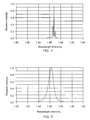
- FIGS. 2-5 illustrate the effect of forming the fiber optic signal source to include the isolators 18 and 50.
- FIG. 2 shows the spectrum for a single-pass broadband fiber source that is being pumped with high pump power (> 50 milliwatts). The data for FIG. 2 is for an optical circuit that includes the isolator 50, but not the isolator 18. It should be noted that the single-pass light source does not include the dichroic mirror 38, but instead typically includes an angled capillary that guides the forward emitted light out of the gain fiber 34. This spectrum shown in FIG. 2 is typical for broadband fiber sources operating near saturation.
- FIG. 3 is a spectrum that represents a double-pass light source (not shown) having the isolator 50 and having the reflector 38 formed as a straight cleave in the gain fiber 34 instead of the preferred dichroic mirror.
- a straight cleave typically gives a 4% reflection of the forward light to create a double-pass system.
- FIG. 3 shows that the spectrum collapses into two narrow peaks that are unusable in a fiber optic gyroscope.
- FIG. 4 is a spectrum obtained by omitting the isolator 18 from FIG. 1.
- the dichroic mirror reflector creates an efficient double-pass configuration which has a spectrum that also collapses to several narrow peaks.
- FIG. 5 shows the spectrum obtained from the optical signal source shown in FIG. 1.
- Including the isolator 18 between the pump light source 14, preferably a laser diode, and the WDM coupler 26 removes reflections from the pump light source 14 and thus spoils the cavity that creating the lasing that produced the multiple peaks in the optical signal output.
- the result of including the two optical isolators 18 and 50 in the system is the single broad peak spectrum of FIG. 5.
- the single peak spectrum has the advantage of adding scale stability to the gyro when the source is exposed to ionizing radiation.
- the fiber optic rotation sensor architecture of FIG. 1 may include a servo system 82 arranged to maintain the intensity and wavelength of the pump light at constant values.
- the servo system eliminates the effect of temperature variations on the output of the pump light source 14.
- the servo system 82 may include an optical coupler 84 arranged to tap a small amount (1% for example) of the pump light out to the optical fiber 18 into an optical fiber 86.
- the servo system 82 receives the light tapped out of the optical fiber 18 and produces feedback signals that are input to the pump light source 14 to stabilize either one or both of intensity and wavelength.
- the coupler 84 in the servo system may be located at various positions in the fiber optic rotation sensor architecture.
- the coupler may be located at point A after the isolator 18 in the optical fiber 28 or at point B after the WDM coupler 26 in the optical fiber pigtail 31.
- a long period grating that provides loss at 1.56 ⁇ m by diverting the light to the cladding could be used. This has the advantages of (a) lower transmission loss at the 1480 nm pump wavelength than an in-line optical isolator, (b) a lower cost, (c) requiring very little volume and weight, and (d) preserving the all-fiber architecture and reliability.
- the use of a long period grating is particularly attractive if Bragg fiber grating has to be used to control the pump wavelength of the laser diode as the two gratings can be written on the same fiber.
- the isolation ratio at 1.56 ⁇ m of a long period grating may not be as good as the isolator.
- the front facet of the laser diode and a double-pass of the WDM already provide a return loss of at least -30 dB, a total rejection of -50 dB is readily attainable with a 10 dB long period grating and is more than adequate to suppress oscillation.
Landscapes
- Physics & Mathematics (AREA)
- Engineering & Computer Science (AREA)
- Electromagnetism (AREA)
- Optics & Photonics (AREA)
- Power Engineering (AREA)
- General Physics & Mathematics (AREA)
- Radar, Positioning & Navigation (AREA)
- Remote Sensing (AREA)
- Plasma & Fusion (AREA)
- Lasers (AREA)
- Gyroscopes (AREA)
- Optical Transform (AREA)
Applications Claiming Priority (2)
| Application Number | Priority Date | Filing Date | Title |
|---|---|---|---|
| US09/087,350 US6330105B1 (en) | 1998-05-29 | 1998-05-29 | Double-pass fully isolated broadband optical signal source for fiber optic interferometric sensors |
| US87350 | 1998-05-29 |
Publications (3)
| Publication Number | Publication Date |
|---|---|
| EP0961104A2 true EP0961104A2 (de) | 1999-12-01 |
| EP0961104A3 EP0961104A3 (de) | 2001-03-21 |
| EP0961104B1 EP0961104B1 (de) | 2005-01-19 |
Family
ID=22204665
Family Applications (1)
| Application Number | Title | Priority Date | Filing Date |
|---|---|---|---|
| EP99304090A Expired - Lifetime EP0961104B1 (de) | 1998-05-29 | 1999-05-26 | Optische Signalquelle für faseroptische interferometrische Sensoren |
Country Status (5)
| Country | Link |
|---|---|
| US (1) | US6330105B1 (de) |
| EP (1) | EP0961104B1 (de) |
| JP (1) | JP2000036630A (de) |
| DE (1) | DE69923251T2 (de) |
| IL (1) | IL130151A (de) |
Cited By (5)
| Publication number | Priority date | Publication date | Assignee | Title |
|---|---|---|---|---|
| WO2002005395A3 (en) * | 2000-07-07 | 2002-05-30 | Litton Systems Inc | Source, system and method for generating amplified stimulated emissions |
| EP1073170A3 (de) * | 1999-07-30 | 2003-01-29 | Litton Systems, Inc. | Wellenlängenstabilisierte Laserlichtquelle |
| WO2002060019A3 (en) * | 2000-07-05 | 2004-02-19 | Northrop Grumman Corp | Source, system and method for generating amplified stimulated emission |
| WO2005053120A1 (en) * | 2003-11-20 | 2005-06-09 | Northrop Grumman Corporation | Long period bragg grating optical signal attenuation |
| EP2261708A1 (de) * | 2009-06-01 | 2010-12-15 | Honeywell International Inc. | Interferometrisches faseroptisches Gyroskop mit optischer Silicium-Bankvorderseite |
Families Citing this family (29)
| Publication number | Priority date | Publication date | Assignee | Title |
|---|---|---|---|---|
| US20030145353A1 (en) * | 1997-05-07 | 2003-07-31 | Lightner Jonathan E. | Starch biosynthetic enzymes |
| US7139080B2 (en) * | 1998-09-18 | 2006-11-21 | Zygo Corporation | Interferometry systems involving a dynamic beam-steering assembly |
| US6888638B1 (en) | 1999-05-05 | 2005-05-03 | Zygo Corporation | Interferometry system having a dynamic beam steering assembly for measuring angle and distance |
| US6512588B1 (en) | 1999-05-05 | 2003-01-28 | Zygo Corporation | Method and system for correcting an interferometric angle measurement for the effects of dispersion |
| US6541759B1 (en) * | 2000-06-20 | 2003-04-01 | Zygo Corporation | Interferometry system having a dynamic beam-steering assembly for measuring angle and distance and employing optical fibers for remote photoelectric detection |
| JP2002198594A (ja) * | 2000-12-25 | 2002-07-12 | Kyocera Corp | 広帯域ase光源 |
| JP4030960B2 (ja) * | 2001-08-23 | 2008-01-09 | ザイゴ コーポレーション | 入力ビームの方向の動的干渉分光制御 |
| US6836334B2 (en) * | 2001-10-31 | 2004-12-28 | Kvh Industries, Inc. | Angle random walk (ARW) noise reduction in fiber optic sensors using an optical amplifier |
| US6765678B2 (en) * | 2002-01-08 | 2004-07-20 | Honeywell International Inc. | Relative intensity noise controller with maximum gain at frequencies at or above the bias modulation frequency or with second order feedback for fiber light sources |
| US6856402B2 (en) * | 2002-02-12 | 2005-02-15 | Zygo Corporation | Interferometer with dynamic beam steering element |
| JP4279679B2 (ja) * | 2002-02-12 | 2009-06-17 | ザイゴ コーポレーション | 干渉法システムにおける非サイクリック・エラーの特性評価および補償 |
| US6906784B2 (en) * | 2002-03-04 | 2005-06-14 | Zygo Corporation | Spatial filtering in interferometry |
| WO2003095940A2 (en) * | 2002-05-13 | 2003-11-20 | Zygo Corporation | Compensation for geometric effects of beam misalignments in plane mirror interferometers |
| US7262860B2 (en) * | 2002-07-29 | 2007-08-28 | Zygo Corporation | Compensation for errors in off-axis interferometric measurements |
| DE10393243T5 (de) * | 2002-09-09 | 2005-09-01 | Zygo Corp., Middlefield | Messung und Fehlerausgleichung bei Interferometern |
| US7274462B2 (en) * | 2002-09-09 | 2007-09-25 | Zygo Corporation | In SITU measurement and compensation of errors due to imperfections in interferometer optics in displacement measuring interferometry systems |
| US7075619B2 (en) * | 2002-12-12 | 2006-07-11 | Zygo Corporation | In-process correction of stage mirror deformations during a photolithography exposure cycle |
| US7327465B2 (en) * | 2003-06-19 | 2008-02-05 | Zygo Corporation | Compensation for effects of beam misalignments in interferometer metrology systems |
| US7286240B2 (en) | 2003-06-19 | 2007-10-23 | Zygo Corporation | Compensation for geometric effects of beam misalignments in plane mirror interferometer metrology systems |
| US7180603B2 (en) * | 2003-06-26 | 2007-02-20 | Zygo Corporation | Reduction of thermal non-cyclic error effects in interferometers |
| WO2005045529A2 (en) * | 2003-11-04 | 2005-05-19 | Zygo Corporation | Characterization and compensation of errors in multi-axis interferometry system |
| WO2005067815A1 (en) * | 2004-01-05 | 2005-07-28 | Zygo Corporation | Stage alignment in lithography tools |
| US7283248B2 (en) * | 2004-01-06 | 2007-10-16 | Zygo Corporation | Multi-axis interferometers and methods and systems using multi-axis interferometers |
| US7375823B2 (en) * | 2004-04-22 | 2008-05-20 | Zygo Corporation | Interferometry systems and methods of using interferometry systems |
| JP2007534941A (ja) * | 2004-04-22 | 2007-11-29 | ザイゴ コーポレーション | 光学干渉計システムおよび光学干渉計システムを用いる方法 |
| US7489407B2 (en) * | 2004-10-06 | 2009-02-10 | Zygo Corporation | Error correction in interferometry systems |
| US7187816B2 (en) * | 2004-12-13 | 2007-03-06 | Purdue Research Foundation | In-fiber whitelight interferometry using long-period fiber grating |
| US7433049B2 (en) * | 2005-03-18 | 2008-10-07 | Zygo Corporation | Multi-axis interferometer with procedure and data processing for mirror mapping |
| US9541399B2 (en) * | 2012-11-14 | 2017-01-10 | Northrop Grumman Guidance And Electronics Company, Inc. | Fiber optic gyroscope with front end polarizer |
Family Cites Families (17)
| Publication number | Priority date | Publication date | Assignee | Title |
|---|---|---|---|---|
| FR2402956A1 (fr) * | 1977-09-08 | 1979-04-06 | Comp Generale Electricite | Chaine d'amplification laser |
| US4938556A (en) | 1983-11-25 | 1990-07-03 | The Board Of Trustees Of The Leland Stanford Junior University | Superfluorescent broadband fiber laser source |
| US4637255A (en) | 1985-12-30 | 1987-01-20 | Litton Systems, Inc. | Non-planar ring laser accelerometer |
| US4792956A (en) | 1986-05-13 | 1988-12-20 | Litton Systems, Inc. | Laser diode intensity and wavelength control |
| US4997282A (en) | 1986-09-19 | 1991-03-05 | Litton Systems, Inc. | Dual fiber optic gyroscope |
| US4887900A (en) | 1987-02-20 | 1989-12-19 | Litton Systems, Inc. | Polarization maintaining fiber interferometer and method for source stabilization |
| US4890922A (en) | 1987-02-20 | 1990-01-02 | Litton Systems, Inc. | Thermally compensated reference interferometer and method |
| US4842358A (en) | 1987-02-20 | 1989-06-27 | Litton Systems, Inc. | Apparatus and method for optical signal source stabilization |
| US4915503A (en) | 1987-09-01 | 1990-04-10 | Litton Systems, Inc. | Fiber optic gyroscope with improved bias stability and repeatability and method |
| US5037205A (en) | 1989-04-19 | 1991-08-06 | Litton Systems, Inc. | Integrated optic interferometric fiber gyroscope module and method |
| IT1236632B (it) | 1989-10-24 | 1993-03-25 | Pirelli Cavi Spa | Amplificatore per linee di telecomunicazioni a fibre ottiche e linee di telecomunicazioni a fibre ottiche incorporanti detto amplificatore |
| US5185749A (en) * | 1990-09-18 | 1993-02-09 | The Board Of Trustee Of The Leland Stanford Junior University | Large signal three-level superfluorescent fiber sources |
| US5177562A (en) | 1990-09-18 | 1993-01-05 | The Board Of Trustees Of The Leland Stanford Junior University | Stability compensated broadband source and fiber interferometer |
| US5231465A (en) | 1991-02-08 | 1993-07-27 | Litton Systems, Inc. | High efficiency fiber absorber and method for attenuating pump light in a broadband fiber optic light source |
| US5311603A (en) * | 1992-10-28 | 1994-05-10 | Litton Systems Inc. | Highly efficient superfluorescent fiber laser/amplifier for interferometric sensors |
| US5331404A (en) * | 1992-11-30 | 1994-07-19 | The United States Of America As Represented By The Secretary Of The Navy | Low noise fiber gyroscope system which includes excess noise subtraction |
| US6122095A (en) * | 1997-08-29 | 2000-09-19 | Lucent Technologies Inc. | Wavelength-selective and loss-less optical add/drop multiplexer |
-
1998
- 1998-05-29 US US09/087,350 patent/US6330105B1/en not_active Expired - Lifetime
-
1999
- 1999-05-26 DE DE69923251T patent/DE69923251T2/de not_active Expired - Fee Related
- 1999-05-26 EP EP99304090A patent/EP0961104B1/de not_active Expired - Lifetime
- 1999-05-26 IL IL13015199A patent/IL130151A/xx not_active IP Right Cessation
- 1999-05-28 JP JP11188066A patent/JP2000036630A/ja active Pending
Cited By (7)
| Publication number | Priority date | Publication date | Assignee | Title |
|---|---|---|---|---|
| EP1073170A3 (de) * | 1999-07-30 | 2003-01-29 | Litton Systems, Inc. | Wellenlängenstabilisierte Laserlichtquelle |
| WO2002060019A3 (en) * | 2000-07-05 | 2004-02-19 | Northrop Grumman Corp | Source, system and method for generating amplified stimulated emission |
| WO2002005395A3 (en) * | 2000-07-07 | 2002-05-30 | Litton Systems Inc | Source, system and method for generating amplified stimulated emissions |
| WO2005053120A1 (en) * | 2003-11-20 | 2005-06-09 | Northrop Grumman Corporation | Long period bragg grating optical signal attenuation |
| US7233724B2 (en) | 2003-11-20 | 2007-06-19 | Northrop Grumman Corporation | Long period bragg grating optical signal attenuation |
| EP2261708A1 (de) * | 2009-06-01 | 2010-12-15 | Honeywell International Inc. | Interferometrisches faseroptisches Gyroskop mit optischer Silicium-Bankvorderseite |
| US8103140B2 (en) | 2009-06-01 | 2012-01-24 | Honeywell International Inc. | Interferometric fiber optic gyroscope with silicon optical bench front-end |
Also Published As
| Publication number | Publication date |
|---|---|
| EP0961104A3 (de) | 2001-03-21 |
| DE69923251T2 (de) | 2006-03-30 |
| IL130151A (en) | 2003-12-10 |
| IL130151A0 (en) | 2000-06-01 |
| EP0961104B1 (de) | 2005-01-19 |
| US6330105B1 (en) | 2001-12-11 |
| DE69923251D1 (de) | 2005-02-24 |
| JP2000036630A (ja) | 2000-02-02 |
Similar Documents
| Publication | Publication Date | Title |
|---|---|---|
| EP0961104B1 (de) | Optische Signalquelle für faseroptische interferometrische Sensoren | |
| US6246816B1 (en) | Wavelength stabilized laser light source | |
| EP0812039B1 (de) | Faserlichtquelle mit Multimodefaserkoppler | |
| US6041072A (en) | Apparatus for stabilizing multiple laser sources and their application | |
| US5311603A (en) | Highly efficient superfluorescent fiber laser/amplifier for interferometric sensors | |
| US20080291459A1 (en) | Fiber optic gyroscope with integrated light source | |
| EP0489847B1 (de) | Interferometer unter benutzung superfluoreszierender optischer quellen | |
| US6025915A (en) | Scale factor stabilization of a broadband fiber source used in fiber optic gyroscopes in radiation environments | |
| EP1562315A1 (de) | Optischer Raman-Verstärker mit passenden Pumpquelle | |
| JP2640588B2 (ja) | 干渉計、その製造および感知方法 | |
| US6429965B1 (en) | Polarization and wavelength stable superfluorescent sources | |
| EP0893671B1 (de) | Vorrichtung und Verfahren zur Skalenfaktorstabilisation in interferometrischen faseroptischen Rotationssensoren | |
| CA2050538C (en) | Residual pump light attenuating fibre using yb and erbium atoms in rotation sensor systems | |
| EP1125346B1 (de) | Polarisations- und wellenlängenstabile superfluoreszenz-lichtquellen | |
| US6205265B1 (en) | Apparatus and method for isolated photobleaching fiber optic rotation sensor coils | |
| US5608524A (en) | Coherence collapsed multimode source for a fiber optic gyro | |
| JPH06181352A (ja) | 光増幅器用光モジュール | |
| US6584246B1 (en) | Source, system and method for generating amplified stimulated emission using a coupler mechanism | |
| JPH0764021A (ja) | 光結合器及び光ファイバ増幅器 | |
| EP0366756A1 (de) | Optische faser-breitbandlaser | |
| CN117109551A (zh) | 一种高精度光纤陀螺用保偏ase光源 | |
| JPH07245439A (ja) | 光ファイバレーザ | |
| JPH05113512A (ja) | 損失補償型光分岐回路 | |
| JPH07218271A (ja) | 光ファイバジャイロ | |
| JP2002198594A (ja) | 広帯域ase光源 |
Legal Events
| Date | Code | Title | Description |
|---|---|---|---|
| PUAI | Public reference made under article 153(3) epc to a published international application that has entered the european phase |
Free format text: ORIGINAL CODE: 0009012 |
|
| AK | Designated contracting states |
Kind code of ref document: A2 Designated state(s): DE FR GB IT |
|
| AX | Request for extension of the european patent |
Free format text: AL;LT;LV;MK;RO;SI |
|
| PUAL | Search report despatched |
Free format text: ORIGINAL CODE: 0009013 |
|
| AK | Designated contracting states |
Kind code of ref document: A3 Designated state(s): AT BE CH CY DE DK ES FI FR GB GR IE IT LI LU MC NL PT SE |
|
| AX | Request for extension of the european patent |
Free format text: AL;LT;LV;MK;RO;SI |
|
| 17P | Request for examination filed |
Effective date: 20010831 |
|
| AKX | Designation fees paid |
Free format text: DE FR GB IT |
|
| RAP1 | Party data changed (applicant data changed or rights of an application transferred) |
Owner name: LITTON SYSTEMS, INC. |
|
| GRAP | Despatch of communication of intention to grant a patent |
Free format text: ORIGINAL CODE: EPIDOSNIGR1 |
|
| GRAS | Grant fee paid |
Free format text: ORIGINAL CODE: EPIDOSNIGR3 |
|
| GRAA | (expected) grant |
Free format text: ORIGINAL CODE: 0009210 |
|
| AK | Designated contracting states |
Kind code of ref document: B1 Designated state(s): DE FR GB IT |
|
| REG | Reference to a national code |
Ref country code: GB Ref legal event code: FG4D |
|
| REF | Corresponds to: |
Ref document number: 69923251 Country of ref document: DE Date of ref document: 20050224 Kind code of ref document: P |
|
| PLBE | No opposition filed within time limit |
Free format text: ORIGINAL CODE: 0009261 |
|
| STAA | Information on the status of an ep patent application or granted ep patent |
Free format text: STATUS: NO OPPOSITION FILED WITHIN TIME LIMIT |
|
| 26N | No opposition filed |
Effective date: 20051020 |
|
| ET | Fr: translation filed | ||
| PGFP | Annual fee paid to national office [announced via postgrant information from national office to epo] |
Ref country code: GB Payment date: 20060525 Year of fee payment: 8 |
|
| PGFP | Annual fee paid to national office [announced via postgrant information from national office to epo] |
Ref country code: DE Payment date: 20070702 Year of fee payment: 9 |
|
| PGFP | Annual fee paid to national office [announced via postgrant information from national office to epo] |
Ref country code: IT Payment date: 20070525 Year of fee payment: 9 |
|
| GBPC | Gb: european patent ceased through non-payment of renewal fee |
Effective date: 20070526 |
|
| PG25 | Lapsed in a contracting state [announced via postgrant information from national office to epo] |
Ref country code: GB Free format text: LAPSE BECAUSE OF NON-PAYMENT OF DUE FEES Effective date: 20070526 |
|
| PG25 | Lapsed in a contracting state [announced via postgrant information from national office to epo] |
Ref country code: DE Free format text: LAPSE BECAUSE OF NON-PAYMENT OF DUE FEES Effective date: 20081202 |
|
| PG25 | Lapsed in a contracting state [announced via postgrant information from national office to epo] |
Ref country code: IT Free format text: LAPSE BECAUSE OF NON-PAYMENT OF DUE FEES Effective date: 20080526 |
|
| REG | Reference to a national code |
Ref country code: FR Ref legal event code: PLFP Year of fee payment: 18 |
|
| REG | Reference to a national code |
Ref country code: FR Ref legal event code: PLFP Year of fee payment: 19 |
|
| PGFP | Annual fee paid to national office [announced via postgrant information from national office to epo] |
Ref country code: FR Payment date: 20170523 Year of fee payment: 19 |
|
| PG25 | Lapsed in a contracting state [announced via postgrant information from national office to epo] |
Ref country code: FR Free format text: LAPSE BECAUSE OF NON-PAYMENT OF DUE FEES Effective date: 20180531 |