EP0962325A2 - Drucker - Google Patents
Drucker Download PDFInfo
- Publication number
- EP0962325A2 EP0962325A2 EP99110901A EP99110901A EP0962325A2 EP 0962325 A2 EP0962325 A2 EP 0962325A2 EP 99110901 A EP99110901 A EP 99110901A EP 99110901 A EP99110901 A EP 99110901A EP 0962325 A2 EP0962325 A2 EP 0962325A2
- Authority
- EP
- European Patent Office
- Prior art keywords
- printer
- information
- error correction
- density
- Prior art date
- Legal status (The legal status is an assumption and is not a legal conclusion. Google has not performed a legal analysis and makes no representation as to the accuracy of the status listed.)
- Granted
Links
Images


Classifications
-
- B—PERFORMING OPERATIONS; TRANSPORTING
- B41—PRINTING; LINING MACHINES; TYPEWRITERS; STAMPS
- B41J—TYPEWRITERS; SELECTIVE PRINTING MECHANISMS, i.e. MECHANISMS PRINTING OTHERWISE THAN FROM A FORME; CORRECTION OF TYPOGRAPHICAL ERRORS
- B41J25/00—Actions or mechanisms not otherwise provided for
- B41J25/001—Mechanisms for bodily moving print heads or carriages parallel to the paper surface
-
- G—PHYSICS
- G06—COMPUTING OR CALCULATING; COUNTING
- G06K—GRAPHICAL DATA READING; PRESENTATION OF DATA; RECORD CARRIERS; HANDLING RECORD CARRIERS
- G06K15/00—Arrangements for producing a permanent visual presentation of the output data, e.g. computer output printers
- G06K15/02—Arrangements for producing a permanent visual presentation of the output data, e.g. computer output printers using printers
-
- G—PHYSICS
- G06—COMPUTING OR CALCULATING; COUNTING
- G06K—GRAPHICAL DATA READING; PRESENTATION OF DATA; RECORD CARRIERS; HANDLING RECORD CARRIERS
- G06K2215/00—Arrangements for producing a permanent visual presentation of the output data
- G06K2215/0002—Handling the output data
- G06K2215/0005—Accepting output data; Preparing data for the controlling system
- G06K2215/0011—Accepting output data; Preparing data for the controlling system characterised by a particular command or data flow, e.g. Page Description Language, configuration commands
-
- G—PHYSICS
- G06—COMPUTING OR CALCULATING; COUNTING
- G06K—GRAPHICAL DATA READING; PRESENTATION OF DATA; RECORD CARRIERS; HANDLING RECORD CARRIERS
- G06K2215/00—Arrangements for producing a permanent visual presentation of the output data
- G06K2215/0002—Handling the output data
- G06K2215/0005—Accepting output data; Preparing data for the controlling system
- G06K2215/0014—Transforming the printer input data into internal codes
-
- G—PHYSICS
- G06—COMPUTING OR CALCULATING; COUNTING
- G06K—GRAPHICAL DATA READING; PRESENTATION OF DATA; RECORD CARRIERS; HANDLING RECORD CARRIERS
- G06K2215/00—Arrangements for producing a permanent visual presentation of the output data
- G06K2215/0002—Handling the output data
- G06K2215/004—Generic data transformation
- G06K2215/0054—Geometric transformations, e.g. on rasterised data
- G06K2215/0057—Sizing and resolution changes
Definitions
- This invention relates to a print control technology in application where high print speed is required in a printer, particularly in a serial printer.
- Some printers can be used at a print quality level selected from among several print quality levels in response to the required print speed. For example, when the printer is set to a standard image quality mode, it prints in 240 dpi; when the printer is set to a high speed mode, it prints in 120 dpi; and when the printer is set to a very high speed mode, it prints in 90 dpi.
- Some conventional serial printers are provided each with an image buffer for improving print throughput.
- the image buffer needs to be related to the pins of an actual print head and thus must be configured in expansion density responsive to the pin cycle of the head. That is, in the standard image quality mode, an image is expanded in 240 dpi; in the high speed mode, an image is expanded in 120 dpi; and in the very high speed mode, an image is expanded in 90 dpi.
- the image expanded so far is printed and the subsequent image is newly expanded.
- the least common multiple of the different densities mixed in one line is found and an image is expanded in the density. For example, if it is recognized that data in 90 dpi and data in 120 dpi are mixed, the image is expanded in 360 dpi.
- null image pattern non-print data
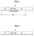
- FIG. 4 shows an example 40 of print data sent from a host. It indicates that characters A and B of an ANK character set represented in hexadecimal code are printed in spacing of a predetermined amount (represented by ESC/P of a standard printer control code system most frequently used in serial printers). The spacing between the characters A and B is specified in 36/120 inches, Assuming that the printer is set to the above-mentioned very high speed mode (90 dpi) when it receives the instruction,
- FIG. 5 shows a print data example different from the example in FIG. 4 only in character spacing.
- the spacing between characters A and B is specified in 31/120 inches. In this case, when an attempt is made to convert the denominator of 31/120 into 90,
- a way can be designed to print at high speed in low resolution even if a printer receives a print instruction containing position specification data of different resolution from that set as the print quality of the printer; such an idea is not involved in the conventional serial printers.
- a printer for solving the problem is a printer for enabling the user to select one of print densities, as described below:
- a printer comprising an image buffer for storing unprinted data in a bit image format and a print instruction conversion section for interpreting a received print instruction and executing bit image expansion in the image buffer in the density responsive to the print density selected in the printer. That is, when the printer is set to a print density of 90 dpi, basically bit image expansion is executed in 90 dpi.
- the print instruction conversion section converts the shift distance into that of the selected print density and represents in the image buffer.
- a line buffer for dividing a received print instruction for each piece of information concerning one-line print scanning which is retained thereby. If print information with the print density selected by the printer and print-position specification information with a shift distance in any other density than selected are mixed in the information concerning one-line print scanning retained in the line buffer, the print instruction conversion section converts the shift distance into the selected print density.
- error correction means for correcting an error occurring when the print instruction conversion section converts the shift distance into that of the print density. That is, if the print density conversion causes an error to occur between the shift distance, being represented by the print-position specification information, and a shift distance, being represented by bit image data expanded in the image buffer, error correction means is included.
- the specific error correction means may be configured as follows: For example, error information is prepared by performing the following calculation: The shift distance of a conversion source represented with a dot pitch value as the denominator and the number of dots as the numerator is multiplied by the dot pitch value of the current print density selected in the printer. If the calculation result does not become an integer, it is recognized that an error occurs. In this case, in the fraction of the calculation result, the integer value part found by dividing the numerator by the denominator is output as the number of dots representing the shift distance of a conversion destination and the remainder found by dividing the numerator by the denominator is output as an error amount.
- Engine control means reads the error correction information on bit image and drives a print engine, particularly a print head is controlled based on the error correction information.
- the error correction information is recognized as print data in error and is printed on actual paper, it is inconvenient.
- an area where print information does not exist is provided on the bit image data expanded in the image buffer, and the error correction information is stored in the area where print information does not exist.
- printing is executed at predetermined print speed with mixed data different in print density in the main scanning direction of a printer, as seen from the description that follows.
- a printer 1 is a dot matrix printer of a nine-pin head configuration
- the print density is set to 90 dpi
- characters A and B are printed with a 31/120-inch spacing therebetween as described in [Related Art].
- FIG. 1 is a block diagram to show the hardware configuration of the printer 1 of the embodiment.
- the printer 1 has a power mechanism section consisting of a paper feeder 3 for supplying paper to the inside of the printer, a print engine 20 for printing, and a paper discharge feeder 4 for discharging paper to the outside of the printer.
- the mechanism section of the printer is controlled by a printer control section made of a computer consisting of a CPU (central processing unit) 5, ROM (read-only memory) 6, and RAM (random access memory) 7.
- the printer control section is connected to a host 2 though an interface unit 9 and controls the parts of the mechanism section for performing actual print operation in accordance with a printer control language sent from the host 2.
- a control panel 8 enables the user to select quality responsive to print speed, as he or she desires, for setting a print density.
- the printer 1 of the embodiment When the printer 1 of the embodiment is set to a standard image quality mode, it prints in 240 dpi; when the printer 1 is set to a high speed mode, it prints in 120 dpi; and when the printer 1 is set to a very high speed mode, it prints in 90 dpi.
- the print density may be set and changed by a utility function of a printer driver from the host 2 and the print density setting may be stored in the printer 1.
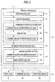
- FIG. 2 is a functional block diagram of the printer control section provided by the CPU 5 which executes an application program stored in the ROM 6.
- Printer controller 10 in the embodiment has features different from those in related art in that it has a function of converting a print instruction sent in the print density specified by the host 2 into the print density set in the printer by a command interpretation section 13 and a bit image data preparation section 14 and a function of driving and controlling a print head 21 in the print engine 20 by an engine control section 15 in accordance with the density as the conversion result and correction information.
- a line buffer data preparation section 131 of the command interpretation section 13 divides data once stored in a reception buffer 12 for each piece of information concerning one-line print scanning and places the divided data in a line buffer 132 of a data retention function assigned to a predetermined address in the RAM 7. If print information represented in the current print density selected in the printer and print-position specification information with a shift distance represented in any density other than the selected density are mixed in the information concerning the one-line print scanning retained in the line buffer 132, a correction data operation section 133 converts the density into that set in the printer and prepares error correction information according to a procedure described later with reference to FIG. 7.
- the bit image data preparation section 14 represents move information of the print head (and a carriage with the head) represented in the density resulting from the conversion as blank bits on a bit image and represents error correction information at a predetermined position on the bit image.
- the engine control section 15 reads the error correction information from bit image data expanded in an image buffer in a correction data recognition section 151 and drives a carriage motor 22 so as to cause the head to move as much as the correction in a drive control section 152.
- FIG. 3 shows a print image expanded in bit image also containing the above-mentioned error correction information.
- FIG. 3A represents the correspondence at the print density conversion time at the upper stage.
- the print image expanded in bit image at the lower stage of FIG. 3A represents an image expanded in 90 dpi corresponding to a dot matrix printer having a nine-pin head. To handle the nine-pin head, a two-byte area is provided in the vertical direction.
- An ANK character is represented 7 (vertical) X 5 (horizontal) dots, but there is a possibility that the first to ninth vertical dots may be used as an image in response to a character attribute of underline, double specification, etc. However, the remaining seven dot lines are reserved as an always unused area, namely, an area where print information cannot exist.
- FIG. 3B is an enlarged view of part 42 surrounded by the alternate long and short dash line in FIG. 3A.
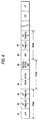
- FIG. 6 shows the contents of data retained in the line buffer 132 when the printer 1 of the embodiment receives a print instruction (instruction 50 shown in FIG. 5 plus character attribute information).
- the line buffer data preparation section 131 divides the stored print instruction for each piece of information concerning one-line print scanning and places the divided parts in the line buffer 132.
- the first three data pieces 61 to 63 of the data placed in the line buffer represent character A and its character attributes, namely, enlargement specification, reduction specification, double specification, longitudinal double size specification, etc. Therefore, in this section, there is no problem in expanding in the image buffer in 90 dpi set in the printer.
- Data 64 represents a space shift distance from the character A and data 65 represents a space recognition bit. At this time, data is sent from the host irrespective of the print density set in the printer (90 dpi), thus the shift distance is set based on the premise that the print density is 120 dpi.
- Data 66 represents character B, followed by subsequent data and a line feed.
- the correction data operation section 133 performs operation on the data 64 to convert the shift distance represented in 120 dpi into that in 90 dpi and also finds an error caused by the conversion.
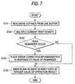
- FIG. 7 is a flowchart to show the procedure.
- the shift distance 64 "31/120 inches" placed in the line buffer 132 is read at step S101. It is multiplied by the value of the current print density set in the printer 1, 90, at step S102.
- FIG. 3A and FIG. 3B an enlarged view of a part of FIG. 3A, show the relationship.
- the 31-dot length in 120 dpi is slightly longer than the 23-dot length in 90 dpi. That is, it becomes necessary to extra move the head as much as an error 43 in FIG. 3B.
- Information to correct the error is sent from the correction data operation section 133 to the bit image data preparation section 14, which then writes an error correction information bit 44 into a lower-dots part on image data 41 expanded in bit image in accordance with the information sent from the correction data operation section 133 at step S104.
- the lower-dots part is an area where normal image data is not expanded.
- the one error correction information bit responsive to the remainder 1 corresponds to "0.25/90 inches,” namely, "1/360 inches.” If the shift distance shown in FIG. 5 is "ESC ⁇ 32/120,”
- the remainder in the embodiment takes any value of 0 to 3. Whenever the error correction information added in response to the value of the remainder is added one bit, an additional shift distance of "1/360 inches" is added according to a procedure described later with reference to FIG. 8.
- a 23-dot blank area (23 is the interger value found by the correction data operation section 133) is expanded on the bit image 41 at step S105.
- a 24-dot blank area is expanded; for "ESC ⁇ 34/120,” a 25-dot blank area is expanded.
- the engine control section 15 causes the print engine to perform actual printing based on the bit image data.
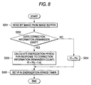
- the flowchart shown in FIG. 8 shows a control procedure executed at this time.
- the correction data recognition section 151 reads bit image data from the image buffer at step S201 and determines whether or not error correction information exists, namely, whether or not a remainder mark exists at step S202.
- the drive control section 152 controls driving the print head based on energization period (Pi) of the head. Then, the energization period (Pi) is found by the sum of Pi0 and f(x) at step S203 where Pi0 denotes the energization period when no remainder exists and f(x) changes in response to the remainder count when a remainder exists.
- Pi0 is a fixed value and the energization period changes as much as f(x).
- the energization period is changed. That is, Pi0 changes and thus the Pi0 change needs to be considered for performing operation to find a correction amount.
- the Pi0 value is output intact as the energization period (Pi) at step S204.
- the value of the energization period (Pi) found by performing the operation is set in a timer at step S205 and the print head 21 can be driven as long as the setup time.
- the printer of the invention if data in a print density different from the print density set in the printer is sent from the host and is data concerning print position setting, printing can be continued at high speed without again executing bit image expansion or setting to high print density of the least common multiple of both densities to match the print densities with each other.
- print text data, etc. consisting only of text information and position information at very high speed.
Landscapes
- Engineering & Computer Science (AREA)
- General Engineering & Computer Science (AREA)
- Physics & Mathematics (AREA)
- General Physics & Mathematics (AREA)
- Theoretical Computer Science (AREA)
- Character Spaces And Line Spaces In Printers (AREA)
- Record Information Processing For Printing (AREA)
- Storing Facsimile Image Data (AREA)
- Accessory Devices And Overall Control Thereof (AREA)
- Dot-Matrix Printers And Others (AREA)
Applications Claiming Priority (2)
| Application Number | Priority Date | Filing Date | Title |
|---|---|---|---|
| JP15484898A JP3757621B2 (ja) | 1998-06-03 | 1998-06-03 | プリンタ |
| JP15484898 | 1998-06-03 |
Publications (3)
| Publication Number | Publication Date |
|---|---|
| EP0962325A2 true EP0962325A2 (de) | 1999-12-08 |
| EP0962325A3 EP0962325A3 (de) | 2000-10-04 |
| EP0962325B1 EP0962325B1 (de) | 2009-11-25 |
Family
ID=15593231
Family Applications (1)
| Application Number | Title | Priority Date | Filing Date |
|---|---|---|---|
| EP99110901A Expired - Lifetime EP0962325B1 (de) | 1998-06-03 | 1999-06-02 | Drucker |
Country Status (4)
| Country | Link |
|---|---|
| US (1) | US6680784B1 (de) |
| EP (1) | EP0962325B1 (de) |
| JP (1) | JP3757621B2 (de) |
| DE (1) | DE69941651D1 (de) |
Families Citing this family (6)
| Publication number | Priority date | Publication date | Assignee | Title |
|---|---|---|---|---|
| US20030081240A1 (en) * | 2001-10-30 | 2003-05-01 | Jesus Soto | Method and apparatus for adjusting print settings for a file |
| US20030126316A1 (en) * | 2001-12-27 | 2003-07-03 | Abbie Parker | System and method for print outcome notification |
| JP2004098617A (ja) * | 2002-09-12 | 2004-04-02 | Seiko Epson Corp | ドットインパクトプリンタ、ドットインパクトプリンタの制御方法、その制御方法を実行するためのプログラム、およびそのプログラムを記録した記録媒体 |
| US8273066B2 (en) * | 2003-07-18 | 2012-09-25 | Kimberly-Clark Worldwide, Inc. | Absorbent article with high quality ink jet image produced at line speed |
| WO2010065697A1 (en) * | 2008-12-03 | 2010-06-10 | Videojet Technologies Inc. | An inkjet printing system and method |
| CN111026341B (zh) * | 2019-12-18 | 2024-02-09 | 深圳市汉森软件股份有限公司 | 实现任意精度打印的精度调节方法、装置、设备及介质 |
Family Cites Families (6)
| Publication number | Priority date | Publication date | Assignee | Title |
|---|---|---|---|---|
| JPS63205257A (ja) * | 1987-02-23 | 1988-08-24 | Oki Electric Ind Co Ltd | 印刷制御装置 |
| JPH089242B2 (ja) * | 1989-12-06 | 1996-01-31 | 株式会社精工舎 | ドットプリンタの印字方法 |
| JP2844575B2 (ja) * | 1990-04-19 | 1999-01-06 | キヤノン株式会社 | 印刷装置 |
| EP0481787B1 (de) * | 1990-10-19 | 1997-01-15 | Canon Kabushiki Kaisha | Ausgabeverfahren und Gerät |
| US5502792A (en) * | 1992-08-03 | 1996-03-26 | Hewlett-Packard Company | Method for reducing pixel density along one axis of a multiple dimension image representation |
| JPH06334844A (ja) * | 1993-05-20 | 1994-12-02 | Canon Inc | データ処理方法及びそれを用いた記録装置 |
-
1998
- 1998-06-03 JP JP15484898A patent/JP3757621B2/ja not_active Expired - Fee Related
-
1999
- 1999-06-02 DE DE69941651T patent/DE69941651D1/de not_active Expired - Lifetime
- 1999-06-02 EP EP99110901A patent/EP0962325B1/de not_active Expired - Lifetime
- 1999-06-03 US US09/324,722 patent/US6680784B1/en not_active Expired - Fee Related
Also Published As
| Publication number | Publication date |
|---|---|
| EP0962325A3 (de) | 2000-10-04 |
| JP3757621B2 (ja) | 2006-03-22 |
| US6680784B1 (en) | 2004-01-20 |
| EP0962325B1 (de) | 2009-11-25 |
| DE69941651D1 (de) | 2010-01-07 |
| JPH11348381A (ja) | 1999-12-21 |
Similar Documents
| Publication | Publication Date | Title |
|---|---|---|
| US5093903A (en) | System for controlling printers having differing dot densities | |
| US5084831A (en) | Printer and printing method | |
| EP0220443B1 (de) | Verfahren zur Steuerung eines Bit-Bilddruckers | |
| US5841552A (en) | Image processed apparatus for processing images having different resolutions | |
| JPH07125374A (ja) | レイアウト表示装置 | |
| US6583892B2 (en) | Output control apparatus and output control method to recognize a drawing ability of a printer | |
| EP0962325B1 (de) | Drucker | |
| EP0194676A2 (de) | Wärmedrucker | |
| EP0388160B1 (de) | Ausgabevorrichtung | |
| JP3245239B2 (ja) | 文字パターンの発生方法及び装置 | |
| US5617525A (en) | Image outputting adaptable to various fonts | |
| EP0534723B1 (de) | Druckvorrichtung und Verfahren zum Speichern von verschiedenen Druckparameterdaten | |
| JPH0751380B2 (ja) | ページプリンタにおける印字基準位置設定方法 | |
| EP0634731B1 (de) | Ausgabevorrichtung und -verfahren unter Verwendung mehrerer Datenverarbeitungseinrichtungen | |
| JP3245270B2 (ja) | 文字処理装置及び方法 | |
| JPH0280266A (ja) | プリンタ | |
| EP0628926A1 (de) | Ausgabevorrichtung und Verfahren | |
| KR940003636B1 (ko) | 도트 프린터를 이용한 라벨 프린트 방법 | |
| JP3110879B2 (ja) | 印刷方法及び装置 | |
| JPH07104954A (ja) | プリンタ及びその制御方法 | |
| JPH0781174A (ja) | テープ印字装置 | |
| JPH0713790B2 (ja) | 文字出力方法 | |
| JP2689886B2 (ja) | ドットプリンタ装置 | |
| JP3100784B2 (ja) | 文字処理方法及びその装置 | |
| JP2683468B2 (ja) | プリンタ |
Legal Events
| Date | Code | Title | Description |
|---|---|---|---|
| PUAI | Public reference made under article 153(3) epc to a published international application that has entered the european phase |
Free format text: ORIGINAL CODE: 0009012 |
|
| AK | Designated contracting states |
Kind code of ref document: A2 Designated state(s): DE ES FR GB IT |
|
| AX | Request for extension of the european patent |
Free format text: AL;LT;LV;MK;RO;SI |
|
| PUAL | Search report despatched |
Free format text: ORIGINAL CODE: 0009013 |
|
| AK | Designated contracting states |
Kind code of ref document: A3 Designated state(s): AT BE CH CY DE DK ES FI FR GB GR IE IT LI LU MC NL PT SE |
|
| AX | Request for extension of the european patent |
Free format text: AL;LT;LV;MK;RO;SI |
|
| RIC1 | Information provided on ipc code assigned before grant |
Free format text: 7B 41J 2/51 A, 7G 06K 15/02 B |
|
| 17P | Request for examination filed |
Effective date: 20001103 |
|
| AKX | Designation fees paid |
Free format text: DE ES FR GB IT |
|
| GRAP | Despatch of communication of intention to grant a patent |
Free format text: ORIGINAL CODE: EPIDOSNIGR1 |
|
| GRAS | Grant fee paid |
Free format text: ORIGINAL CODE: EPIDOSNIGR3 |
|
| GRAA | (expected) grant |
Free format text: ORIGINAL CODE: 0009210 |
|
| AK | Designated contracting states |
Kind code of ref document: B1 Designated state(s): DE ES FR GB IT |
|
| REG | Reference to a national code |
Ref country code: GB Ref legal event code: FG4D |
|
| REF | Corresponds to: |
Ref document number: 69941651 Country of ref document: DE Date of ref document: 20100107 Kind code of ref document: P |
|
| PG25 | Lapsed in a contracting state [announced via postgrant information from national office to epo] |
Ref country code: ES Free format text: LAPSE BECAUSE OF FAILURE TO SUBMIT A TRANSLATION OF THE DESCRIPTION OR TO PAY THE FEE WITHIN THE PRESCRIBED TIME-LIMIT Effective date: 20100308 |
|
| PLBE | No opposition filed within time limit |
Free format text: ORIGINAL CODE: 0009261 |
|
| STAA | Information on the status of an ep patent application or granted ep patent |
Free format text: STATUS: NO OPPOSITION FILED WITHIN TIME LIMIT |
|
| 26N | No opposition filed |
Effective date: 20100826 |
|
| GBPC | Gb: european patent ceased through non-payment of renewal fee |
Effective date: 20100602 |
|
| REG | Reference to a national code |
Ref country code: FR Ref legal event code: ST Effective date: 20110228 |
|
| PG25 | Lapsed in a contracting state [announced via postgrant information from national office to epo] |
Ref country code: IT Free format text: LAPSE BECAUSE OF FAILURE TO SUBMIT A TRANSLATION OF THE DESCRIPTION OR TO PAY THE FEE WITHIN THE PRESCRIBED TIME-LIMIT Effective date: 20091125 |
|
| PG25 | Lapsed in a contracting state [announced via postgrant information from national office to epo] |
Ref country code: FR Free format text: LAPSE BECAUSE OF NON-PAYMENT OF DUE FEES Effective date: 20100630 |
|
| PG25 | Lapsed in a contracting state [announced via postgrant information from national office to epo] |
Ref country code: GB Free format text: LAPSE BECAUSE OF NON-PAYMENT OF DUE FEES Effective date: 20100602 |
|
| PGFP | Annual fee paid to national office [announced via postgrant information from national office to epo] |
Ref country code: DE Payment date: 20130529 Year of fee payment: 15 |
|
| REG | Reference to a national code |
Ref country code: DE Ref legal event code: R119 Ref document number: 69941651 Country of ref document: DE |
|
| REG | Reference to a national code |
Ref country code: DE Ref legal event code: R119 Ref document number: 69941651 Country of ref document: DE Effective date: 20150101 |
|
| PG25 | Lapsed in a contracting state [announced via postgrant information from national office to epo] |
Ref country code: DE Free format text: LAPSE BECAUSE OF NON-PAYMENT OF DUE FEES Effective date: 20150101 |