EP0963122B1 - Stereoskopisches bilderzeugendes System - Google Patents
Stereoskopisches bilderzeugendes System Download PDFInfo
- Publication number
- EP0963122B1 EP0963122B1 EP99303904A EP99303904A EP0963122B1 EP 0963122 B1 EP0963122 B1 EP 0963122B1 EP 99303904 A EP99303904 A EP 99303904A EP 99303904 A EP99303904 A EP 99303904A EP 0963122 B1 EP0963122 B1 EP 0963122B1
- Authority
- EP
- European Patent Office
- Prior art keywords
- fatigue
- image
- degree
- parallax
- stereoscopic
- Prior art date
- Legal status (The legal status is an assumption and is not a legal conclusion. Google has not performed a legal analysis and makes no representation as to the accuracy of the status listed.)
- Expired - Lifetime
Links
Images






Classifications
-
- H—ELECTRICITY
- H04—ELECTRIC COMMUNICATION TECHNIQUE
- H04N—PICTORIAL COMMUNICATION, e.g. TELEVISION
- H04N13/00—Stereoscopic video systems; Multi-view video systems; Details thereof
- H04N13/20—Image signal generators
- H04N13/261—Image signal generators with monoscopic-to-stereoscopic image conversion
-
- H—ELECTRICITY
- H04—ELECTRIC COMMUNICATION TECHNIQUE
- H04N—PICTORIAL COMMUNICATION, e.g. TELEVISION
- H04N13/00—Stereoscopic video systems; Multi-view video systems; Details thereof
- H04N13/10—Processing, recording or transmission of stereoscopic or multi-view image signals
- H04N13/106—Processing image signals
- H04N13/111—Transformation of image signals corresponding to virtual viewpoints, e.g. spatial image interpolation
-
- H—ELECTRICITY
- H04—ELECTRIC COMMUNICATION TECHNIQUE
- H04N—PICTORIAL COMMUNICATION, e.g. TELEVISION
- H04N13/00—Stereoscopic video systems; Multi-view video systems; Details thereof
- H04N13/10—Processing, recording or transmission of stereoscopic or multi-view image signals
- H04N13/106—Processing image signals
- H04N13/122—Improving the three-dimensional [3D] impression of stereoscopic images by modifying image signal contents, e.g. by filtering or adding monoscopic depth cues
-
- H—ELECTRICITY
- H04—ELECTRIC COMMUNICATION TECHNIQUE
- H04N—PICTORIAL COMMUNICATION, e.g. TELEVISION
- H04N13/00—Stereoscopic video systems; Multi-view video systems; Details thereof
- H04N13/10—Processing, recording or transmission of stereoscopic or multi-view image signals
- H04N13/106—Processing image signals
- H04N13/144—Processing image signals for flicker reduction
-
- H—ELECTRICITY
- H04—ELECTRIC COMMUNICATION TECHNIQUE
- H04N—PICTORIAL COMMUNICATION, e.g. TELEVISION
- H04N13/00—Stereoscopic video systems; Multi-view video systems; Details thereof
- H04N13/30—Image reproducers
- H04N13/356—Image reproducers having separate monoscopic and stereoscopic modes
- H04N13/359—Switching between monoscopic and stereoscopic modes
-
- H—ELECTRICITY
- H04—ELECTRIC COMMUNICATION TECHNIQUE
- H04N—PICTORIAL COMMUNICATION, e.g. TELEVISION
- H04N13/00—Stereoscopic video systems; Multi-view video systems; Details thereof
- H04N13/10—Processing, recording or transmission of stereoscopic or multi-view image signals
- H04N13/189—Recording image signals; Reproducing recorded image signals
-
- H—ELECTRICITY
- H04—ELECTRIC COMMUNICATION TECHNIQUE
- H04N—PICTORIAL COMMUNICATION, e.g. TELEVISION
- H04N13/00—Stereoscopic video systems; Multi-view video systems; Details thereof
- H04N13/10—Processing, recording or transmission of stereoscopic or multi-view image signals
- H04N13/194—Transmission of image signals
-
- H—ELECTRICITY
- H04—ELECTRIC COMMUNICATION TECHNIQUE
- H04N—PICTORIAL COMMUNICATION, e.g. TELEVISION
- H04N13/00—Stereoscopic video systems; Multi-view video systems; Details thereof
- H04N13/30—Image reproducers
- H04N13/332—Displays for viewing with the aid of special glasses or head-mounted displays [HMD]
-
- H—ELECTRICITY
- H04—ELECTRIC COMMUNICATION TECHNIQUE
- H04N—PICTORIAL COMMUNICATION, e.g. TELEVISION
- H04N13/00—Stereoscopic video systems; Multi-view video systems; Details thereof
- H04N13/30—Image reproducers
- H04N13/361—Reproducing mixed stereoscopic images; Reproducing mixed monoscopic and stereoscopic images, e.g. a stereoscopic image overlay window on a monoscopic image background
-
- H—ELECTRICITY
- H04—ELECTRIC COMMUNICATION TECHNIQUE
- H04N—PICTORIAL COMMUNICATION, e.g. TELEVISION
- H04N13/00—Stereoscopic video systems; Multi-view video systems; Details thereof
- H04N2013/0074—Stereoscopic image analysis
- H04N2013/0081—Depth or disparity estimation from stereoscopic image signals
-
- H—ELECTRICITY
- H04—ELECTRIC COMMUNICATION TECHNIQUE
- H04N—PICTORIAL COMMUNICATION, e.g. TELEVISION
- H04N13/00—Stereoscopic video systems; Multi-view video systems; Details thereof
- H04N2013/0074—Stereoscopic image analysis
- H04N2013/0085—Motion estimation from stereoscopic image signals
-
- H—ELECTRICITY
- H04—ELECTRIC COMMUNICATION TECHNIQUE
- H04N—PICTORIAL COMMUNICATION, e.g. TELEVISION
- H04N2213/00—Details of stereoscopic systems
- H04N2213/002—Eyestrain reduction by processing stereoscopic signals or controlling stereoscopic devices
Definitions
- the present invention relates to visual image systems and, more particularly, relates to a visual image system in which the degree of three-dimensionality is controlled by estimating effects produced on the observer based on video signals.
- the delay amount for generating subordinate video signal is then determined on the basis of an extent of motion and an image switching means for inputting the main or subordinate video signal is regulated depending on the direction of the motion, thereby providing an output with determining which one of the main or subordinate video signal is outputted as a left-eye video signal or a right-eye video signal.
- a disclosure has been made with respect to technique for converting a two-dimensional visual image into a three-dimensional visual image in which a first phase-shifted visual image of which horizontal phase is gradually delayed by each one field along a vertical direction is produced based on a two-dimensional input image and a second phase-shifted visual image of which horizontal phase is gradually advanced by each one field along the vertical direction is produced based on the input image.
- One of the first phase-shifted and second phase-shifted images is used as a visual image for the left eye and the other is used for a visual image for the right eye.
- Japanese patent application laid open No.9-23451 discloses an apparatus for controlling stereoscopic condition as follows.
- a disclosure has been made with respect to a controlling apparatus in which: a sensor for detecting the temperature of skin at the forehead and a sensor for detecting the temperature of skin at the nose are set on glasses for viewing stereoscopic images so that a measure of excitation is provided from an excitation measure data converter based on their detected outputs; and a sensor for detecting blink is set on the glasses for viewing stereoscopic images so that a measure of fatigue is provided based on its detected output.
- a measure of enhancement on three-dimensionality is then outputted from a stereoscopic enhancement controlling circuit based on the degree of excitation and the degree of fatigue.
- the delay amount at a field memory of the stereoscopic television receiver for effecting 2D/3D conversion is controlled depending on this stereoscopic enhancement measure, thereby making it possible to control to a stereoscopic condition which is desirable according to the user's sensitivity.
- control buttons for adjusting a parallax are provided on a control panel for operating a game machine capable of giving a three-dimensional sensation to a game player.
- the three-dimensional sensation becomes gradually less intense each time a first control button is depressed and becomes more intense each time a second control button is depressed.
- a visual image system comprising:
- a visual image system comprising:
- the degree of fatigue produced on the observer is thus estimated from inputted video signal and, on the basis of such fatigue measure estimating quantity, the degree of three-dimensionality of stereoscopic image is restrained or switching from stereoscopic image to two-dimensional image is regulated. It is thereby possible to achieve a visual image system in which stereoscopic image can be suitably controlled so as not to produce such effects as fatigue on the observer without any biological measurement on the observer. The above main object is thereby accomplished.
- said three-dimensionality control means comprises means for regulating switching of stereoscopic image to be presented to the observer to two-dimensional image based on a fatigue measure estimating quantity obtained at the fatigue measure estimating means.
- a visual image system including: fatigue measure estimating means for estimating from inputted video signal the degree of fatigue produced on an observer; and display controlling means for controlling displaying method of visual image to be presented to the observer based on a fatigue measure estimating quantity obtained at the fatigue measure estimating means.
- the degree of fatigue produced on the observer is thus estimated from inputted video signal and the displaying method of visual image is controlled on the basis of such fatigue measure estimating quantity. It is thereby possible to achieve a visual image system in which a suitable control on displaying method of visual image such as switching of stereoscopic image to two-dimensional image or restraining of parallax quantity for the purpose of not producing such effects as fatigue on the observer can be effected also without any biological measurement on the observer.
- Fig.1 is a schematic block diagram showing a first embodiment of the visual image system according to the present invention.
- numeral 1 is a three-dimensional image reproducer for transmitting three-dimensional video signal; 2, a parallax quantity detecting section for detecting a parallax quantity in three-dimensional video signal outputted from the three-dimensional image reproducer 1; 3, a fatigue measure estimating section for estimating a fatigue measure based on the parallax quantity detected at the parallax quantity detecting section 2; 4, a 3D/2D image switching section for providing output by switching between three-dimensional video signal and two-dimensional video signal in accordance with an image switching signal which is provided on the basis of the estimation of fatigue measure; 5, an image display section for displaying a three-dimensional image or a two-dimensional image outputted by the image switching section 4.
- 3D image represents a three-dimensional image
- 2D image represents a two-dimensional image.
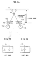
- Fig.2A shows the manner of observing a three-dimensional (stereoscopic) image where a sphere appears as jutting out, in which: denoted by numerals lla and 11b are the left and right eyes, respectively; 12 is a lens disposed immediately in front of the left and right eyes; and 13a and 13b are a left-eye LCD visual image display section and a right-eye LCD visual image display section, respectively, located adjacent to the lens 12, on which the visual images shown in Figs.2B and 2C are displayed, respectively.
- mark ⁇ represents an image at infinity and mark O represents a sphere which is displayed three-dimensionally (in a jutting out manner).
- XL represents the horizontal position of the sphere in the left-eye image
- XR represents the horizontal position of the sphere in the right-eye image, these being not equal to each other in value and shifted toward the right or toward the left from their median.
- Fig.2A what is denoted by numeral 15 is a virtual image position at which the sphere viewed by the left and right eyes is displayed, the eyes being focused on this position.
- Denoted by numeral 14 is a fusion image position at which the two images at the virtual image position 15 are viewed as one image by the two eyes.
- the distance from the position of lens 12 to the fusion image position 14 is referred to as a convergence distance and the distance from the position of lens 12 to the virtual image position 15 is referred to as a visual range.
- the parallax quantity represented by the difference in horizontal position between the left and right images (XL-XR), is in conformity with the convergence distance so that a larger parallax quantity means a greater jutting out toward the observer.
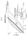
- the 45-degree solid line at the center represents the portion of complete correspondence between convergence and accommodation, the vicinity thereof indicating a range which is allowable for example due to depth of focus.
- the range somewhat varies depending on the adopted reference for allowance, i.e., visual acuity ( ⁇ :5 ⁇ ) or blur detectivity ( ⁇ :15 ⁇ ).
- the curves on the outer sides represent fusion image limit of the two eyes: the solid lines through black dots represent a maximum fusion image limit; the dotted lines represent the range in which a fusion image is established again from a condition of double images; and the dashed lines represent a fusion image limit when the image displaying time is 0.5 sec.
- a disclosure is made therein that a feeling of exhaustion is caused by a prolonged observation of a dynamic image unless it is a stereoscopic reproduction within the dashed-line range.
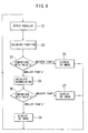
- a parallax "p" is detected from the left and right three-dimensional video signals (step S1).
- a function value for estimating the fatigue measure is then calculated based on the detected parallax "p" (step S2). This function calculation is performed by considering the influence (fatigue) produced on the observer's eye by a parallax in the stereoscopic image.
- a measure of such influence on the eye may be obtained from the diagram shown in Fig.3 , showing a correspondence between convergence (parallax) and accommodation (visual range) and their allowable range. It is indicated in Fig.3 that: the larger the difference between convergence (parallax) and accommodation (visual range) the greater the degree of influence (fatigue measure) produced on the eye.
- a function is formed as shown in the following equation (1) where an increase in ("visual range" - "parallax”) results in a nonlinear increase in the influence measure.
- ⁇ Influence measure ⁇ ⁇ ⁇ ⁇ Visual range ⁇ - ⁇ Parallax ⁇ 2 + ⁇ ⁇ ⁇ Visual range ⁇ - ⁇ Parallax ⁇ + ⁇
- the value of influence measure f(p) obtained by the above function calculation is compared with an allowable limit value "a" of convergence (fusion image) (for example the solid lines through the black dots in Fig.3 ) at which visual images may be recognized as a stereoscopic image (step S3).
- This allowable convergence limit value "a” may be regarded as an allowable fatigue limit value. If the value of influence measure f(p) obtained by the function calculation based on parallax is greater than the allowable convergence limit value "a”, the system is switched to display a two-dimensional image (step S4). If the value of influence measure f(p) is smaller than the allowable convergence limit value "a", a time accumulation of the value of influence measure f(p) is calculated (step S5).
- the accumulated calculation value of the influence measure value f(p) obtained by the function calculation based on parallax is then compared with an allowable accumulated convergence limit value "b" (step S6).
- This allowable accumulated convergence limit value "b” may be regarded as an allowable accumulated fatigue limit value and may be previously set by the maker of the apparatus, be individually adjusted and set by the user or be set by the user in accordance with the degree of fatigue when actually used. If the allowable accumulation convergence limit value "b” has been exceeded, the system is switched to display a two-dimensional image (step S7). If the allowable accumulation convergence limit value "b” has not been exceeded, the three-dimensional (stereoscopic) visual image is displayed as it is (step S8) and the above operation is executed in repetition.
- the system is automatically switched to a two-dimensional image when a three-dimensional image exceeding the fusion image limit has been received for a short time period, and it goes back to display a stereoscopic image upon returning of a visual image of a lesser influence measure. If, then, fatigue has been accumulated and exceeded the limit value as a result of observing three-dimensional image for a long time period, the system is automatically switched to a two-dimensional image and, thereafter, a two-dimensional image is to be observed.
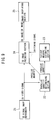
- the parallax quantity detecting section 2 is constituted by a correlation calculating section 2-1 at which a parallax signal "p" is obtained by performing a correlation calculation of the left and right video signals.
- the fatigue measure estimating section 3 includes a function calculating section 3-1 which receives the parallax signal "p" outputted from the parallax quantity detecting section 2 and provides a corresponding value of the function f(p) of influence measure (fatigue measure).
- An actual function calculation is not performed at the function calculating section 3-1, but it includes a table within a ROM so that, when a value of the parallax signal " p" has been inputted, a value of f(p) matching the corresponding influence measure (fatigue measure) is read out.
- the fatigue measure estimating section 3 further includes: a first comparison section 3-2 for receiving the value of function f(p) outputted from the function calculating section 3-1 and comparing it with the above described allowable convergence limit value "a"; and an accumulation calculating section 3-3 for also receiving the value of function f(p) outputted from the function calculating section 3-1 and calculating the time accumulation of such value f(p).
- the fatigue measure estimating section 3 furthermore includes a second comparison section 3-4 for comparing the accumulated value outputted from the accumulation calculating section 3-3 with the above described allowable accumulated convergence limit value "b".
- a signal for switching the stereoscopic image to a two-dimensional image is continuously transmitted when the accumulated value from the accumulation calculating section 3-3 has exceeded the allowable accumulated convergence limit value "b".
- Fig.6 is a block diagram showing the second embodiment, where like components as in the first embodiment shown in Fig.1 are denoted by like numerals.
- a parallax quantity changing section 6 is provided instead of the 3D/2D image switching section 4 in the first embodiment.
- a restrained stereoscopic video signal is provided with changing the parallax quantity (three-dimensionality) in stereoscopic video signal to a restrained parallax quantity, i.e., a target parallax quantity (restrained three-dimensionality) at which for example fatigue is not caused even after an uninterrupted observation, based on an output signal (parallax restraining signal) from a first comparison section, of the fatigue measure estimating section 3 of the same construction as that in the first embodiment shown in Fig.5 , where a value of function f(p) corresponding to parallax is compared with the allowable convergence limit value "a" and based on an output signal (parallax restraining signal) from a second comparison section where the accumulated calculation value of function f(p) corresponding to parallax is compared with the allowable accumulated convergence limit value "b".
- This target parallax quantity corresponds to the value at which accumulated fatigue due to an uninterrupted observation is allowable, i.e
- Figs.7A and 7B represent the left-eye image and right-eye image that are based on a stereoscopic video signal from the three-dimensional image reproducer.
- the parallax quantity (XL-XR) of these images the left-eye image shown in Fig.7A as a whole is shifted toward the left and the right-eye image shown in Fig.7B as a whole is shifted toward the right so as to change them as shown in Figs.7C and 7D .
- This shifting amount is the parallax restraining quantity.
- the parallax quantity (XL'-XR') becomes smaller so that a stereoscopic image is obtained as of the parallax quantity (three-dimensionality) at which fatigue is not caused even after an uninterrupted observation.
- shifting of the left and right images toward different directions from each other is shown as the technique for restraining parallax quantity.
- Other techniques for restraining the degree of three-dimensionality include a technique in which a compression of depth is effected.
- a relative depth of the object is inferred for example from the contrast in image and a three-dimensional visual image is generated by imparting a distortion to the image correspondingly to such depth.
- a stereoscopic image is generated by imparting a distortion [corresponding to parallax (XL-XR)] so that the position of the sphere is different between the left-eye image and the right-eye image as shown in Fig.8B .
- a visual image is generated as shown in Fig.8C in which the amount of distortion of the sphere is restrained. It is thereby possible to obtain a stereoscopic image of which the degree of three-dimensionality is restrained by compressing the depth thereof.
- the amount of distortion [parallax quantity (XL'-XR')] at this time is desirably a distortion amount within ⁇ 0.5 diopter (D) of visual range (accommodation) as also can be seen from the diagram of correspondence in Fig.3 .
- a further visual image system which does not form part of the present invention, will now be described.
- a three-dimensional image is generated by setting a parallax quantity (delay amount) according to the extent of motion in the two-dimensional image.
- the further visual image system is adapted to form a 2D/3D image switching signal at a fatigue measure estimating section on the basis of the parallax quantity set in such technique.
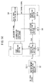
- Fig.9 is a block diagram showing the further visual image system, which does not form part of the present invention, including: 21, a two-dimensional image reproducer; 22, a parallax quantity determining section for determining the parallax quantity based on the extent of motion in the two-dimensional video signal from the two-dimensional image reproducer 21; and 23, a fatigue measure estimating section of the same construction as the fatigue measure estimating section in the first and second embodiments shown in Figs.1 and 6 , receiving a parallax quantity from the parallax quantity determining section 22 and transmitting a 2D/3D image switching signal.
- What is denoted by numeral 24 is a three-dimensional image generating section for receiving the parallax quantity set at the parallax quantity determining section 22 and transforming a two-dimensional image into a three-dimensional image
- 25 is a visual image display section for displaying a three-dimensional image from the three-dimensional image generating section 24 or a two-dimensional image.
- the parallax (XL-XR) between the three-dimensional left and right images as shown in Fig.10A is gradually reduced to those shown in Fig.10B and 10C .
- a third embodiment will now be described.
- motion vectors in the image are detected and the three-dimensional image is switched to a two-dimensional image on the basis of such motion vectors. It is generally said that a visual image involving a vigorous motion produces a greater influence on the observer.
- the present embodiment is made to eliminate an occurrence of such phenomenon.
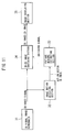
- Fig.11 is a block diagram showing the third embodiment, including: 31, a three-dimensional image reproducer; 32, an image motion detecting section for detecting motion vectors in a three-dimensional video signal outputted from the three-dimensional image reproducer 31; 33, a fatigue measure estimating section for estimating the degree of fatigue based on the motion vectors detected at the image motion detecting section 32; 34, a 3D/2D image switching section for providing an output by switching between three-dimensional video signal and two-dimensional video signal according to a switching signal which is provided on the basis of an estimation of fatigue measure; and 35, a visual image display section for displaying a three-dimensional image or a two-dimensional image provided from the image switching section 34.
- FIG.12A An example of detection of motion vector at the image motion detecting section 32 will now be described by way of Figs.12A to 12C .
- the background is being moved to the left as shown in Figs.12A and 12B .
- motion vectors as shown in Fig.12C are detected and, for example, an average of these values is inputted to the fatigue measure estimating section 33.
- a motion vector "m" is detected from a stereoscopic video signal (step S11).
- a function calculation for estimating the degree of fatigue is then performed on the basis of the detected motion vector "m” (step S12). This function calculation is performed by considering the influence (fatigue) produced on the eye of the observer by the image motion in the stereoscopic image.
- the value f(m) obtained by the above described function calculation is then compared with an allowable limit value "a" (step S13). If the value f(m) obtained by the function calculation based on the motion vectors is greater than the allowable limit value "a", the system is switched to display a two-dimensional image (step S14).
- step S15 a time accumulation is calculated of the function value f(m) (step S15).
- the calculated value of accumulation of value f(m) obtained by the function calculation based on the motion vectors is then compared with an allowable accumulation limit value "b" (step S16). If the calculated value of accumulation of the function calculation value f(m) has exceeded the allowable accumulation limit value "b”, the system is switched to display a two-dimensional image (step S17). If it is smaller than the allowable accumulation limit value "b", the three-dimensional (stereoscopic) image is displayed as it is (step S18) and the above operation is executed in repetition.
- the image motion detecting section 32 is constituted by a motion amount calculating section 32-1 for computing the motion vector "m" from a stereoscopic video signal.
- the fatigue measure estimating section 33 includes a function calculating section 33-1 for receiving motion vector "m” provided from the image motion detecting section 32 and outputting a corresponding function value f(m).
- an actual function calculation is not performed at the function calculating section 33-1, but it includes a table within a ROM so that, when a value of motion vector "m" has been inputted, a function value f(m) matching the corresponding influence measure (fatigue measure) is read out.
- the fatigue measure estimating section 33 further includes: a first comparison section 33-2 for receiving the value of function f(m) outputted from the function calculating section 33-1 and comparing it with the above described allowable limit value "a"; and an accumulation calculating section 33-3 for also receiving the value of function f(m) outputted from the function calculating section 33-1 and calculating the time accumulation of such value f(m).
- the fatigue measure estimating section 33 furthermore includes a second comparison section 33-4 for comparing the accumulated value outputted from the accumulation calculating section 33-3 with the above described allowable accumulated convergence limit value "b".
- a signal for continuously switching the stereoscopic image to a two-dimensional image is transmitted when the accumulated value from the accumulation calculating section 33-3 has exceeded the allowable accumulated convergence limit value "b".
- a parallax quantity (delay amount) is set in accordance with an extent of motion in a two-dimensional image in a similar manner to the system of Fig. 9 , and a 3D/2D image switching signal is formed at the fatigue measure estimating section by using the extent of motion in the two-dimensional image detected in generating a three-dimensional image.
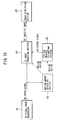
- Fig.15 is a block diagram showing the further visual image system, including: 41, a two-dimensional image reproducer; 42, a motion quantity detecting section for detecting motion vectors based on a two-dimensional video signal from the two-dimensional image reproducer 41; 43, a fatigue measure estimating section of the same construction as the fatigue measure estimating section 33 in the third embodiment shown in Fig.11 for receiving motion vectors from the motion amount detecting section 42 and transmitting a 3D/2D image switching signal.
- What is denoted by numeral 44 is a three-dimensional image generating section for receiving the motion vectors detected at the motion quantity detecting section 42 and transforming a two-dimensional image into a three-dimensional image
- 45 is a visual image display section for displaying the three-dimensional image from the three-dimensional image generating section 44 or a two-dimensional image.
- the degree of influence produced on the observer is estimated from inputted video signal and the three-dimensionality of stereoscopic image is restrained or a stereoscopic image is switched to a two-dimensional image on the basis of such influence measure estimating quantity, it is possible to achieve a visual image system in which a stereoscopic image can be suitably controlled so as not to produce such effects as fatigue on the observer without any biological measurement on the observer.
- the degree of influence produced on the observer is estimated from inputted video signal and display method of image is controlled on the basis of such influence measure estimating quantity, it is possible to achieve a visual image system in which the display method of image such as switching of stereoscopic image to two-dimensional image or restraining of parallax quantity can be suitably controlled so as not to produce such effects as fatigue on the observer also without any biological measurement on the observer.
Landscapes
- Engineering & Computer Science (AREA)
- Multimedia (AREA)
- Signal Processing (AREA)
- Testing, Inspecting, Measuring Of Stereoscopic Televisions And Televisions (AREA)
- Processing Or Creating Images (AREA)
Claims (5)
- Optisches Bildsystem, das Folgendes umfasst:ein Ermüdungsmaß-Abschätzmittel (3), das dazu ungeordnet ist, aus einem eingegebenen stereoskopischen Videosignal den an einem Beobachter erzeugten Ermüdungsgrad als eine infolge des Unterschieds zwischen Parallaxe und Sichtweite auftretende Ermüdung der Augen basierend auf einem in Bildern vom genannten eingegebenen stereoskopischen Videosignal erkannten Parallaxenbetrag abzuschätzen, und einen Grad akkumulierter Ermüdung durch Berechnen der Zeitakkumulation des genannten Ermüdungsgrads zu bestimmen; undein Dreidimensionalitäts-Steuermittel (4, 6), das dazu angeordnet ist, wenn der genannte Grad akkumulierter Ermüdung einen vorherbestimmten Schwellenwert ("b") überschreitet, die Parallaxe im genannten stereoskopischen Videosignal basierend auf dem, am genannten Ermüdungsmaß-Abschälzmittel (3) ermittelten genannten Ermüdungsgrad zu reduzieren, wobei die genannte Parallaxe den Grad der Dreidimensionalität eines dem Beobachter darzubietenden stereoskopischen Bilds repräsentiert.
- Optisches Bildsystem, das Folgendes umfasst:ein Ermüdungsmaß-Abschätzmitttel (33), das dazu angeordnet ist, aus einem eingegebenen stereoskopischen Videosignal den an einem Beobachter erzeugten Ermüdungsgrad als eine infolge einer zeitweiligen Bewegung auftretende Ermüdung der Augen, basierend auf einem in Bildern vom genannten eingegebenen stereoskopischen Videosignal erkannter Bewegungsvektor, durch Erkennen des zeitweiligen Bewegungsbetrags in den genannten Bildern abzuschätzen und einen Grad akkumulierter Ermüdung durch Berechnen der Zeitakkumulation des genannten Ermüdungsgrads zu bestimmen; undein Dreidimensionalitäts-Steuermittel (34), das dazu angeordnet ist, wenn der genannte Grad akkumulierter Ermüdung einen vorherbestimmten Schwellenwert ("b") überschreitet, die Parallaxe im genannten stereoskopischen Videosignal basierend auf dem, am genannten Ermüdungsmaß-Abschätzmittel (33) ermittelten genannten Ermüdungsgrad zu reduzieren, wobei die genannte Parallaxe den Grad der Dreidimensionalität eines dem Beobachter darzubietenden stereoskopischen Bilds repräsentiert.
- Optisches Bildsystem nach Anspruch 1 oder Anspruch 2, wobei das genannte Dreidimensionalitäts-Steuermittel (4. 6. 34) ein Mittel (4, 34) zum Regeln des Umschaltens eines einem Beobachter darzubietenden stereoskopischen Bilds zu einem zweidimensionalen Bild basierend auf einem am Ermüdungsmaß-Abschätzmittel (3) ermittelten Ermüdungsgrad umfasst.
- Optisches Bildsystem nach Anspruch 3, wobei das genannte Mittel (4, 34) zum Regeln des Umschaltens von Bildern das Umschalten von einem stereoskopischen Bild zu einem zweidimensionalen Bild regelt, während es die Parallaxe des stereoskopischen Bilds gleichmäßig ohne Unterbrechung ändert.
- Optisches Bildsystem nach einem der Ansprüche 1 bis 4, wobei das genannte Ermüdungsmaß-Abschätzsystem (3) die Zeitakkumulation des am Beobachter erzeugten Ermüdungsgrads durch ein Zeitintegral desselben abschätzt.
Applications Claiming Priority (2)
| Application Number | Priority Date | Filing Date | Title |
|---|---|---|---|
| JP17053198 | 1998-06-04 | ||
| JP17053198A JP4149037B2 (ja) | 1998-06-04 | 1998-06-04 | 映像システム |
Publications (3)
| Publication Number | Publication Date |
|---|---|
| EP0963122A2 EP0963122A2 (de) | 1999-12-08 |
| EP0963122A3 EP0963122A3 (de) | 2002-06-26 |
| EP0963122B1 true EP0963122B1 (de) | 2010-12-15 |
Family
ID=15906660
Family Applications (1)
| Application Number | Title | Priority Date | Filing Date |
|---|---|---|---|
| EP99303904A Expired - Lifetime EP0963122B1 (de) | 1998-06-04 | 1999-05-19 | Stereoskopisches bilderzeugendes System |
Country Status (4)
| Country | Link |
|---|---|
| US (2) | US6614927B1 (de) |
| EP (1) | EP0963122B1 (de) |
| JP (1) | JP4149037B2 (de) |
| DE (1) | DE69943034D1 (de) |
Families Citing this family (137)
| Publication number | Priority date | Publication date | Assignee | Title |
|---|---|---|---|---|
| JP2003018619A (ja) | 2001-07-03 | 2003-01-17 | Olympus Optical Co Ltd | 立体映像評価装置およびそれを用いた表示装置 |
| GB0129992D0 (en) * | 2001-12-14 | 2002-02-06 | Ocuity Ltd | Control of optical switching apparatus |
| JP3673217B2 (ja) * | 2001-12-20 | 2005-07-20 | オリンパス株式会社 | 映像表示装置 |
| JP4138747B2 (ja) * | 2002-08-27 | 2008-08-27 | シャープ株式会社 | 最適な再生モードでコンテンツを再生できるコンテンツ再生装置 |
| KR100554991B1 (ko) * | 2002-09-17 | 2006-02-24 | 샤프 가부시키가이샤 | 2d(2차원) 및 3d(3차원)표시 기능을 구비하는 전자 기기 |
| JP4145122B2 (ja) * | 2002-09-27 | 2008-09-03 | シャープ株式会社 | 立体画像表示装置 |
| JP2004165709A (ja) * | 2002-09-27 | 2004-06-10 | Sharp Corp | 立体画像表示装置、立体画像記録方法及び立体画像伝送方法 |
| CN1703915A (zh) * | 2002-09-27 | 2005-11-30 | 夏普株式会社 | 3-d图像显示单元,3-d图像记录装置和3-d图像记录方法 |
| KR100804572B1 (ko) | 2002-09-27 | 2008-02-20 | 샤프 가부시키가이샤 | 입체화상 표시장치, 입체화상 기록장치, 입체화상 부호화장치, 입체화상 복호장치, 입체화상 기록방법 및 입체화상 전송방법 |
| JP2004165710A (ja) * | 2002-09-27 | 2004-06-10 | Sharp Corp | 立体画像表示装置、立体画像記録方法及び立体画像伝送方法 |
| JP4713054B2 (ja) * | 2002-09-27 | 2011-06-29 | シャープ株式会社 | 立体画像表示装置、立体画像符号化装置、立体画像復号装置、立体画像記録方法及び立体画像伝送方法 |
| US9426490B2 (en) | 2002-11-01 | 2016-08-23 | Godo Kaisha Ip Bridge 1 | Moving picture encoding method and motion picture decoding method |
| JP2004246725A (ja) * | 2003-02-14 | 2004-09-02 | Sharp Corp | 表示装置、表示制御方法、表示制御プログラム及びこれを記録したコンピュータ読み取り可能な記録媒体 |
| JP4490074B2 (ja) * | 2003-04-17 | 2010-06-23 | ソニー株式会社 | 立体視画像処理装置、立体視画像表示装置、立体視画像提供方法、および立体視画像処理システム |
| US20040222987A1 (en) * | 2003-05-08 | 2004-11-11 | Chang Nelson Liang An | Multiframe image processing |
| WO2004107765A1 (ja) * | 2003-05-28 | 2004-12-09 | Sanyo Electric Co., Ltd. | 立体映像表示装置及びテキストデータ処理装置及びプログラム及び記憶媒体 |
| JP2004357156A (ja) * | 2003-05-30 | 2004-12-16 | Sharp Corp | 映像受信装置および映像再生装置 |
| US7411611B2 (en) * | 2003-08-25 | 2008-08-12 | Barco N. V. | Device and method for performing multiple view imaging by means of a plurality of video processing devices |
| WO2005059842A1 (es) * | 2003-12-19 | 2005-06-30 | Tdvision Corporation S.A. De C.V. | Sistema de videojuegos 3d |
| JP4665430B2 (ja) * | 2004-04-26 | 2011-04-06 | 富士ゼロックス株式会社 | 画像出力制御装置、画像出力制御方法及び画像出力制御プログラム並びにプリンタ装置 |
| EP1779676A1 (de) | 2004-08-10 | 2007-05-02 | Koninklijke Philips Electronics N.V. | Ansichtsmoduserkennung |
| CN101006733B (zh) * | 2004-08-18 | 2010-05-05 | 夏普株式会社 | 图像数据显示装置 |
| KR100861476B1 (ko) * | 2004-08-18 | 2008-10-02 | 샤프 가부시키가이샤 | 화상 데이터 표시 장치 |
| JP4602737B2 (ja) * | 2004-10-25 | 2010-12-22 | シャープ株式会社 | 映像表示装置 |
| JP4246691B2 (ja) * | 2004-11-30 | 2009-04-02 | 本田技研工業株式会社 | 画像情報処理システム、画像情報処理方法、画像情報処理プログラム、及び自動車 |
| US20060139448A1 (en) * | 2004-12-29 | 2006-06-29 | Samsung Electronics Co., Ltd. | 3D displays with flexible switching capability of 2D/3D viewing modes |
| JP4046121B2 (ja) | 2005-03-24 | 2008-02-13 | セイコーエプソン株式会社 | 立体画像表示装置及び方法 |
| JP4555722B2 (ja) * | 2005-04-13 | 2010-10-06 | 株式会社 日立ディスプレイズ | 立体映像生成装置 |
| KR100932977B1 (ko) | 2005-07-05 | 2009-12-21 | 삼성모바일디스플레이주식회사 | 입체 영상 표시 장치 |
| KR100913173B1 (ko) | 2005-07-05 | 2009-08-19 | 삼성모바일디스플레이주식회사 | 3d 그래픽 처리장치 및 이를 이용한 입체영상 표시장치 |
| US8885017B2 (en) * | 2005-07-14 | 2014-11-11 | 3Ality Digital Systems, Llc | Real-time process and technology using image processing to maintain and ensure viewer comfort during capture, live transmission, and post-production of stereoscopic 3D imagery |
| US8279221B2 (en) | 2005-08-05 | 2012-10-02 | Samsung Display Co., Ltd. | 3D graphics processor and autostereoscopic display device using the same |
| KR100739730B1 (ko) * | 2005-09-03 | 2007-07-13 | 삼성전자주식회사 | 3d 입체 영상 처리 장치 및 방법 |
| KR100739764B1 (ko) | 2005-11-28 | 2007-07-13 | 삼성전자주식회사 | 입체 영상 신호 처리 장치 및 방법 |
| CN101341760B (zh) | 2005-12-19 | 2012-12-12 | 皇家飞利浦电子股份有限公司 | 3d图像显示方法和装置 |
| KR101102004B1 (ko) * | 2005-12-30 | 2012-01-04 | 삼성전자주식회사 | 3차원 입체 영상에 대한 피로도를 정량화하는 방법 및시스템 |
| US8274448B1 (en) | 2006-03-29 | 2012-09-25 | Nvidia Corporation | Stereoscopic display system, method and computer program product |
| KR100893616B1 (ko) * | 2006-04-17 | 2009-04-20 | 삼성모바일디스플레이주식회사 | 전자 영상 기기, 2d/3d 영상 표시 장치 및 그 구동방법 |
| TWI331872B (en) * | 2006-12-29 | 2010-10-11 | Quanta Comp Inc | Method for displaying stereoscopic image |
| KR101313740B1 (ko) * | 2007-10-08 | 2013-10-15 | 주식회사 스테레오피아 | 원소스 멀티유즈 스테레오 카메라 및 스테레오 영상 컨텐츠제작방법 |
| WO2009075495A1 (en) * | 2007-12-10 | 2009-06-18 | Samsung Electronics Co., Ltd. | System and method for generating and reproducing image file including 2d image and 3d stereoscopic image |
| BRPI0820739B1 (pt) * | 2007-12-14 | 2020-10-20 | Koninklijke Philips N.V. | método de reprodução de informação de vídeo, dispositivo de reprodução para reproduzir a informação de vídeo, sinal, e, portador de gravação |
| EP2274920B1 (de) * | 2008-05-12 | 2019-01-16 | InterDigital Madison Patent Holdings | System und verfahren zur messung von potentieller augenanspannung von bewegten stereobildern |
| KR100991804B1 (ko) * | 2008-06-10 | 2010-11-04 | 유한회사 마스터이미지쓰리디아시아 | 이동 기기용 입체영상생성칩 및 이를 이용한입체영상표시방법 |
| KR101539935B1 (ko) * | 2008-06-24 | 2015-07-28 | 삼성전자주식회사 | 3차원 비디오 영상 처리 방법 및 장치 |
| TWI527429B (zh) * | 2008-10-28 | 2016-03-21 | 皇家飛利浦電子股份有限公司 | 三維顯示系統 |
| US9122064B2 (en) | 2008-11-26 | 2015-09-01 | Nec Corporation | Display device, terminal device, and display method |
| HUE029122T2 (en) * | 2008-12-01 | 2017-02-28 | Sharp Kk | Content reproduction tool, reproduction process, program and media |
| WO2010084849A1 (ja) | 2009-01-22 | 2010-07-29 | 日本電気株式会社 | 立体映像鑑賞システム、表示システム、光シャッタおよび立体映像鑑賞方法 |
| JP5409107B2 (ja) * | 2009-05-13 | 2014-02-05 | 任天堂株式会社 | 表示制御プログラム、情報処理装置、表示制御方法、および情報処理システム |
| CN102461180B (zh) * | 2009-05-18 | 2016-01-20 | Lg电子株式会社 | 能进行3d模式选择的立体影像再现装置及方法 |
| JP4609805B2 (ja) * | 2009-05-28 | 2011-01-12 | Necカシオモバイルコミュニケーションズ株式会社 | 端末装置及びプログラム |
| JP5257248B2 (ja) * | 2009-06-03 | 2013-08-07 | ソニー株式会社 | 画像処理装置および方法、ならびに画像表示装置 |
| JP2011101229A (ja) * | 2009-11-06 | 2011-05-19 | Sony Corp | 表示制御装置、表示制御方法、プログラム、出力装置、および送信装置 |
| JP4587237B1 (ja) * | 2009-06-17 | 2010-11-24 | Necカシオモバイルコミュニケーションズ株式会社 | 端末装置及びプログラム |
| JP5249149B2 (ja) * | 2009-07-17 | 2013-07-31 | 富士フイルム株式会社 | 立体画像記録装置及び方法、立体画像出力装置及び方法、並びに立体画像記録出力システム |
| PL2460361T3 (pl) * | 2009-07-27 | 2020-11-16 | Koninklijke Philips N.V. | Przełączanie pomiędzy wideo 3d a wideo 2d |
| JP2011035592A (ja) * | 2009-07-31 | 2011-02-17 | Nintendo Co Ltd | 表示制御プログラムおよび情報処理システム |
| CN102172032A (zh) * | 2009-08-31 | 2011-08-31 | 松下电器产业株式会社 | 立体视控制装置、集成电路、立体视控制方法 |
| JP2011064894A (ja) * | 2009-09-16 | 2011-03-31 | Fujifilm Corp | 立体画像表示装置 |
| US8284235B2 (en) * | 2009-09-28 | 2012-10-09 | Sharp Laboratories Of America, Inc. | Reduction of viewer discomfort for stereoscopic images |
| JP5405264B2 (ja) * | 2009-10-20 | 2014-02-05 | 任天堂株式会社 | 表示制御プログラム、ライブラリプログラム、情報処理システム、および、表示制御方法 |
| JP4754031B2 (ja) * | 2009-11-04 | 2011-08-24 | 任天堂株式会社 | 表示制御プログラム、情報処理システム、および立体表示の制御に利用されるプログラム |
| JP2011101230A (ja) * | 2009-11-06 | 2011-05-19 | Sony Corp | 表示制御装置、表示制御方法、プログラム、出力装置、および送信装置 |
| JP5449079B2 (ja) * | 2009-12-11 | 2014-03-19 | 三菱電機株式会社 | 立体視映像視聴制限装置及び方法、立体視映像視聴制限通知装置及び方法、映像視聴装置及び方法、並びに映像視聴システム |
| US20120120207A1 (en) * | 2009-12-28 | 2012-05-17 | Hiroaki Shimazaki | Image playback device and display device |
| EP2355526A3 (de) | 2010-01-14 | 2012-10-31 | Nintendo Co., Ltd. | Computerlesbares Speichermedium mit einem Anzeigesteuerungsprogramm darauf, Anzeigesteuerungsvorrichtung, Anzeigesteuerungssystem und Anzeigesteuerungsverfahren |
| JP5505881B2 (ja) * | 2010-02-02 | 2014-05-28 | 学校法人早稲田大学 | 立体映像制作装置およびプログラム |
| GB2478164A (en) | 2010-02-26 | 2011-08-31 | Sony Corp | Calculating misalignment between a stereoscopic image pair based on feature positions |
| GB2478157A (en) * | 2010-02-26 | 2011-08-31 | Sony Corp | Method and apparatus for cutting between a first and second image sequence in a stereoscopic video |
| JP5533092B2 (ja) * | 2010-03-18 | 2014-06-25 | 株式会社リコー | 座標平面におけるデータ点分布領域の識別方法及びその識別プログラム |
| JP5454396B2 (ja) * | 2010-03-23 | 2014-03-26 | 株式会社Jvcケンウッド | 立体画像生成装置および立体画像生成方法、情報送信装置および情報送信方法 |
| EP2555525B1 (de) * | 2010-03-30 | 2017-10-25 | FUJIFILM Corporation | Abbildungsvorrichtung für ein facettenauge sowie disparitätseinstellungsverfahren und -programm dafür |
| JP2011216964A (ja) * | 2010-03-31 | 2011-10-27 | Sony Corp | 表示制御装置、表示制御方法、およびプログラム |
| CN102822886B (zh) * | 2010-04-05 | 2015-11-25 | 夏普株式会社 | 立体图像显示装置、显示系统、驱动方法、驱动装置、显示控制方法和显示控制装置 |
| KR101682205B1 (ko) * | 2010-05-03 | 2016-12-05 | 삼성전자주식회사 | 입체영상의 시청피로를 저감하는 장치 및 방법 |
| US9693039B2 (en) | 2010-05-27 | 2017-06-27 | Nintendo Co., Ltd. | Hand-held electronic device |
| US8970672B2 (en) | 2010-05-28 | 2015-03-03 | Qualcomm Incorporated | Three-dimensional image processing |
| KR101753801B1 (ko) * | 2010-06-10 | 2017-07-04 | 엘지디스플레이 주식회사 | 액정 표시장치 및 구동방법 |
| JP5186715B2 (ja) | 2010-06-14 | 2013-04-24 | 任天堂株式会社 | 表示制御プログラム、表示制御装置、表示制御方法、および、表示制御システム |
| WO2012002106A1 (ja) * | 2010-06-30 | 2012-01-05 | 富士フイルム株式会社 | 立体画像表示装置、立体画像表示方法、立体画像表示プログラム及び記録媒体 |
| JP5420076B2 (ja) * | 2010-06-30 | 2014-02-19 | 富士フイルム株式会社 | 再生装置、複眼撮像装置、再生方法及びプログラム |
| JP2012029216A (ja) * | 2010-07-27 | 2012-02-09 | Sony Corp | 再生装置、再生方法、およびプログラム |
| KR101150871B1 (ko) * | 2010-07-29 | 2012-06-13 | 연세대학교 산학협력단 | 수평 변이 및 수평 변이에 기초한 스테레오 영상의 피로도 계산 방법 및 장치 |
| TWI436636B (zh) * | 2010-08-16 | 2014-05-01 | 宏碁股份有限公司 | 三維視訊影像調整方法及裝置 |
| JP5025772B2 (ja) * | 2010-08-30 | 2012-09-12 | 株式会社東芝 | 立体視用眼鏡及び立体視映像表示システム |
| US8704879B1 (en) | 2010-08-31 | 2014-04-22 | Nintendo Co., Ltd. | Eye tracking enabling 3D viewing on conventional 2D display |
| WO2012029298A1 (ja) | 2010-08-31 | 2012-03-08 | パナソニック株式会社 | 撮影装置および画像処理方法 |
| WO2012029299A1 (ja) * | 2010-08-31 | 2012-03-08 | パナソニック株式会社 | 撮影装置、再生装置、および画像処理方法 |
| KR20120056929A (ko) * | 2010-09-20 | 2012-06-05 | 엘지전자 주식회사 | 휴대 단말기 및 그 동작 제어방법 |
| CN103392343B (zh) * | 2010-09-20 | 2016-03-09 | 联发科技(新加坡)私人有限公司 | 显示装置、显示方法与播放系统 |
| JP5263355B2 (ja) * | 2010-09-22 | 2013-08-14 | 株式会社ニコン | 画像表示装置及び撮像装置 |
| JP5530322B2 (ja) * | 2010-09-22 | 2014-06-25 | オリンパスイメージング株式会社 | 表示装置および表示方法 |
| KR101633336B1 (ko) * | 2010-10-01 | 2016-06-24 | 엘지전자 주식회사 | 이동 단말기 및 그 제어방법 |
| JP5543892B2 (ja) * | 2010-10-01 | 2014-07-09 | 日立コンシューマエレクトロニクス株式会社 | 再生装置、再生方法、表示装置、及び表示方法 |
| KR101309705B1 (ko) * | 2010-10-21 | 2013-09-17 | 도시바삼성스토리지테크놀러지코리아 주식회사 | 안경 및 이를 채용한 3d 영상표시 시스템 |
| KR101682208B1 (ko) * | 2010-10-22 | 2016-12-02 | 삼성전자주식회사 | 디스플레이 장치 및 방법 |
| US20120113235A1 (en) * | 2010-11-08 | 2012-05-10 | Sony Corporation | 3d glasses, systems, and methods for optimized viewing of 3d video content |
| JP2012103980A (ja) * | 2010-11-11 | 2012-05-31 | Sony Corp | 画像処理装置、画像処理方法及びプログラム |
| KR101732041B1 (ko) | 2010-11-19 | 2017-05-04 | 삼성디스플레이 주식회사 | 입체 영상 표시 장치 |
| KR101587623B1 (ko) | 2010-12-09 | 2016-01-21 | 한국전자통신연구원 | 시각적 피로 최소화를 지원하는 입체영상 제작시스템 및 그 방법 |
| KR101220223B1 (ko) | 2010-12-13 | 2013-01-09 | 한국전자통신연구원 | 스테레오스코픽 영상 시스템에서의 시각적 불편감 측정 장치 및 방법, 시각적 불편감 측정 방법을 실행하기 위한 프로그램이 기록된 기록매체 |
| JP2012151663A (ja) * | 2011-01-19 | 2012-08-09 | Toshiba Corp | 立体音響生成装置及び立体音響生成方法 |
| JP5417356B2 (ja) * | 2011-02-08 | 2014-02-12 | 株式会社東芝 | 映像処理装置、映像処理方法および立体映像表示装置 |
| JP2012170503A (ja) * | 2011-02-17 | 2012-09-10 | Kyoraku Sangyo Kk | 遊技機 |
| JP5351915B2 (ja) * | 2011-02-24 | 2013-11-27 | 富士フイルム株式会社 | 立体動画像処理装置および方法並びにプログラム |
| JP5664356B2 (ja) * | 2011-03-09 | 2015-02-04 | 富士通株式会社 | 生成装置および生成方法 |
| US8654181B2 (en) | 2011-03-28 | 2014-02-18 | Avid Technology, Inc. | Methods for detecting, visualizing, and correcting the perceived depth of a multicamera image sequence |
| WO2012133286A1 (ja) | 2011-03-31 | 2012-10-04 | 株式会社Jvcケンウッド | 立体画像生成装置及び立体画像生成方法 |
| JP5871113B2 (ja) * | 2011-03-31 | 2016-03-01 | 株式会社Jvcケンウッド | 立体画像生成装置、立体画像生成方法及び立体画像生成プログラム |
| JP5052683B1 (ja) * | 2011-04-19 | 2012-10-17 | 株式会社東芝 | 電子機器および映像表示方法 |
| JP6002043B2 (ja) * | 2011-04-28 | 2016-10-05 | パナソニック インテレクチュアル プロパティ コーポレーション オブ アメリカPanasonic Intellectual Property Corporation of America | 立体視強度調整装置、立体視強度調整方法、プログラム、集積回路、記録媒体 |
| KR101218723B1 (ko) * | 2011-05-09 | 2013-01-09 | 성균관대학교산학협력단 | 사용자의 시각적 피로도를 고려한 3d 영상 제공방법 |
| GB2490886B (en) * | 2011-05-13 | 2017-07-05 | Snell Advanced Media Ltd | Video processing method and apparatus for use with a sequence of stereoscopic images |
| TR201104918A2 (tr) | 2011-05-20 | 2012-12-21 | Vestel Elektroni̇k Sanayi̇ Ve Ti̇caret A.Ş. | Derinlik haritası ve 3d video oluşturmak için yöntem ve aygıt. |
| US9420259B2 (en) | 2011-05-24 | 2016-08-16 | Comcast Cable Communications, Llc | Dynamic distribution of three-dimensional content |
| US8887206B2 (en) | 2011-06-09 | 2014-11-11 | Cstereo3D, Llc | Device and method for rendering and delivering 3-D content |
| KR101779423B1 (ko) * | 2011-06-10 | 2017-10-10 | 엘지전자 주식회사 | 영상처리방법 및 영상처리장치 |
| US8879826B2 (en) * | 2011-07-05 | 2014-11-04 | Texas Instruments Incorporated | Method, system and computer program product for switching between 2D and 3D coding of a video sequence of images |
| US9402065B2 (en) | 2011-09-29 | 2016-07-26 | Qualcomm Incorporated | Methods and apparatus for conditional display of a stereoscopic image pair |
| WO2013050184A1 (en) * | 2011-10-04 | 2013-04-11 | Telefonaktiebolaget L M Ericsson (Publ) | Objective 3d video quality assessment model |
| KR20130054176A (ko) * | 2011-11-14 | 2013-05-24 | 삼성전자주식회사 | 3d 영상의 안정피로 측정 방법 및 장치 |
| US9191659B2 (en) * | 2011-11-16 | 2015-11-17 | Christie Digital Systems Usa, Inc. | Collimated stereo display system |
| WO2013081235A1 (ko) * | 2011-11-28 | 2013-06-06 | 한국과학기술원 | 3d 스테레오스코픽 영상에서 시각 피로도를 시각화하는 장치 |
| EP2801198B1 (de) * | 2012-01-04 | 2023-10-11 | InterDigital Madison Patent Holdings, SAS | Verarbeitung von 3d-bildsequenzen |
| WO2013145326A1 (ja) | 2012-03-30 | 2013-10-03 | 富士通株式会社 | 決定装置、決定プログラムおよび決定方法 |
| WO2013145860A1 (ja) * | 2012-03-30 | 2013-10-03 | ソニー株式会社 | 表示制御装置、表示制御方法およびプログラム |
| US9300942B2 (en) | 2012-10-18 | 2016-03-29 | Industrial Technology Research Institute | Method and control system for three-dimensional video playback using visual fatigue estimation |
| CN103780894B (zh) * | 2012-10-18 | 2016-02-10 | 财团法人工业技术研究院 | 具视觉疲劳估算的立体影片播放方法与控制系统 |
| KR102153606B1 (ko) | 2013-08-13 | 2020-09-08 | 삼성전자주식회사 | 동영상 콘텐트에 대한 사용자 피로도 예측 장치 및 방법 |
| JP6438408B2 (ja) * | 2013-10-24 | 2018-12-12 | キヤノン株式会社 | 情報処理装置、情報処理方法、制御装置、制御システム、制御方法、トモシンセシス撮影装置、x線撮影装置、画像処理装置、画像処理システム、画像処理方法、及び、コンピュータプログラム |
| KR101521213B1 (ko) * | 2014-06-25 | 2015-05-18 | 연세대학교 산학협력단 | 시각적 불편도 모델을 이용하여 입체 영상을 보정하기 위한 장치 및 그 방법 |
| JP2016115965A (ja) * | 2014-12-11 | 2016-06-23 | ソニー株式会社 | 医療用眼鏡型表示装、情報処理装置及び情報処理方法 |
| CN109716761B (zh) * | 2016-09-23 | 2020-12-08 | 日本电信电话株式会社 | 图像生成装置、图像生成方法以及记录介质 |
| CN108881877B (zh) * | 2017-05-12 | 2020-07-24 | 京东方科技集团股份有限公司 | 显示处理装置及其显示处理方法以及显示装置 |
| WO2019215984A1 (ja) * | 2018-05-09 | 2019-11-14 | オリンパス株式会社 | 画像処理装置及び画像生成方法 |
| US20230185090A1 (en) * | 2021-12-13 | 2023-06-15 | Miller Schuck | Eyewear including a non-uniform push-pull lens set |
Family Cites Families (17)
| Publication number | Priority date | Publication date | Assignee | Title |
|---|---|---|---|---|
| JPS62293381A (ja) * | 1986-06-11 | 1987-12-19 | Toshiba Corp | 立体画像表示装置 |
| EP0641132B1 (de) * | 1993-08-26 | 1999-04-14 | Matsushita Electric Industrial Co., Ltd. | Stereoskopischer Abtastapparat |
| JP2594235B2 (ja) | 1994-02-01 | 1997-03-26 | 三洋電機株式会社 | 2次元映像を3次元映像に変換する方法及び3次元映像信号生成装置 |
| DE69612647T2 (de) * | 1995-03-08 | 2001-10-18 | Koninklijke Philips Electronics N.V., Eindhoven | Dreidimensionales bildanzeigesystem |
| JPH0918894A (ja) * | 1995-06-26 | 1997-01-17 | Sanyo Electric Co Ltd | 立体映像表示装置 |
| US6005607A (en) * | 1995-06-29 | 1999-12-21 | Matsushita Electric Industrial Co., Ltd. | Stereoscopic computer graphics image generating apparatus and stereoscopic TV apparatus |
| JPH0923451A (ja) * | 1995-07-05 | 1997-01-21 | Sanyo Electric Co Ltd | 感性応答制御装置 |
| JP3525970B2 (ja) * | 1996-01-19 | 2004-05-10 | 株式会社タイトー | 立体視を体験できるゲーム機の視差調節装置 |
| US6061179A (en) * | 1996-01-23 | 2000-05-09 | Canon Kabushiki Kaisha | Stereoscopic image display apparatus with two-/three-dimensional image display switching function |
| JPH09322199A (ja) * | 1996-05-29 | 1997-12-12 | Olympus Optical Co Ltd | 立体映像ディスプレイ装置 |
| DE69730565T2 (de) * | 1996-06-26 | 2005-02-03 | Matsushita Electric Industrial Co., Ltd., Kadoma | Gerät zur Erzeugung eines stereoskopischen bewegenden Bildes mittels Computergraphik |
| DE69706611T2 (de) * | 1996-06-27 | 2002-07-04 | Kabushiki Kaisha Toshiba, Kawasaki | Stereoskopisches Display-System und -Verfahren |
| US6023277A (en) * | 1996-07-03 | 2000-02-08 | Canon Kabushiki Kaisha | Display control apparatus and method |
| JP3397602B2 (ja) * | 1996-11-11 | 2003-04-21 | 富士通株式会社 | 画像表示装置及び方法 |
| US5771066A (en) * | 1997-01-03 | 1998-06-23 | Barnea; Daniel I. | Three dimensional display device |
| US6278480B1 (en) * | 1997-02-07 | 2001-08-21 | Canon Kabushiki Kaisha | Compound eye camera system |
| JPH10224825A (ja) * | 1997-02-10 | 1998-08-21 | Canon Inc | 画像表示システム及び該システムにおける画像表示装置及び情報処理装置及びそれらの制御方法及び記憶媒体 |
-
1998
- 1998-06-04 JP JP17053198A patent/JP4149037B2/ja not_active Expired - Fee Related
-
1999
- 1999-05-19 DE DE69943034T patent/DE69943034D1/de not_active Expired - Lifetime
- 1999-05-19 EP EP99303904A patent/EP0963122B1/de not_active Expired - Lifetime
- 1999-06-02 US US09/323,694 patent/US6614927B1/en not_active Expired - Lifetime
-
2003
- 2003-07-03 US US10/611,963 patent/US6996267B2/en not_active Expired - Fee Related
Also Published As
| Publication number | Publication date |
|---|---|
| US6614927B1 (en) | 2003-09-02 |
| EP0963122A2 (de) | 1999-12-08 |
| DE69943034D1 (de) | 2011-01-27 |
| JPH11355808A (ja) | 1999-12-24 |
| US6996267B2 (en) | 2006-02-07 |
| US20040057612A1 (en) | 2004-03-25 |
| EP0963122A3 (de) | 2002-06-26 |
| JP4149037B2 (ja) | 2008-09-10 |
Similar Documents
| Publication | Publication Date | Title |
|---|---|---|
| EP0963122B1 (de) | Stereoskopisches bilderzeugendes System | |
| EP0641132B1 (de) | Stereoskopischer Abtastapparat | |
| US6864910B1 (en) | Optical apparatus | |
| US6417880B1 (en) | Stereoscopic CG image generating apparatus and stereoscopic TV apparatus | |
| EP2299728B1 (de) | Stereoskopische Bildanzeigevorrichtung | |
| KR100456952B1 (ko) | 입체 컴퓨터 그래픽스 동화상 발생 장치 | |
| CN108663799A (zh) | 一种vr图像的显示控制系统及其显示控制方法 | |
| EP0707287B1 (de) | Gerät und Verfahren zur Bildverarbeitung | |
| JP2005167310A (ja) | 撮影装置 | |
| KR101960897B1 (ko) | 입체 영상 표시 장치 및 그 표시 방법 | |
| JPH03292093A (ja) | 3次元表示装置 | |
| Wang et al. | Perceptual quality of asymmetrically distorted stereoscopic images: the role of image distortion types | |
| CN108632599A (zh) | 一种vr图像的显示控制系统及其显示控制方法 | |
| KR20070078225A (ko) | 눈동자 검출 정보를 이용하는 입체 영상 표시 장치 및 방법 | |
| JP5990939B2 (ja) | 立体視訓練支援装置、立体視訓練支援システム、画像処理装置、画像処理方法、及びプログラム | |
| JPH08234141A (ja) | 頭部装着型映像表示装置 | |
| JP2008524673A (ja) | ステレオカメラの画像の歪み補正装置、及びその方法 | |
| JP3157483B2 (ja) | 立体視検査装置および立体視検査プログラムを記録したコンピュータ読み取り可能な記録媒体 | |
| AU2011348147B2 (en) | Method and system for disparity adjustment during stereoscopic zoom | |
| KR20040018859A (ko) | 시각 피로 감소를 위한 스테레오 영상의 초점심도 조정장치 및 그 방법 | |
| JPH11155154A (ja) | 立体映像処理装置 | |
| JP2006208407A (ja) | 立体画像観察用顕微鏡システム | |
| CN106101685B (zh) | 一种信息处理方法、穿戴式电子设备、处理装置及系统 | |
| US20240364859A1 (en) | Method for stereo image processing and representation and system | |
| JP3802629B2 (ja) | 立体画像生成装置 |
Legal Events
| Date | Code | Title | Description |
|---|---|---|---|
| PUAI | Public reference made under article 153(3) epc to a published international application that has entered the european phase |
Free format text: ORIGINAL CODE: 0009012 |
|
| AK | Designated contracting states |
Kind code of ref document: A2 Designated state(s): AT BE CH CY DE DK ES FI FR GB GR IE IT LI LU MC NL PT SE |
|
| AX | Request for extension of the european patent |
Free format text: AL;LT;LV;MK;RO;SI |
|
| PUAL | Search report despatched |
Free format text: ORIGINAL CODE: 0009013 |
|
| AK | Designated contracting states |
Kind code of ref document: A3 Designated state(s): AT BE CH CY DE DK ES FI FR GB GR IE IT LI LU MC NL PT SE |
|
| AX | Request for extension of the european patent |
Free format text: AL;LT;LV;MK;RO;SI |
|
| RIC1 | Information provided on ipc code assigned before grant |
Free format text: 7H 04N 13/02 A, 7H 04N 13/00 B |
|
| 17P | Request for examination filed |
Effective date: 20020801 |
|
| AKX | Designation fees paid |
Designated state(s): DE FR GB |
|
| 17Q | First examination report despatched |
Effective date: 20061207 |
|
| GRAP | Despatch of communication of intention to grant a patent |
Free format text: ORIGINAL CODE: EPIDOSNIGR1 |
|
| GRAS | Grant fee paid |
Free format text: ORIGINAL CODE: EPIDOSNIGR3 |
|
| GRAA | (expected) grant |
Free format text: ORIGINAL CODE: 0009210 |
|
| AK | Designated contracting states |
Kind code of ref document: B1 Designated state(s): DE FR GB |
|
| REG | Reference to a national code |
Ref country code: GB Ref legal event code: FG4D |
|
| REF | Corresponds to: |
Ref document number: 69943034 Country of ref document: DE Date of ref document: 20110127 Kind code of ref document: P |
|
| PLBE | No opposition filed within time limit |
Free format text: ORIGINAL CODE: 0009261 |
|
| STAA | Information on the status of an ep patent application or granted ep patent |
Free format text: STATUS: NO OPPOSITION FILED WITHIN TIME LIMIT |
|
| 26N | No opposition filed |
Effective date: 20110916 |
|
| REG | Reference to a national code |
Ref country code: DE Ref legal event code: R097 Ref document number: 69943034 Country of ref document: DE Effective date: 20110916 |
|
| REG | Reference to a national code |
Ref country code: FR Ref legal event code: PLFP Year of fee payment: 17 |
|
| PGFP | Annual fee paid to national office [announced via postgrant information from national office to epo] |
Ref country code: DE Payment date: 20150512 Year of fee payment: 17 Ref country code: GB Payment date: 20150513 Year of fee payment: 17 |
|
| PGFP | Annual fee paid to national office [announced via postgrant information from national office to epo] |
Ref country code: FR Payment date: 20150508 Year of fee payment: 17 |
|
| REG | Reference to a national code |
Ref country code: DE Ref legal event code: R119 Ref document number: 69943034 Country of ref document: DE |
|
| GBPC | Gb: european patent ceased through non-payment of renewal fee |
Effective date: 20160519 |
|
| REG | Reference to a national code |
Ref country code: FR Ref legal event code: ST Effective date: 20170131 |
|
| PG25 | Lapsed in a contracting state [announced via postgrant information from national office to epo] |
Ref country code: DE Free format text: LAPSE BECAUSE OF NON-PAYMENT OF DUE FEES Effective date: 20161201 Ref country code: FR Free format text: LAPSE BECAUSE OF NON-PAYMENT OF DUE FEES Effective date: 20160531 |
|
| PG25 | Lapsed in a contracting state [announced via postgrant information from national office to epo] |
Ref country code: GB Free format text: LAPSE BECAUSE OF NON-PAYMENT OF DUE FEES Effective date: 20160519 |