EP0964163A2 - Soupape pour une centrale hydraulique - Google Patents
Soupape pour une centrale hydraulique Download PDFInfo
- Publication number
- EP0964163A2 EP0964163A2 EP99304562A EP99304562A EP0964163A2 EP 0964163 A2 EP0964163 A2 EP 0964163A2 EP 99304562 A EP99304562 A EP 99304562A EP 99304562 A EP99304562 A EP 99304562A EP 0964163 A2 EP0964163 A2 EP 0964163A2
- Authority
- EP
- European Patent Office
- Prior art keywords
- valve
- holes
- solenoid
- valve according
- energized
- Prior art date
- Legal status (The legal status is an assumption and is not a legal conclusion. Google has not performed a legal analysis and makes no representation as to the accuracy of the status listed.)
- Granted
Links
- 239000012530 fluid Substances 0.000 claims abstract description 7
- 239000011810 insulating material Substances 0.000 claims description 3
- 230000001174 ascending effect Effects 0.000 description 13
- 239000007858 starting material Substances 0.000 description 4
- 230000001133 acceleration Effects 0.000 description 3
- 238000010586 diagram Methods 0.000 description 2
- 208000012661 Dyskinesia Diseases 0.000 description 1
- 230000001419 dependent effect Effects 0.000 description 1
- 238000007689 inspection Methods 0.000 description 1
- 230000001788 irregular Effects 0.000 description 1
- 230000000284 resting effect Effects 0.000 description 1
Images

Classifications
-
- F—MECHANICAL ENGINEERING; LIGHTING; HEATING; WEAPONS; BLASTING
- F16—ENGINEERING ELEMENTS AND UNITS; GENERAL MEASURES FOR PRODUCING AND MAINTAINING EFFECTIVE FUNCTIONING OF MACHINES OR INSTALLATIONS; THERMAL INSULATION IN GENERAL
- F16K—VALVES; TAPS; COCKS; ACTUATING-FLOATS; DEVICES FOR VENTING OR AERATING
- F16K47/00—Means in valves for absorbing fluid energy
- F16K47/08—Means in valves for absorbing fluid energy for decreasing pressure or noise level and having a throttling member separate from the closure member, e.g. screens, slots, labyrinths
-
- F—MECHANICAL ENGINEERING; LIGHTING; HEATING; WEAPONS; BLASTING
- F15—FLUID-PRESSURE ACTUATORS; HYDRAULICS OR PNEUMATICS IN GENERAL
- F15B—SYSTEMS ACTING BY MEANS OF FLUIDS IN GENERAL; FLUID-PRESSURE ACTUATORS, e.g. SERVOMOTORS; DETAILS OF FLUID-PRESSURE SYSTEMS, NOT OTHERWISE PROVIDED FOR
- F15B21/00—Common features of fluid actuator systems; Fluid-pressure actuator systems or details thereof, not covered by any other group of this subclass
- F15B21/04—Special measures taken in connection with the properties of the fluid
- F15B21/047—Preventing foaming, churning or cavitation
-
- F—MECHANICAL ENGINEERING; LIGHTING; HEATING; WEAPONS; BLASTING
- F15—FLUID-PRESSURE ACTUATORS; HYDRAULICS OR PNEUMATICS IN GENERAL
- F15B—SYSTEMS ACTING BY MEANS OF FLUIDS IN GENERAL; FLUID-PRESSURE ACTUATORS, e.g. SERVOMOTORS; DETAILS OF FLUID-PRESSURE SYSTEMS, NOT OTHERWISE PROVIDED FOR
- F15B13/00—Details of servomotor systems ; Valves for servomotor systems
- F15B2013/008—Throttling member profiles
Definitions
- the invention concerns an improved valve for hydraulic power units, particularly for elevators, hoists, and the like. More specifically, the invention concerns a valve that permits significant reduction in the noise of hydraulic power units in the above-mentioned equipment.
- the hydraulic power unit is currently the key factor as far as noise in elevators is concerned. This type of problem is particularly troublesome in the case of power units located near bedrooms, living rooms, or in such structures as hotels, hospitals, etc.
- the main purpose of the invention is to provide an improved slide valve that reduces the noise caused by oil cavitation and turbulence during operation.
- Another purpose of the invention is to provide a solution that permits the noise from the pump to be confined to inside the case or housing.
- the invention proposes a technical solution for slide valves or other valves that reduces the likelihood of oil cavitation as it passes through the valve itself, as well as a technical solution for soundproofing the internal area or the valve housing.
- a valve for hydraulic power units characterized in that a number of fine holes, through which the fluid is forced, are provided on the body of the valve.
- the particular size, number and shape of the holes will depend on the particular application, as will be explained below. However, what is important is that the effective diameter of the holes should be as small in dimension as possible, thereby reducing the Reynolds number of the flow therethrough, without compromising the hydraulic performance of the apparatus in which the valve is used. In general the optimum hole size will be determined by specific study and verified empirically.
- the holes in the valve body may be slots that are generally rectangular in form, circular or indeed some other shape. However, slots and circular holes are the most easily manufactured. As stated above the particular form of the valve and the number and shape of the holes will vary with the function of the pump in the hydraulic power unit.
- the slots may have a different width and the circular holes a different diameter depending on the flow rate. Preferably the slots are up to about 7 mm wide and the holes up to about 5 mm in diameter. In typical applications at typical flow rates, a rectangular slot may have a width between 1 and 5 mm, depending on flow rate, preferably between 2 and 4 mm.
- a circular hole may have a diameter of between 1 and 3 mm, preferably between 1 and 2 mm more preferably between 1.2 and 1.7 mm.
- the valve is made with thin walls through which the holes pass.
- the thickness should be as thin as possible without compromising the strength of the valve.
- the valve of the invention will typically be a spool valve, and will generally have a cup shaped body through the side wall of which will pass the fluid.
- the valve itself, along with the set of valves in which it is provided, will be contained in a soundproof compartment.
- the soundproofing of that compartment, according to the invention, will preferably be realized by the use of padded sheets of sound-absorbing or sound-insulating material.
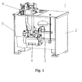
- FIG. 1 of the attached drawings shows a hydraulic power unit, indicated generally by reference number 1, comprising a pump 3, a motor 4, a tank 5, and a valve block 6, all inside a housing 2.
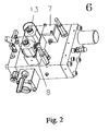
- valve block 6 is illustrated in greater detail in Figure 2, which shows a control valve 7 to control a starter valve (not shown), and a solenoid 8 to control a non-return valve (not shown) which are both constructed according to the teaching the invention.
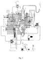
- FIG. 3 shows a schematic diagram of power unit 1 of the invention, with valve block 6 shown in cross section.
- this figure shows the passage of the oil from the motor 4-pump 3 unit to a piston 9, via the valve block 6.
- the various phases of movement of the elevator are controlled primarily by a starter or bypass valve 10, a deceleration valve 11, and a non-return or check valve 12.
- the starter valve 10 and the check valve 12 are made in accordance with the invention. It has been found in operation that the noise generated in the up run of the elevator comes mainly from the starter valve 10 and in the descent from the non-return valve 12.
- Power is supplied to the motor 4, sending oil from the tank 5 to the valve block 6.
- a valve 15 opens, and the valve 10 opens since the oil containing chamber 17 thereof discharges into the tank 5 through the open control valve 7, and the oil recirculates from the pump 3 to the tank 5.
- Solenoid 13 is then energized, creating low pressure that allows a valve 18 to open; the oil contained in chamber 19 of the valve 18 is discharged into the tank 5 via the solenoid 13.
- the oil from the pump 3 passes through a passage 21 and closes the valve 7; the oil passes through an adjustable throttle 20 and reaches the chamber 17 of the valve 10. Then the valve 10 begins to close and pressurizes the valve unit 6. In this condition, the oil continues to partially circulate to the tank through the valve 7, and more particularly circulates through slots 32 in the valve body.
- valve 12 opens, the pressure of the oil overcoming the spring force of the valve and the pressure of the equipment. The oil then reaches the piston 9 and the system starts to accelerate.
- the adjustment screws on the throttle 20 may be loosened.
- valve body 12 has a plurality of relatively small holes 33 and a number (6) of larger holes 34 at one end. These holes allow the passage of the full hydraulic flow without pressure drop.
- the valve body 12 may, however be constructed without these larger holes 34 in certain cases.
- the screw 25 may be loosened.
- valve 18 rests against the end of its stroke, but oil continues to circulate through the channels 50 provided in the latter; the valve 10 is partially open so that some of the oil from the pump 3 is discharged into tank 5 via the slots 32. The system proceeds to leveling speed.
- valve 12 When stopping at the floor while ascending, the motor 4 is not powered, the solenoid 13 is not energized, the solenoid 8 is not energized, and the control valve 7 is open. Due to inertia the elevator cabin continues to move upward for a few tenths of a second. Then, due to pressure on piston 9, valve 12 closes and the cabin is stopped at the floor.
- solenoid 13 is energized, the solenoid 8 is energized, the control valve 7 is open. Since solenoid 8 is energized, it allows the oil under pressure to move the release piston 11, thereby opening the valve 12. Solenoid 13 is energized and allows the slide valve 18 to open. Power is not supplied to control valve 7 so allowing the slide valve 10 to open, increasing the flow downward and causing the cabin to accelerate.
- a choke 26 arranged in the passage leading from the release piston 11 may be replaced with one that has a larger diameter, an adjustment that is recommended only in the event of irregular operation.
- the motor 4 is not powered, the solenoid 13 is energized, the solenoid 8 is energized, and the control valve 7 is open.
- the valve 18 and valve 10 are completely open, the valve 12 is open so as to maintain constant pressure in chamber 27; for this purpose, a solenoid 28 is provided to release any excess pressure.
- the motor 4 is not powered, the solenoid 13 is not energized, the solenoid 8 is energized, and the control valve 7 is open. Since the solenoid 13 is de-energized, it causes the valve 18 and the valve 10 to shift to their closed positions, and the system begins to slow down.
- screw 25 To increase deceleration while descending (and also ascending), screw 25 must be loosened.
- valve 18 rests against the end of its stroke, but oil continues to circulate through the channels provided in the latter.
- the closing of valve 18 causes a drop in pressure, which causes the valve 10 also to close. Oil is then discharged into the tank more slowly and the system proceeds to leveling speed.
- the throttle 26 may be replaced by one that has a smaller diameter.
- valves 10 and 12 are made in such a way as to force the fluid to pass through fine holes in a wall of the valve body during certain phases of operation of the system, in particular when the valves are opening, closing or in a partially open or closed state.
- the holes are in the form of rectangular slots 32, while in Figure 5 holes 33 are circular.
- the valves are generally cup shaped with the holes passing through the side walls thereof. In the case of a 30 - 40 mm diameter valve body, the wall thickness might typically be 2.5mm.
- bypass valve 10 is provided with slots 32 while the check valve is provided with circular holes 33.
- the valve body 12 is provided with larger diameter holes 34 adjacent its end to allow flow of fluid therethrough in its fully open state without significant pressure losses.
- the particular form of the passageways is not limited to those shown, nor is their number.
- the advantage of passing flow through relatively small holes 32 or 33 is that the fluid at valve 15 has a lower Reynolds number ⁇ and, therefore, along with a cavitation number ⁇ , the probability of the onset of cavitation itself is reduced, with a resulting drop in noise.
- valve 10, 12 will vary, however, in regard to the number and form of the holes, with the function of the flow rate of the pump 3. Typical values for rectangular holes and circular holes in bypass and check spool valves 10,12 are given in Tables 1 and 2 below.
- Pump Flow Rate (l min -1 ) Number of Slots (20 mm long) Slot Width (mm) 50-75 4 2 76-121 4 2 122-146 4 3 147-191 4 4 192-247 4 4 - 40 mm diameter by pass spool valve
- Pump Flow Rate (l min -1 ) Number of Holes Hole diameter (mm) 50-75 70 1.2 76-121 70 1.2 122-146 58 1.5 147-191 58 1.5 192-247 58 1.7 40 mm diameter check valve spool The above values are determined by specific studies and verified empirically to give optimum noise reduction while not compromising the hydraulic performance of the apparatus but bearing in mind the technical flexibility of the hole sizes. For example at high flow rates too small a hole diameter, whilst being quiet, may lead
- valves 10, 12 are made with thin walls, so as to reduce temperature-dependent variations in the viscosity of the oil.
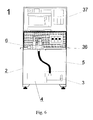
- the power unit 1 is shown with a soundproof compartment 36 in which is housed valve unit 6, said compartment 36 being covered with padded sheets of sound-absorbing or sound-insulating material, so as to further reduce the noise of the hydraulic power unit.
- the compartment 36 may be provided with an inspection panel to allow access to the valve unit 6.
- compartment 36 Resting on top of compartment 36 is electric panel 37, which in known hydraulic power units is placed elsewhere in the machine.
Landscapes
- Engineering & Computer Science (AREA)
- General Engineering & Computer Science (AREA)
- Mechanical Engineering (AREA)
- Chemical & Material Sciences (AREA)
- Analytical Chemistry (AREA)
- Physics & Mathematics (AREA)
- Fluid Mechanics (AREA)
- Types And Forms Of Lifts (AREA)
- Details Of Valves (AREA)
- Fluid-Pressure Circuits (AREA)
- Lift Valve (AREA)
- Multiple-Way Valves (AREA)
Applications Claiming Priority (2)
| Application Number | Priority Date | Filing Date | Title |
|---|---|---|---|
| ITRM980377 | 1998-06-10 | ||
| IT98RM000377A IT1299508B1 (it) | 1998-06-10 | 1998-06-10 | Valvola perfezionata per centralina idraulica, in particolare per ascensori, montacarichi e simili |
Publications (3)
| Publication Number | Publication Date |
|---|---|
| EP0964163A2 true EP0964163A2 (fr) | 1999-12-15 |
| EP0964163A3 EP0964163A3 (fr) | 2001-11-28 |
| EP0964163B1 EP0964163B1 (fr) | 2005-11-16 |
Family
ID=11405971
Family Applications (1)
| Application Number | Title | Priority Date | Filing Date |
|---|---|---|---|
| EP99304562A Expired - Lifetime EP0964163B1 (fr) | 1998-06-10 | 1999-06-10 | Soupape pour une centrale hydraulique |
Country Status (4)
| Country | Link |
|---|---|
| EP (1) | EP0964163B1 (fr) |
| DE (1) | DE69928326T2 (fr) |
| ES (1) | ES2248968T3 (fr) |
| IT (1) | IT1299508B1 (fr) |
Cited By (2)
| Publication number | Priority date | Publication date | Assignee | Title |
|---|---|---|---|---|
| WO2002002974A2 (fr) | 2000-07-03 | 2002-01-10 | Wittur Ag | Unite soupape de commande pour un ascenseur hydraulique |
| WO2023169779A1 (fr) * | 2022-03-10 | 2023-09-14 | Zf Friedrichshafen Ag | Vanne de réduction de pression |
Family Cites Families (7)
| Publication number | Priority date | Publication date | Assignee | Title |
|---|---|---|---|---|
| US3813079A (en) * | 1971-12-10 | 1974-05-28 | Masoneilan Int Inc | Quick change apparatus for effecting gas flow pressure reduction with low noise generator |
| US3908698A (en) * | 1974-03-07 | 1975-09-30 | Hans D Baumann | Variable resistance type throttling trim |
| DE2431322C3 (de) * | 1974-06-29 | 1978-10-26 | Honeywell Gmbh, 6000 Frankfurt | Regelventil |
| DE8311997U1 (de) * | 1983-04-22 | 1984-09-27 | Blain, Roy William, 7100 Heilbronn | Senkventil zur Steuerung der Abwärtsgeschwindigkeit eines hydraulisch betriebenen Aufzuges |
| US4617963A (en) * | 1983-06-23 | 1986-10-21 | Mcgraw-Edison Company | Control valve with anticavitation trim |
| US4844701A (en) * | 1987-12-02 | 1989-07-04 | The Gorman-Rupp Company | Mobile pump apparatus |
| JPH07301201A (ja) * | 1994-04-28 | 1995-11-14 | Toyooki Kogyo Co Ltd | 油圧ユニツト |
-
1998
- 1998-06-10 IT IT98RM000377A patent/IT1299508B1/it active IP Right Grant
-
1999
- 1999-06-10 DE DE69928326T patent/DE69928326T2/de not_active Expired - Lifetime
- 1999-06-10 ES ES99304562T patent/ES2248968T3/es not_active Expired - Lifetime
- 1999-06-10 EP EP99304562A patent/EP0964163B1/fr not_active Expired - Lifetime
Non-Patent Citations (1)
| Title |
|---|
| None |
Cited By (4)
| Publication number | Priority date | Publication date | Assignee | Title |
|---|---|---|---|---|
| WO2002002974A2 (fr) | 2000-07-03 | 2002-01-10 | Wittur Ag | Unite soupape de commande pour un ascenseur hydraulique |
| WO2002002974A3 (fr) * | 2000-07-03 | 2002-05-23 | Wittur Ag | Unite soupape de commande pour un ascenseur hydraulique |
| US6742629B2 (en) | 2000-07-03 | 2004-06-01 | Wittur Ag | Valve control unit for a hydraulic elevator |
| WO2023169779A1 (fr) * | 2022-03-10 | 2023-09-14 | Zf Friedrichshafen Ag | Vanne de réduction de pression |
Also Published As
| Publication number | Publication date |
|---|---|
| ITRM980377A0 (it) | 1998-06-10 |
| IT1299508B1 (it) | 2000-03-16 |
| DE69928326T2 (de) | 2006-07-13 |
| EP0964163A3 (fr) | 2001-11-28 |
| ITRM980377A1 (it) | 1999-12-10 |
| EP0964163B1 (fr) | 2005-11-16 |
| ES2248968T3 (es) | 2006-03-16 |
| DE69928326D1 (de) | 2005-12-22 |
Similar Documents
| Publication | Publication Date | Title |
|---|---|---|
| EP0924159A2 (fr) | Générateur de pression hydraulique à faible bruit pour pont de voiture | |
| EP0964163B1 (fr) | Soupape pour une centrale hydraulique | |
| JP3447994B2 (ja) | 油圧エレベータ装置 | |
| US5988989A (en) | Compact hydraulic power unit having a reservoir closed by a manifold having a hydraulic circuit | |
| KR100313262B1 (ko) | 환기장치 | |
| WO2010106025A1 (fr) | Ascenseur à poulie motrice, dispositif d'entraînement pour un tel ascenseur à poulie motrice, et procédé d'exploitation d'un tel entraînement d'ascenseur | |
| DE102015215090B4 (de) | Versorgungsverfahren und Versorgungsvorrichtung zum Versorgen eines Hochdruckraumes einer Kraftstoffhochdruckpumpe für eine Brennkraftmaschine mit Kraftstoff | |
| US6044933A (en) | Hydraulic elevator | |
| JPH0624665A (ja) | エレベータ利用のビル換気装置 | |
| WO2001085593A1 (fr) | Frein d'arret d'ascenseur | |
| US4412600A (en) | Hydraulic elevator | |
| US3001367A (en) | Hydraulic elevator control system | |
| EP0213216A1 (fr) | Machine soufflante à piston rotatif | |
| US3606243A (en) | Device for preventing noise in an oil-hydraulic elevator | |
| JP4419914B2 (ja) | オイル排出装置 | |
| WO2007143871A2 (fr) | Installation d'ascenseur | |
| JP2003002560A (ja) | 水圧エレベータ | |
| US6059073A (en) | Overspeed valve for hydraulic elevator | |
| DE1053710B (de) | Anordnung zur Hubbegrenzung eines elektromagnetischen Schwingkompressors | |
| JP2672669B2 (ja) | 油圧エレベータ用パワーユニット | |
| JP2515690B2 (ja) | 磁気を利用したエレベ―タ装置 | |
| JP3395528B2 (ja) | 油圧エレベータ装置 | |
| JPS61226328A (ja) | パワ−ユニツトのマウンテイング装置 | |
| JP4019633B2 (ja) | 油圧エレベータ | |
| JPH101266A (ja) | 油圧エレベータの制御装置 |
Legal Events
| Date | Code | Title | Description |
|---|---|---|---|
| PUAI | Public reference made under article 153(3) epc to a published international application that has entered the european phase |
Free format text: ORIGINAL CODE: 0009012 |
|
| AK | Designated contracting states |
Kind code of ref document: A2 Designated state(s): AT BE CH CY DE DK ES FI FR GB GR IE IT LI LU MC NL PT SE Kind code of ref document: A2 Designated state(s): DE ES FR GB IT |
|
| AX | Request for extension of the european patent |
Free format text: AL;LT;LV;MK;RO;SI |
|
| PUAL | Search report despatched |
Free format text: ORIGINAL CODE: 0009013 |
|
| AK | Designated contracting states |
Kind code of ref document: A3 Designated state(s): AT BE CH CY DE DK ES FI FR GB GR IE IT LI LU MC NL PT SE |
|
| AX | Request for extension of the european patent |
Free format text: AL;LT;LV;MK;RO;SI |
|
| 17P | Request for examination filed |
Effective date: 20020506 |
|
| AKX | Designation fees paid |
Free format text: DE ES FR GB |
|
| RBV | Designated contracting states (corrected) |
Designated state(s): DE ES FR GB IT |
|
| 17Q | First examination report despatched |
Effective date: 20031126 |
|
| GRAP | Despatch of communication of intention to grant a patent |
Free format text: ORIGINAL CODE: EPIDOSNIGR1 |
|
| GRAS | Grant fee paid |
Free format text: ORIGINAL CODE: EPIDOSNIGR3 |
|
| GRAA | (expected) grant |
Free format text: ORIGINAL CODE: 0009210 |
|
| AK | Designated contracting states |
Kind code of ref document: B1 Designated state(s): DE ES FR GB IT |
|
| REG | Reference to a national code |
Ref country code: GB Ref legal event code: FG4D |
|
| REF | Corresponds to: |
Ref document number: 69928326 Country of ref document: DE Date of ref document: 20051222 Kind code of ref document: P |
|
| REG | Reference to a national code |
Ref country code: ES Ref legal event code: FG2A Ref document number: 2248968 Country of ref document: ES Kind code of ref document: T3 |
|
| PGFP | Annual fee paid to national office [announced via postgrant information from national office to epo] |
Ref country code: ES Payment date: 20060602 Year of fee payment: 8 |
|
| PGFP | Annual fee paid to national office [announced via postgrant information from national office to epo] |
Ref country code: IT Payment date: 20060630 Year of fee payment: 8 |
|
| ET | Fr: translation filed | ||
| PLBE | No opposition filed within time limit |
Free format text: ORIGINAL CODE: 0009261 |
|
| STAA | Information on the status of an ep patent application or granted ep patent |
Free format text: STATUS: NO OPPOSITION FILED WITHIN TIME LIMIT |
|
| 26N | No opposition filed |
Effective date: 20060817 |
|
| REG | Reference to a national code |
Ref country code: ES Ref legal event code: FD2A Effective date: 20070611 |
|
| PG25 | Lapsed in a contracting state [announced via postgrant information from national office to epo] |
Ref country code: ES Free format text: LAPSE BECAUSE OF NON-PAYMENT OF DUE FEES Effective date: 20070611 |
|
| PG25 | Lapsed in a contracting state [announced via postgrant information from national office to epo] |
Ref country code: IT Free format text: LAPSE BECAUSE OF NON-PAYMENT OF DUE FEES Effective date: 20070610 |
|
| PGFP | Annual fee paid to national office [announced via postgrant information from national office to epo] |
Ref country code: FR Payment date: 20110621 Year of fee payment: 13 |
|
| PGFP | Annual fee paid to national office [announced via postgrant information from national office to epo] |
Ref country code: GB Payment date: 20110608 Year of fee payment: 13 |
|
| PGFP | Annual fee paid to national office [announced via postgrant information from national office to epo] |
Ref country code: DE Payment date: 20110608 Year of fee payment: 13 |
|
| GBPC | Gb: european patent ceased through non-payment of renewal fee |
Effective date: 20120610 |
|
| REG | Reference to a national code |
Ref country code: FR Ref legal event code: ST Effective date: 20130228 |
|
| REG | Reference to a national code |
Ref country code: DE Ref legal event code: R119 Ref document number: 69928326 Country of ref document: DE Effective date: 20130101 |
|
| PG25 | Lapsed in a contracting state [announced via postgrant information from national office to epo] |
Ref country code: GB Free format text: LAPSE BECAUSE OF NON-PAYMENT OF DUE FEES Effective date: 20120610 Ref country code: FR Free format text: LAPSE BECAUSE OF NON-PAYMENT OF DUE FEES Effective date: 20120702 Ref country code: DE Free format text: LAPSE BECAUSE OF NON-PAYMENT OF DUE FEES Effective date: 20130101 |