EP0964194A2 - Überdruckventil - Google Patents
Überdruckventil Download PDFInfo
- Publication number
- EP0964194A2 EP0964194A2 EP99304543A EP99304543A EP0964194A2 EP 0964194 A2 EP0964194 A2 EP 0964194A2 EP 99304543 A EP99304543 A EP 99304543A EP 99304543 A EP99304543 A EP 99304543A EP 0964194 A2 EP0964194 A2 EP 0964194A2
- Authority
- EP
- European Patent Office
- Prior art keywords
- liquid chamber
- sliding portion
- piston
- face
- relief valve
- Prior art date
- Legal status (The legal status is an assumption and is not a legal conclusion. Google has not performed a legal analysis and makes no representation as to the accuracy of the status listed.)
- Granted
Links
Images


Classifications
-
- F—MECHANICAL ENGINEERING; LIGHTING; HEATING; WEAPONS; BLASTING
- F16—ENGINEERING ELEMENTS AND UNITS; GENERAL MEASURES FOR PRODUCING AND MAINTAINING EFFECTIVE FUNCTIONING OF MACHINES OR INSTALLATIONS; THERMAL INSULATION IN GENERAL
- F16K—VALVES; TAPS; COCKS; ACTUATING-FLOATS; DEVICES FOR VENTING OR AERATING
- F16K17/00—Safety valves; Equalising valves, e.g. pressure relief valves
- F16K17/02—Safety valves; Equalising valves, e.g. pressure relief valves opening on surplus pressure on one side; closing on insufficient pressure on one side
- F16K17/04—Safety valves; Equalising valves, e.g. pressure relief valves opening on surplus pressure on one side; closing on insufficient pressure on one side spring-loaded
- F16K17/08—Safety valves; Equalising valves, e.g. pressure relief valves opening on surplus pressure on one side; closing on insufficient pressure on one side spring-loaded with special arrangements for providing a large discharge passage
- F16K17/082—Safety valves; Equalising valves, e.g. pressure relief valves opening on surplus pressure on one side; closing on insufficient pressure on one side spring-loaded with special arrangements for providing a large discharge passage with piston
-
- F—MECHANICAL ENGINEERING; LIGHTING; HEATING; WEAPONS; BLASTING
- F16—ENGINEERING ELEMENTS AND UNITS; GENERAL MEASURES FOR PRODUCING AND MAINTAINING EFFECTIVE FUNCTIONING OF MACHINES OR INSTALLATIONS; THERMAL INSULATION IN GENERAL
- F16K—VALVES; TAPS; COCKS; ACTUATING-FLOATS; DEVICES FOR VENTING OR AERATING
- F16K17/00—Safety valves; Equalising valves, e.g. pressure relief valves
- F16K17/02—Safety valves; Equalising valves, e.g. pressure relief valves opening on surplus pressure on one side; closing on insufficient pressure on one side
- F16K17/04—Safety valves; Equalising valves, e.g. pressure relief valves opening on surplus pressure on one side; closing on insufficient pressure on one side spring-loaded
- F16K17/06—Safety valves; Equalising valves, e.g. pressure relief valves opening on surplus pressure on one side; closing on insufficient pressure on one side spring-loaded with special arrangements for adjusting the opening pressure
- F16K17/065—Safety valves; Equalising valves, e.g. pressure relief valves opening on surplus pressure on one side; closing on insufficient pressure on one side spring-loaded with special arrangements for adjusting the opening pressure with differential piston
-
- F—MECHANICAL ENGINEERING; LIGHTING; HEATING; WEAPONS; BLASTING
- F16—ENGINEERING ELEMENTS AND UNITS; GENERAL MEASURES FOR PRODUCING AND MAINTAINING EFFECTIVE FUNCTIONING OF MACHINES OR INSTALLATIONS; THERMAL INSULATION IN GENERAL
- F16K—VALVES; TAPS; COCKS; ACTUATING-FLOATS; DEVICES FOR VENTING OR AERATING
- F16K47/00—Means in valves for absorbing fluid energy
- F16K47/01—Damping of valve members
- F16K47/011—Damping of valve members by means of a dashpot
- F16K47/0111—Damping of valve members by means of a dashpot the valve members comprising a plunger sliding within a fixed dashpot
-
- Y—GENERAL TAGGING OF NEW TECHNOLOGICAL DEVELOPMENTS; GENERAL TAGGING OF CROSS-SECTIONAL TECHNOLOGIES SPANNING OVER SEVERAL SECTIONS OF THE IPC; TECHNICAL SUBJECTS COVERED BY FORMER USPC CROSS-REFERENCE ART COLLECTIONS [XRACs] AND DIGESTS
- Y10—TECHNICAL SUBJECTS COVERED BY FORMER USPC
- Y10T—TECHNICAL SUBJECTS COVERED BY FORMER US CLASSIFICATION
- Y10T137/00—Fluid handling
- Y10T137/7722—Line condition change responsive valves
- Y10T137/7837—Direct response valves [i.e., check valve type]
- Y10T137/785—With retarder or dashpot
- Y10T137/7852—End of valve moves inside dashpot chamber
Definitions
- the invention relates to a relief valve to be used for controlling a hydraulic pressure of a hydraulic circuit.
- a hydraulic motor is generally used for a turning motor and a traveling motor for a construction machine vehicle, and is driven by a hydraulic circuit.
- a relief valve is used for controlling a hydraulic pressure of the hydraulic circuit.
- Fig. 8 shows an example of a hydraulic circuit using a relief valve.
- a relief valve R10 communicates to a pressurized liquid supply port and a pressurized liquid exhaust port of a hydraulic motor M, respectively.
- An escape side of the relief valve R10 communicates to a liquid tank T through a boost check valve B for keeping a suction pressure of the motor.
- P denotes a hydraulic pump and V denotes a switching valve.
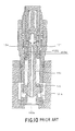
- Fig. 10 is a sectional view showing a relief valve disclosed in Japanese Utility Model Publication No. Hei 7-23663.
- a plunger 103 is pressed forward by means of a coiled spring 105.
- the plunger 103 moves rearward against elastic force of the coiled spring 105 to make an inlet 102a and an outlet 101a communicate with each other when a pressure of the inlet 102a is raised.
- a rear end of the coiled spring 105 is pushed forward by means of a piston 104 inserted and fitted in an inner bore of a case 101 for sliding.
- the piston 104 moves forward to compress the coiled spring 105 when the pressure of the inlet 102a is raised.
- a relief pressure is regulated.
- the plunger 103 can slide along a central axis of the piston 104.
- an annular sectional area having a diameter d104 as an outside diameter and a diameter d103 as an inside diameter is an effective pressure receiving area for actuating the piston 104.
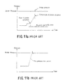
- the annular sectional area is excessively large, the piston 104 is actuated at a low pressure. Consequently, the actuation of the piston 104 is completed before the pressure of the inlet 102a reaches the relief pressure. As a result, a surge pressure is generated before the pressure of the inlet 102a reaches the relief pressure.
- Fig. 11A shows a temporal change of a pressure in the inlet 102a.
- the invention provides a relief valve in which a plunger pressed forward by a spring to shut off between an inlet and an outlet moves rearward against elastic force of the spring with an increase in a pressure of the inlet, thereby making the inlet and the outlet communicate with each other, and a piston for pushing forward a rear end of the spring moves forward with the increase in the pressure of the inlet to compress the spring, thereby regulating a relief pressure.
- the piston has a first sliding portion for sliding with liquidtightness in an inner bore of a case, a rear portion of the plunger is slidably inserted and fitted in a sliding bore formed along a central axis of the piston, the plunger has a through hole for feeding a pressurized liquid from the inlet to the back of the plunger, a third liquid chamber is realized by a space of a rear portion of the sliding bore that the plunger does not reach and the through hole,
- the relief valve may be constructed in such a manner that an area of the forward acting face is greater than an total area of an area of the bottom face of the sliding bore and an area of the rearward acting face, and the difference between the rearward acting force and the forward acting force is generated by a difference between the area of the forward acting face and the total area.
- the relief valve may be constructed in such a manner that a second sliding portion having a diameter larger than a diameter of the first sliding portion and a third sliding portion having a diameter smaller than the diameter of the first sliding portion are provided to be positioned rearward than the first sliding portion on the piston respectively, the second sliding portion slides with liquidtightness in the inner bore of the case, the third sliding portion slides with liquidtightness in an inner bore formed on a cap fixed to the case, the rearward acting face is provided on a front end face of the second sliding portion and the forward acting face is provided on a rear end face of the second sliding portion, and a liquid chamber on which a rear end face of the third sliding portion fronts communicates with the outlet.
- the relief valve may be constructed in such a manner that a second sliding portion having a diameter larger than a diameter of the first sliding portion and a third sliding portion having a diameter smaller than the diameter of the first sliding portion are provided to be positioned rearward than the first sliding portion on the piston respectively, the second sliding portion slides with liquidtightness in the inner bore of the case, the third sliding portion slides with liquidtightness in an inner bore formed on a cap fixed to the case, the rearward acting face is provided on a front end face of the second sliding portion and the forward acting face is provided on a rear end face of the third sliding portion, and a liquid chamber on which a rear end face of the second sliding portion fronts communicates with the outlet.
- the difference between the area of the bottom face of the sliding bore and the rearward acting face and that of the forward acting face is set to the effective pressure receiving area of the piston. Consequently, the effective pressure receiving area is set irrespective of the thickness of the first sliding portion of the piston. Therefore, the effective pressure receiving area can be reduced without generating the insufficient strength of the piston. Accordingly, the piston can perform stroke until the pressure of the inlet reaches the relief pressure, thereby a surge pressure can be prevented from being generated.
- the relief valve may be constructed in such a manner that the third liquid chamber and the first liquid chamber communicate with each other through a communicating hole having a restriction, and the third liquid chamber and the second liquid chamber communicate with each other through a communicating hole having no restriction.
- the relief valve may be constructed in such a manner that the third liquid chamber and the second liquid chamber communicate with each other through a communicating hole having no restriction, the first liquid chamber and the second liquid chamber communicate with each other through a communicating hole having a restriction, and the third liquid chamber and the first liquid chamber communicate with each other through the second liquid chamber.
- the relief valve may be constructed in such a manner that the third liquid chamber and the second liquid chamber communicate with each other through a communicating hole having a restriction, and the third liquid chamber and the first liquid chamber communicate with each other through a communicating hole having no restriction.
- the relief valve may be constructed in such a manner that the third liquid chamber and the first liquid chamber communicate with each other through a communicating hole having no restriction, the first liquid chamber and the second liquid chamber communicate with each other through a communicating hole having a restriction, and the third liquid chamber and the second liquid chamber communicate with each other through the first liquid chamber.
- the relief valve may be constructed in such a manner that a pressure difference is generated between front and rear of the restriction by a difference between the rearward acting force and the forward acting force, and the piston moves forward while the pressurized liquid passes through the restriction.
- the first liquid chamber has a pressure higher than the pressure of the second liquid chamber. If the effective pressure receiving area is reduced, the pressure difference between front and rear of the restriction is reduced. Consequently, an exhaust flow velocity is reduced when the piston moves forward, and the piston slowly moves forward. As a result, the pressure rise buffer time is increased. Alternatively, if the sectional area of the restriction is increased, the pressure rise buffer time is shortened. Thus, the pressure rise buffer time can be set freely.
- Fig. 1 is a longitudinal sectional view showing a relief valve R1 according to an embodiment of the invention.
- the relief valve R1 mainly comprises an substantially cylindrical case 1, a valve seat 2 fixed to a tip of the case 1, a plunger 3 provided in the case 1, a piston 4 provided in the case 1, a coiled spring 5 existing between the plunger 3 and the piston 4, and a cap 6 fixed to a rear end of the case 1.
- An inner bore of the case 1 has a front portion formed with an inside diameter d4 and a rear portion formed with an inside diameter d1.
- the inside diameter d1 is greater than the inside diameter d4.
- An outlet la and a passage 1b are formed on a side face of the case 1.
- the valve seat 2 is formed of an annular member and a central portion thereof functions as an inlet 2a for a pressurized liquid.
- a tip of the plunger 3 has a tapered and truncated conical shape.
- a through hole 3a is formed in the center of the plunger 3.
- the through hole 3a penetrates from the tip of the plunger 3 to a rear end thereof, thereby feeding the pressurized liquid from the inlet 2a toward a rear portion of the plunger 3, and has a restriction 3b formed in the middle thereof.
- the restriction 3b is provided for giving damping force to the actuation of the plunger 3 and for preventing hunting.
- a first sliding portion 4a having an outside diameter d4 is formed in a front portion of the piston 4.
- a second sliding portion 4b having an outside diameter dl which acts as a large diameter portion is formed on the piston 4 to be positioned behind the first sliding portion 4a.
- the first sliding portion 4a is slidably inserted and fitted with liquidtightness in an portion having inside diameter d4 of the inner bore of the case 1.
- the second sliding portion 4b is slidably inserted and fitted with liquidtightness in an portion having inside diameter dl of the inner bore of the case 1.
- the third sliding portion 4c has an outside diameter d2.
- the piston 4 has a sliding bore opened on a front face thereof along a central axis.
- the sliding bore has an inside diameter d3.
- the rear portion of the plunger 3 is slidably inserted and fitted in the sliding bore.
- a third liquid chamber 40 is realized by a rear space 4d of the sliding bore and a through hole 3a of the plunger 3.
- the rear space 4d of the sliding bore is formed in such a manner that the rear end of the plunger 3 does not reach thereto even if the plunger 3 slides to a rearmost portion of a slidable range.
- the state that the plunger 3 slides to a rearmost portion of a slidable range means a state that the coiled spring 5 is compressed completely.
- the piston 4 has a passage 4e formed thereon.
- the passage 4e penetrates from a front end face of the first sliding portion 4a toward a rear end face of the third sliding portion 4c.
- a communicating hole 11 and a communicating hole 12 are formed in the piston 4.
- a restriction 11a is formed in a part of the communicating hole 11.
- a restriction is not formed in the communicating hole 12.
- a front end face of the large diameter portion (second sliding portion) 4b functions as a rearward acting face 21 on which a pressurized liquid acts.
- a first liquid chamber 22 on which the rearward acting face 21 fronts communicates with the third liquid chamber 40 through the communicating hole 11.
- a rear end face of the large diameter portion (second sliding portion) 4b functions as a forward acting face 31 on which the pressurized liquid acts.
- a second liquid chamber 32 on which the forward acting face 31 fronts communicates
- the coiled spring 5 is accommodated in a spring chamber 8 (fifth liquid chamber) formed between an inner peripheral face of the case 1 and an outer peripheral face of the plunger 3.
- the coiled spring 5 is provided to contract in such a manner that a tip presses a bulky portion 3c of the plunger 3 forward from the back and a rear end presses the front end face of the first sliding portion 4a of the piston 4 rearward through a spring seat 7.
- the cap 6 is screwed to close an opening on a rear side of the inner hole of the case 1.
- a bore 6a opened forward is formed on the cap 6 along a central axis.
- the bore 6a and the rear end portion of the piston 4 form a fourth liquid chamber.
- the bore 6a has an inside diameter d2, and the third sliding portion 4c of the piston 4 is inserted and fitted to be slidable in the bore 6a.
- the fourth liquid chamber communicates with the spring chamber 8 (fifth liquid chamber) through the passage 4e. Thereby, the fourth liquid chamber communicates with the outlet la through the spring chamber 8 (fifth liquid chamber) and passage 1b.
- the relief valve R1 has a structure summarized above, and acts in the following manner with a rise in a hydraulic pressure of the inlet 2a. More specifically, before the hydraulic pressure of the inlet 2a is raised, the tip of the plunger 3 covers the inlet 2a, thereby the inlet 2a is shut off with the outlet la. When the hydraulic pressure of the inlet 2a is started to be raised, the plunger 3 starts rearward movement by the hydraulic pressure against the elastic force of the coiled spring 5, thereby the inlet 2a and the outlet la communicate with each other.
- the pressurized liquid in the inlet 2a is fed to the third liquid chamber 40 through the through hole 3a, then acts on bottom faces 23 and 24 of the sliding bores.
- the pressurized liquid in the third liquid chamber 40 is fed to the first liquid chamber 22 and the second liquid chamber 32 through the communicating holes 11 and 12, then acts on the rearward acting face 21 and the forward acting face 31.
- the area of the forward acting face 31 is greater than a total area of an area of bottom faces 23,24 and that of the rearward acting face 21. Therefore, by the operation of the pressurized liquid flowing into the third liquid chamber 40 through the communicating hole 11 and the restriction 11a, the piston 4 starts forward movement while pushing the rear end of the coiled spring 5 forward.
- the coiled spring 5 is compressed by the movement of both of the plunger 3 and the piston 4. Thereby, a rapid rise in a pressure of the inlet 2a is relieved and subjected to relief to the outlet 1a. Thus, a relief pressure is regulated.
- the spring chamber 8 (fifth liquid chamber) communicates with a liquid tank T through a boost check valve for keeping a suction pressure.
- the spring chamber 8 has a hydraulic pressure which almost approximates to a tank pressure.
- the bore 6a of the cap 6 communicates with the tank T through the passage 4e, the spring chamber 8 and the boost check valve, and a hydraulic pressure thereof also has a value which almost approximates to the value of a tank pressure. Accordingly, the effective pressure receiving area of the piston 4 is obtained by subtracting a total of the areas of the bottom faces 23 and 24 and the rearward acting face 21 from the area of the forward acting face 31.
- an effective pressure receiving area A1 of the piston is expressed by the following equation (a pressure of the spring chamber 8 approximates to 0 in the following equation).
- A1 (d4 2 -d3 2 -d2 2 ) ⁇ ( ⁇ /4)
- the effective pressure receiving area A1 can be set freely by setting the values of d2, d3 and d4.
- the value of A1 can be reduced by an increase in the value of d2. More specifically, the effective pressure receiving area A1 of the piston can be reduced to approximate to the effective pressure receiving area of the plunger 3 of ( ⁇ /4) ⁇ (d5 2 - d3 2 ) without reducing the thickness of the first sliding portion 4a.
- d5 represents a diameter of a portion of the valve seat 2 on which the plunger 3 is placed. Accordingly, it is possible to avoid a situation that the piston 4 completes actuation before the pressure of the inlet 2a reaches the relief pressure while fully keeping the strength of the piston 4. Consequently, it is also possible to prevent a surge pressure from being generated.
- the effective pressure receiving area A1 can be reduced. Therefore, a pressure rise buffer time, that continues after the actuation of the plunger 3 is started until the relief pressure is reached, can also be set long. More specifically, if the effective pressure receiving area Al is small, the force for actuating the piston 4 is reduced. Consequently, the pressure of the first liquid chamber 22 is slightly raised with the movement of the piston 4. In other words, a pressure difference ⁇ p is reduced between front and rear of the restriction 11a.
- the first liquid chamber 22 has a pressure higher than the pressure of the second liquid chamber 32.
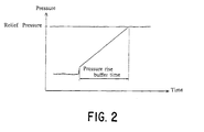
- Fig. 2 is a chart showing a temporal change of a pressure in the inlet 2a of the relief valve.
- the chart shows a state in which the surge pressure is not generated because the pressure rise buffer time is set long and the actuation of the piston 4 is not completed before the pressure of the inlet 2a reaches the relief pressure.
- the pressure rise buffer time can be set freely.
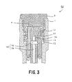
- Fig. 3 is a longitudinal sectional view showing the periphery of a piston 4 of a relief valve R2 according to another embodiment of the invention.
- the relief valve R2 is constructed in such a manner that the piston 4 is not provided with a communicating hole for directly coupling a third liquid chamber 40 and a first liquid chamber 22 together but is provided with a communicating hole 13 for causing the first liquid chamber 22 and a second liquid chamber 32 to communicate with each other.
- the relief valve R2 is different from the relief valve R1 shown in Fig. 1.
- the first liquid chamber 22 indirectly communicates with the third liquid chamber 40 through a communicating hole 12 and the communicating hole 13.
- a restriction is not formed in the communicating hole 12 but a restriction 13a is formed in the communicating hole 13.
- the first liquid chamber 22 has a pressure higher than the pressure of the second liquid chamber 32 and serves to regulate a pressure rise buffer time.
- Other structures are the same as in the relief valve R1 shown in Fig. 1.
- the action of the relief valve R2 is the same as that of the relief valve R1 shown in Fig. 1.
- Fig. 4 is a longitudinal sectional view showing the periphery of a piston 4 of a relief valve R3 according to yet another embodiment of the invention.
- the relief valve R3 is constructed in such a manner that a restriction is not formed in a communicating hole 14 for causing a third liquid chamber 40 and a first liquid chamber 22 to communicate with each other but a restriction 15a is formed in a communicating hole 15 for causing the third liquid chamber 40 and a second liquid chamber 32 to communicate with each other.
- the relief valve R3 is different from the relief valve R1 shown in Fig. 1.
- the first liquid chamber 22 has a pressure higher than the pressures of the second liquid chamber 32 and the third liquid chamber 40.
- Fig. 5 is a longitudinal sectional view showing the periphery of a piston 4 of a relief valve R4 according to a further embodiment of the invention.
- the relief valve R4 is constructed in such a manner that the piston 4 is not provided with a communicating hole for directly coupling a third liquid chamber 40 and a second liquid chamber 32 together but is provided with a communicating hole 13 for causing a first liquid chamber 22 and the second liquid chamber 32 to communicate with each other.
- the relief valve R4 is different from the relief valve R3 shown in Fig. 4.
- the second liquid chamber 32 indirectly communicates with the third liquid chamber 40 through a communicating hole 14 and the communicating hole 13.
- a restriction is not formed in the communicating hole 14 but a restriction 13a is formed in the communicating hole 13.
- the first liquid chamber 22 has a pressure higher than the pressure of the second liquid chamber 32 and serves to regulate a pressure rise buffer time.
- the action of the relief valve R4 is also the same as that of the relief valve R1 shown in Fig. 1.
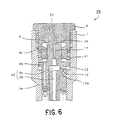
- Fig. 6 is a longitudinal sectional view showing the periphery of a piston 4 of a relief valve R5 according to a further embodiment of the invention.
- the relief valve R5 is constructed in such a manner that a rear end face of a second sliding portion 4b acting as a large diameter portion does not function as a forward acting face 33 but a rear end face of a third sliding portion 4c functions as the forward acting face 33.
- the relief valve R5 is different from the relief valve R1 shown in Fig. 1.
- a bore formed on a cap 6 acts as a second liquid chamber 34 and has a high pressure to function as a liquid chamber for generating a forward acting pressure.
- the piston 4 is provided with a communicating hole 16 for causing a sliding bore and a first liquid chamber 22 to communicate with each other and a communicating hole 17 for causing the sliding bore and the second liquid chamber 34 to communicate with each other.
- a restriction 16a is formed in the communicating hole 16.
- a pressure of the first liquid chamber 22 is higher than that of a liquid chamber 41 on which the rear end face of the second sliding portion 4b fronts, and controls an outflow time of a liquid.
- the pressure of the liquid chamber 41 is caused to communicate with a tank pressure through a passage 4e formed in the piston 4 by means of a boost check valve or the like for keeping a suction pressure.
- the action of the relief valve R5 is also the same as that of the relief valve R1 shown in Fig. 1.
- Fig. 7 is a longitudinal sectional view showing the periphery of a piston 4 of a relief valve R6 according to a further embodiment of the invention.
- the relief valve R6 is different from the relief valve R5 shown in Fig. 6 in that a bottom face of a bore opened rearward on the piston 4 functions as a forward acting face 35.
- the bore acts as a second liquid chamber 36, and has a high pressure to function as a liquid chamber for generating a forward acting pressure.
- the piston 4 is provided with a communicating hole 16 for causing a third liquid chamber 40 and a first liquid chamber 22 to communicate with each other and a communicating hole 17 for causing the third liquid chamber 40 and the second liquid chamber 36 to communicate with each other.
- the first liquid chamber 22 functions as a high pressure chamber in which a pressure is higher than in the third liquid chamber 40.
- the action of the relief valve R6 is also the same as that of the relief valve R1 shown in Fig. 1.
- Numeral 4e denotes a passage for causing a hydraulic pressure of a liquid chamber 42 to communicate with a tank pressure through a boost check valve.
- a pressure of a spring chamber 8 (fifth liquid chamber) has a value which almost approximates to the value of the tank pressure.
Landscapes
- Engineering & Computer Science (AREA)
- General Engineering & Computer Science (AREA)
- Mechanical Engineering (AREA)
- Safety Valves (AREA)
Applications Claiming Priority (2)
| Application Number | Priority Date | Filing Date | Title |
|---|---|---|---|
| JP16481398 | 1998-06-12 | ||
| JP10164813A JP2908435B1 (ja) | 1998-06-12 | 1998-06-12 | リリーフ弁 |
Publications (3)
| Publication Number | Publication Date |
|---|---|
| EP0964194A2 true EP0964194A2 (de) | 1999-12-15 |
| EP0964194A3 EP0964194A3 (de) | 2001-04-11 |
| EP0964194B1 EP0964194B1 (de) | 2004-10-20 |
Family
ID=15800416
Family Applications (1)
| Application Number | Title | Priority Date | Filing Date |
|---|---|---|---|
| EP99304543A Expired - Lifetime EP0964194B1 (de) | 1998-06-12 | 1999-06-10 | Überdruckventil |
Country Status (5)
| Country | Link |
|---|---|
| US (1) | US6142176A (de) |
| EP (1) | EP0964194B1 (de) |
| JP (1) | JP2908435B1 (de) |
| KR (1) | KR100341962B1 (de) |
| DE (1) | DE69921233T2 (de) |
Cited By (5)
| Publication number | Priority date | Publication date | Assignee | Title |
|---|---|---|---|---|
| DE10063153A1 (de) * | 2000-12-18 | 2002-06-20 | Mannesmann Rexroth Ag | Direktgesteuertes Druckbegrenzungsventil |
| FR2899664A1 (fr) * | 2006-04-10 | 2007-10-12 | Eaton Sa Monegasque | Dispositif limiteur de pression |
| CN102444733A (zh) * | 2011-12-14 | 2012-05-09 | 四川省机械研究设计院 | 一种自缓冲多级安全阀 |
| EP1821014A4 (de) * | 2004-11-25 | 2012-08-15 | Kayaba Industry Co Ltd | Entlüftungsventil |
| CN112534168A (zh) * | 2019-04-20 | 2021-03-19 | 川崎重工业株式会社 | 泄压阀 |
Families Citing this family (21)
| Publication number | Priority date | Publication date | Assignee | Title |
|---|---|---|---|---|
| JP2000230669A (ja) * | 1999-02-12 | 2000-08-22 | Honda Motor Co Ltd | リリーフバルブ |
| KR100946528B1 (ko) | 2002-12-27 | 2010-03-11 | 두산인프라코어 주식회사 | 쇼크리스 릴리프밸브 |
| US20060151031A1 (en) * | 2003-02-26 | 2006-07-13 | Guenter Krenzer | Directly controlled pressure control valve |
| US20080078586A1 (en) * | 2006-08-31 | 2008-04-03 | Tettleton Tab S | Mud systems with pressure relief valve |
| JP4820322B2 (ja) * | 2007-03-29 | 2011-11-24 | カヤバ工業株式会社 | リリーフバルブ |
| DE102008050390A1 (de) * | 2008-10-02 | 2010-04-08 | Wilhelm Karmann Gmbh | Druckbegrenzungsventil mit zwei Druckanschlüssen |
| KR101063022B1 (ko) | 2008-11-28 | 2011-09-07 | 두산모트롤주식회사 | 릴리프밸브 |
| JP5143086B2 (ja) * | 2009-05-28 | 2013-02-13 | カヤバ工業株式会社 | 減衰バルブ |
| JP5775368B2 (ja) * | 2011-06-08 | 2015-09-09 | 川崎重工業株式会社 | リリーフ弁 |
| CN102200148B (zh) * | 2011-07-01 | 2013-07-31 | 宁波市恒通液压科技有限公司 | 缓冲阀 |
| CN105909584B (zh) * | 2016-03-02 | 2017-12-05 | 杭州力龙液压有限公司 | 缓冲式溢流阀 |
| CN105909583B (zh) * | 2016-03-02 | 2018-01-30 | 杭州力龙液压有限公司 | 缓冲式溢流阀及液压系统 |
| KR101805583B1 (ko) * | 2016-10-18 | 2017-12-06 | 성보 피앤티(주) | 릴리프밸브 |
| US10871237B2 (en) * | 2017-09-01 | 2020-12-22 | Oatey Co. | Dual stage pressure relief valve |
| US11118698B2 (en) * | 2018-07-23 | 2021-09-14 | Pratt & Whiiney Canada Corp. | Damping mechanism for valves |
| US11549606B2 (en) * | 2018-11-28 | 2023-01-10 | Mahle International Gmbh | Pilot-pressure-controlled flow valve and fluid system containing same |
| KR102083888B1 (ko) * | 2018-11-29 | 2020-03-04 | 성보 피앤티 주식회사 | 쇼크리스 릴리프밸브 |
| KR102151124B1 (ko) * | 2018-12-19 | 2020-09-02 | 주식회사 두산 | 릴리프밸브 |
| JP7668638B2 (ja) * | 2020-12-28 | 2025-04-25 | 川崎重工業株式会社 | チェック機能付きリリーフ弁 |
| CN113446275A (zh) * | 2021-06-25 | 2021-09-28 | 青岛力克川液压机械有限公司 | 一种整体插装式液压制动缓冲阀 |
| JP7795924B2 (ja) * | 2022-01-17 | 2026-01-08 | 川崎重工業株式会社 | リリーフ弁 |
Citations (1)
| Publication number | Priority date | Publication date | Assignee | Title |
|---|---|---|---|---|
| JPH0723663Y2 (ja) | 1989-04-19 | 1995-05-31 | 川崎重工業株式会社 | リリーフ弁 |
Family Cites Families (8)
| Publication number | Priority date | Publication date | Assignee | Title |
|---|---|---|---|---|
| DE1959775U (de) * | 1965-10-04 | 1967-05-03 | Pleiger Maschf Paul | Druckbegrenzungsventil. |
| US4051864A (en) * | 1975-10-21 | 1977-10-04 | Gould Inc. | Flow regulator |
| DE3107775A1 (de) * | 1981-02-28 | 1982-09-16 | Mannesmann Rexroth GmbH, 8770 Lohr | "druckventil" |
| EP0158776B1 (de) * | 1984-04-14 | 1988-09-14 | Drägerwerk Aktiengesellschaft | Sicherheitsventil |
| JPH0723663A (ja) * | 1993-07-05 | 1995-01-27 | Suzutec Co Ltd | 鉢器における移植用土供給装置 |
| GB9421723D0 (en) * | 1994-10-28 | 1994-12-14 | Lucas Ind Plc | Control valve |
| US5638860A (en) * | 1995-06-19 | 1997-06-17 | Hydraulic Impulse Controls, Inc. | Control valve for initial hydraulic surge pressure |
| US5975129A (en) * | 1998-05-29 | 1999-11-02 | Williams; Richard D. | Hydraulically operated pressure relief valve |
-
1998
- 1998-06-12 JP JP10164813A patent/JP2908435B1/ja not_active Expired - Lifetime
-
1999
- 1999-06-10 KR KR1019990021583A patent/KR100341962B1/ko not_active Expired - Lifetime
- 1999-06-10 EP EP99304543A patent/EP0964194B1/de not_active Expired - Lifetime
- 1999-06-10 DE DE69921233T patent/DE69921233T2/de not_active Expired - Lifetime
- 1999-06-11 US US09/330,403 patent/US6142176A/en not_active Expired - Lifetime
Patent Citations (1)
| Publication number | Priority date | Publication date | Assignee | Title |
|---|---|---|---|---|
| JPH0723663Y2 (ja) | 1989-04-19 | 1995-05-31 | 川崎重工業株式会社 | リリーフ弁 |
Cited By (6)
| Publication number | Priority date | Publication date | Assignee | Title |
|---|---|---|---|---|
| DE10063153A1 (de) * | 2000-12-18 | 2002-06-20 | Mannesmann Rexroth Ag | Direktgesteuertes Druckbegrenzungsventil |
| EP1821014A4 (de) * | 2004-11-25 | 2012-08-15 | Kayaba Industry Co Ltd | Entlüftungsventil |
| FR2899664A1 (fr) * | 2006-04-10 | 2007-10-12 | Eaton Sa Monegasque | Dispositif limiteur de pression |
| WO2007116148A1 (fr) * | 2006-04-10 | 2007-10-18 | Borgwarner Inc. | Dispositif limiteur de pression |
| CN102444733A (zh) * | 2011-12-14 | 2012-05-09 | 四川省机械研究设计院 | 一种自缓冲多级安全阀 |
| CN112534168A (zh) * | 2019-04-20 | 2021-03-19 | 川崎重工业株式会社 | 泄压阀 |
Also Published As
| Publication number | Publication date |
|---|---|
| EP0964194B1 (de) | 2004-10-20 |
| JP2908435B1 (ja) | 1999-06-21 |
| DE69921233T2 (de) | 2006-02-02 |
| JPH11351425A (ja) | 1999-12-24 |
| DE69921233D1 (de) | 2004-11-25 |
| EP0964194A3 (de) | 2001-04-11 |
| US6142176A (en) | 2000-11-07 |
| KR100341962B1 (ko) | 2002-06-26 |
| KR20000006083A (ko) | 2000-01-25 |
Similar Documents
| Publication | Publication Date | Title |
|---|---|---|
| EP0964194A2 (de) | Überdruckventil | |
| KR100764119B1 (ko) | 파일럿 포펫형 릴리프 밸브 | |
| US4355655A (en) | Hydraulic control apparatus for load independent flow regulation | |
| US5584539A (en) | Brake fluid pressure controller having a shut off valve forming a fluid reservoir | |
| JP4252178B2 (ja) | リリーフ弁 | |
| US4423598A (en) | Working fluid supply system for a hydraulic power booster and a power steering system | |
| EP0820913B1 (de) | Vorrichtung zum automatischen Bremsflüssigkeitsdruck-Kontrolle | |
| US4320622A (en) | Pump unloader and accumulator charging valve | |
| US4344451A (en) | Pressure responsive distributing valve device | |
| JPS61249860A (ja) | 流体圧力制御弁機構 | |
| JP2008281208A (ja) | リリーフ弁 | |
| JP3874608B2 (ja) | 増圧式シリンダ装置 | |
| JPH1067332A (ja) | パワーステアリング装置 | |
| JPH08192758A (ja) | パワーステアリング装置 | |
| JP3686742B2 (ja) | 流量制御装置 | |
| EP0789174A3 (de) | Anordnung zur Durchflussregulierung von Flüssigkeit | |
| JP3596299B2 (ja) | 動力舵取装置における流量制御装置 | |
| JP3203300B2 (ja) | 流量制御装置 | |
| JP2581064Y2 (ja) | ポンプ流量制御用アンロード付圧力発生装置 | |
| JP3207086B2 (ja) | 流量制御装置 | |
| JP3079234B2 (ja) | 流体圧制御装置 | |
| GB2038432A (en) | Hydraulic Supply Priority Valves | |
| KR20030072147A (ko) | 파워 스티어링 유압펌프용 압력불감응형 유량제어밸브 | |
| JPH0552454U (ja) | リリーフバルブ | |
| GB2306926A (en) | Control valve assembly for vehicle fluid pressure supply |
Legal Events
| Date | Code | Title | Description |
|---|---|---|---|
| PUAI | Public reference made under article 153(3) epc to a published international application that has entered the european phase |
Free format text: ORIGINAL CODE: 0009012 |
|
| AK | Designated contracting states |
Kind code of ref document: A2 Designated state(s): DE FR GB |
|
| AX | Request for extension of the european patent |
Free format text: AL;LT;LV;MK;RO;SI |
|
| PUAL | Search report despatched |
Free format text: ORIGINAL CODE: 0009013 |
|
| AK | Designated contracting states |
Kind code of ref document: A3 Designated state(s): AT BE CH CY DE DK ES FI FR GB GR IE IT LI LU MC NL PT SE |
|
| AX | Request for extension of the european patent |
Free format text: AL;LT;LV;MK;RO;SI |
|
| RIC1 | Information provided on ipc code assigned before grant |
Free format text: 7F 16K 17/04 A, 7F 16K 17/08 B, 7F 16K 17/06 B |
|
| 17P | Request for examination filed |
Effective date: 20010727 |
|
| AKX | Designation fees paid |
Free format text: DE FR GB |
|
| 17Q | First examination report despatched |
Effective date: 20030904 |
|
| RAP1 | Party data changed (applicant data changed or rights of an application transferred) |
Owner name: KABUSHIKI KAISHA KAWASAKI PRECISION MACHINERY |
|
| GRAP | Despatch of communication of intention to grant a patent |
Free format text: ORIGINAL CODE: EPIDOSNIGR1 |
|
| GRAS | Grant fee paid |
Free format text: ORIGINAL CODE: EPIDOSNIGR3 |
|
| GRAA | (expected) grant |
Free format text: ORIGINAL CODE: 0009210 |
|
| AK | Designated contracting states |
Kind code of ref document: B1 Designated state(s): DE FR GB |
|
| REG | Reference to a national code |
Ref country code: GB Ref legal event code: FG4D |
|
| REF | Corresponds to: |
Ref document number: 69921233 Country of ref document: DE Date of ref document: 20041125 Kind code of ref document: P |
|
| PLBE | No opposition filed within time limit |
Free format text: ORIGINAL CODE: 0009261 |
|
| STAA | Information on the status of an ep patent application or granted ep patent |
Free format text: STATUS: NO OPPOSITION FILED WITHIN TIME LIMIT |
|
| ET | Fr: translation filed | ||
| 26N | No opposition filed |
Effective date: 20050721 |
|
| REG | Reference to a national code |
Ref country code: GB Ref legal event code: 732E Free format text: REGISTERED BETWEEN 20110331 AND 20110406 |
|
| REG | Reference to a national code |
Ref country code: DE Ref legal event code: R082 Ref document number: 69921233 Country of ref document: DE Representative=s name: RUMMLER, FELIX, DIPL.-ING.UNIV., DE Effective date: 20110818 Ref country code: DE Ref legal event code: R081 Ref document number: 69921233 Country of ref document: DE Owner name: KAWASAKI JUKOGYO KABUSHIKI KAISHA, KOBE-SHI, JP Free format text: FORMER OWNER: KABUSHIKI KAISHA KAWASAKI PRECISION MACHINERY, KOBE, JP Effective date: 20110818 |
|
| REG | Reference to a national code |
Ref country code: FR Ref legal event code: TP Owner name: KAWASAKI JUKOGYO KABUSHIKI KAISHA, JP Effective date: 20111108 |
|
| PGFP | Annual fee paid to national office [announced via postgrant information from national office to epo] |
Ref country code: DE Payment date: 20140603 Year of fee payment: 16 |
|
| REG | Reference to a national code |
Ref country code: DE Ref legal event code: R119 Ref document number: 69921233 Country of ref document: DE |
|
| PG25 | Lapsed in a contracting state [announced via postgrant information from national office to epo] |
Ref country code: DE Free format text: LAPSE BECAUSE OF NON-PAYMENT OF DUE FEES Effective date: 20160101 |
|
| REG | Reference to a national code |
Ref country code: FR Ref legal event code: PLFP Year of fee payment: 18 |
|
| PGFP | Annual fee paid to national office [announced via postgrant information from national office to epo] |
Ref country code: GB Payment date: 20160608 Year of fee payment: 18 |
|
| PGFP | Annual fee paid to national office [announced via postgrant information from national office to epo] |
Ref country code: FR Payment date: 20160516 Year of fee payment: 18 |
|
| GBPC | Gb: european patent ceased through non-payment of renewal fee |
Effective date: 20170610 |
|
| REG | Reference to a national code |
Ref country code: FR Ref legal event code: ST Effective date: 20180228 |
|
| PG25 | Lapsed in a contracting state [announced via postgrant information from national office to epo] |
Ref country code: GB Free format text: LAPSE BECAUSE OF NON-PAYMENT OF DUE FEES Effective date: 20170610 |
|
| PG25 | Lapsed in a contracting state [announced via postgrant information from national office to epo] |
Ref country code: FR Free format text: LAPSE BECAUSE OF NON-PAYMENT OF DUE FEES Effective date: 20170630 |