EP0964523B1 - Hochfrequenzumsetzer - Google Patents
Hochfrequenzumsetzer Download PDFInfo
- Publication number
- EP0964523B1 EP0964523B1 EP99401396A EP99401396A EP0964523B1 EP 0964523 B1 EP0964523 B1 EP 0964523B1 EP 99401396 A EP99401396 A EP 99401396A EP 99401396 A EP99401396 A EP 99401396A EP 0964523 B1 EP0964523 B1 EP 0964523B1
- Authority
- EP
- European Patent Office
- Prior art keywords
- frequency
- loop
- signal
- translation
- divider
- Prior art date
- Legal status (The legal status is an assumption and is not a legal conclusion. Google has not performed a legal analysis and makes no representation as to the accuracy of the status listed.)
- Expired - Lifetime
Links
- 230000005540 biological transmission Effects 0.000 claims description 51
- 238000013519 translation Methods 0.000 claims description 41
- 230000003247 decreasing effect Effects 0.000 claims description 6
- 238000000034 method Methods 0.000 claims description 5
- 230000007423 decrease Effects 0.000 claims description 3
- 238000012545 processing Methods 0.000 description 3
- 230000015572 biosynthetic process Effects 0.000 description 2
- 238000010586 diagram Methods 0.000 description 2
- 241000256683 Peregrinus Species 0.000 description 1
- 241001080024 Telles Species 0.000 description 1
- 239000000654 additive Substances 0.000 description 1
- 230000000996 additive effect Effects 0.000 description 1
- 230000003321 amplification Effects 0.000 description 1
- 230000033228 biological regulation Effects 0.000 description 1
- 238000005352 clarification Methods 0.000 description 1
- 230000001143 conditioned effect Effects 0.000 description 1
- 230000003750 conditioning effect Effects 0.000 description 1
- 238000013461 design Methods 0.000 description 1
- 230000000694 effects Effects 0.000 description 1
- 238000004519 manufacturing process Methods 0.000 description 1
- 238000003199 nucleic acid amplification method Methods 0.000 description 1
- 239000010453 quartz Substances 0.000 description 1
- 230000001105 regulatory effect Effects 0.000 description 1
- 230000000717 retained effect Effects 0.000 description 1
- 230000000630 rising effect Effects 0.000 description 1
- 238000000926 separation method Methods 0.000 description 1
- VYPSYNLAJGMNEJ-UHFFFAOYSA-N silicon dioxide Inorganic materials O=[Si]=O VYPSYNLAJGMNEJ-UHFFFAOYSA-N 0.000 description 1
- 230000006641 stabilisation Effects 0.000 description 1
- 238000011105 stabilization Methods 0.000 description 1
- 238000003786 synthesis reaction Methods 0.000 description 1
- 230000002123 temporal effect Effects 0.000 description 1
- 230000001960 triggered effect Effects 0.000 description 1
Images
Classifications
-
- H—ELECTRICITY
- H03—ELECTRONIC CIRCUITRY
- H03C—MODULATION
- H03C3/00—Angle modulation
- H03C3/02—Details
- H03C3/09—Modifications of modulator for regulating the mean frequency
- H03C3/0908—Modifications of modulator for regulating the mean frequency using a phase locked loop
- H03C3/0916—Modifications of modulator for regulating the mean frequency using a phase locked loop with frequency divider or counter in the loop
- H03C3/0925—Modifications of modulator for regulating the mean frequency using a phase locked loop with frequency divider or counter in the loop applying frequency modulation at the divider in the feedback loop
-
- H—ELECTRICITY
- H03—ELECTRONIC CIRCUITRY
- H03C—MODULATION
- H03C3/00—Angle modulation
- H03C3/02—Details
- H03C3/09—Modifications of modulator for regulating the mean frequency
- H03C3/0908—Modifications of modulator for regulating the mean frequency using a phase locked loop
- H03C3/0966—Modifications of modulator for regulating the mean frequency using a phase locked loop modulating the reference clock
-
- H—ELECTRICITY
- H03—ELECTRONIC CIRCUITRY
- H03D—DEMODULATION OR TRANSFERENCE OF MODULATION FROM ONE CARRIER TO ANOTHER
- H03D7/00—Transference of modulation from one carrier to another, e.g. frequency-changing
- H03D7/16—Multiple-frequency-changing
- H03D7/161—Multiple-frequency-changing all the frequency changers being connected in cascade
- H03D7/163—Multiple-frequency-changing all the frequency changers being connected in cascade the local oscillations of at least two of the frequency changers being derived from a single oscillator
-
- H—ELECTRICITY
- H03—ELECTRONIC CIRCUITRY
- H03L—AUTOMATIC CONTROL, STARTING, SYNCHRONISATION OR STABILISATION OF GENERATORS OF ELECTRONIC OSCILLATIONS OR PULSES
- H03L7/00—Automatic control of frequency or phase; Synchronisation
- H03L7/06—Automatic control of frequency or phase; Synchronisation using a reference signal applied to a frequency- or phase-locked loop
- H03L7/16—Indirect frequency synthesis, i.e. generating a desired one of a number of predetermined frequencies using a frequency- or phase-locked loop
-
- H—ELECTRICITY
- H03—ELECTRONIC CIRCUITRY
- H03L—AUTOMATIC CONTROL, STARTING, SYNCHRONISATION OR STABILISATION OF GENERATORS OF ELECTRONIC OSCILLATIONS OR PULSES
- H03L7/00—Automatic control of frequency or phase; Synchronisation
- H03L7/06—Automatic control of frequency or phase; Synchronisation using a reference signal applied to a frequency- or phase-locked loop
- H03L7/16—Indirect frequency synthesis, i.e. generating a desired one of a number of predetermined frequencies using a frequency- or phase-locked loop
- H03L7/22—Indirect frequency synthesis, i.e. generating a desired one of a number of predetermined frequencies using a frequency- or phase-locked loop using more than one loop
- H03L7/23—Indirect frequency synthesis, i.e. generating a desired one of a number of predetermined frequencies using a frequency- or phase-locked loop using more than one loop with pulse counters or frequency dividers
Definitions
- the present invention relates to a reception transmission chain as well that a transmission method usable in particular in the field of telephony mobile.
- the preferred field of the invention is that of mobile telephony because that in mobile telephony, of TDMA type as well as FDMA, it is necessary to regularly cause frequency hopping. Of from the point of view of the mobile phone system, these jumps are used to change channel and therefore to distribute the noises present in particular bands of frequency between several communications exchanged between telephones mobiles and base stations.
- the invention therefore aims to allow agility of frequency. As such, it could also be used in the radar field, in countermeasure for example.
- Transmission channels generally include a set of loops phase lock. Each phase locked loop has a oscillator which is voltage controlled.
- the principle of these broadcast channels is to mix the waves produced by the phase locked loops of so as to produce an emission wave.
- a first loop whose oscillator oscillates at intermediate frequency, for example around 100 or 200 MHz
- a second loop whose oscillator oscillates at a translation frequency.
- the frequency of translation could be of the order of 800 MHz to lead to a transmission around 900 MHz.
- Within the framework of the DCS it will be of the order of 1700 MHz to lead to a transmission around 1800 MHz.
- the combination of these two waves at intermediate frequency and at translation frequency is in general direct.
- the signal from the intermediate frequency loop then serves as a setpoint for a phase comparator of the third loop which receives a signal resulting from the subtraction of the signal at the frequency of translation of a signal at a frequency resignation.
- a phase locked loop basically has a voltage controlled variable frequency oscillator, connected at output to input a phase comparator which also receives a setpoint signal at a frequency to be observed.
- the phase comparator delivers a control signal which, preferably, is filtered in a low pass filter.
- the control signal delivered by the low pass filter is used to control the oscillator controlled by voltage.
- Frequency hopping corresponding to multiples of a width of normalized channel strip, are multiples of normalized values.
- the different channels are thus spaced from one another in a step frequency equal to 200 KHz.
- a first step of variation will be 5.2 MHz with a comparison frequency of 2.6 MHz.
- Another step will be 5 MHz with a comparison frequency of 1 MHz.
- the coefficient of division of the translation frequency loop divider can go from 8500 to 600 about.
- the loops at phase lock must reach the new frequency value the most quickly possible.
- the speed of rallying of the servo is proportional to the width of the pass band of the low pass filter connected to the comparator output. Because the frequency of comparison is much higher with the invention, it is possible to have a cutoff frequency much higher. With a much higher filter cutoff frequency high, the rallying time is then shorter. With the invention this speed is then significantly stronger and the rallying is faster due to a frequency much larger comparison chosen from the loops themselves for frequency hopping.
- the object of the invention is therefore, to solve this first problem, a transmission chain, in particular for a mobile telephone, comprising, connected between them, a first, a second and a third locking loop phase, to respectively produce a signal at an intermediate frequency, a signal at a translation frequency and a signal at a transmission frequency, the value of the transmission frequency being equal to the sum of the values of the intermediate and translational frequencies, characterized in that the values of intermediate and translational frequencies are programmable by circuits division and in that the variations in the coefficients of these division circuits are linked together by a variation in the transmission frequency to be obtained.
- Another problem is encountered with the transceivers of mobile phones when the information rate is increased, especially in the framework of the HSCSD-JPRS standard. Indeed, it is generally carried out a saving in these mobile phones by using, for reception, a part circuits usable for transmission. Because the frequency bands transmission and reception are different, it is necessary to jump frequency at the end of a transmission (or reception) time window to stall the receiver (or transmitter) around a carrier frequency different from a carrier of emission (or reception). Furthermore, it is expected that in the case of high speed transmissions (56 Kbits / s), a transmitter can transmit during two, or even several, successive time windows within the same frame GSM type.
- the time remaining to perform the frequency hopping between the transmission carrier and that of reception, or vice versa is reduced. he can for example become as short as a single GSM window (and no longer equal at least at a frame time). In this case, the rally time, even improved as above is still too long.
- One of these oscillators is used for transmission, the other for reception. It is then possible to anticipate on the timing of a phase lock loop to start the rallying. In this way we solve the problem of frequency stabilization carrier signals when needed.
- the invention therefore also relates to a transmission and reception chain, in particular for a mobile telephone, comprising, interconnected, a first, second and third phase locked loops, for respectively produce a signal at an intermediate frequency, a signal at a translation frequency and a signal at a transmission frequency, the value of the emission frequency being equal to the sum of the frequency values intermediate and translational, characterized in that the translational loop is split into first and second translation loops to serve respectively in a transmission circuit and in a reception circuit, each of these two loops comprising in series a variable frequency oscillator voltage controlled, a frequency divider, a phase comparator and a low pass filter.
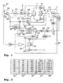
- FIG. 1 shows a transmission chain according to the invention.
- This emission chain is especially intended for use in the field of mobile telephony.
- This chain has three phase locked loops noted 1 to 3.
- the first loop 1 is a so-called intermediate frequency loop and it produces at its output 4 a signal at an intermediate frequency.
- the second loop 2 is a loop at a translation frequency and produces at its output 5 a signal at a translation frequency.
- the third loop is the loop transmission, it produces at its output 6 a signal at a transmission frequency.
- the signal available at output 4 will have a frequency of the order of 100 MHz
- the one available at output 5 will have a frequency of around 1700 MHz.
- the value of the transmission frequency is thus formed additively by the value of the intermediate frequency and the translation frequency.
- the transmission frequency is therefore around 1800 MHz (with variations according to the frequency allocations granted to an operator of telecommunications). Within the framework of GSM these values must be modified so that the transmission frequency is worth 900 MHz.
- the transmission frequency by a subtraction, by the value of the intermediate frequency, of the value of the translation frequency.
- the terminology of additive formation since the translation frequency would then be the result of the addition of the transmission frequency and the intermediate frequency.
- the emission chain of the invention also includes a circuit modulator 7 interposed in the connections between these loops.
- the modulator circuit 7 is interposed in the connection between loop 1 and loop 3. It could nevertheless be interposed between any loops.
- the goal is to modulate the signal available at the transmission frequency by a signal modulating to transmit.
- the modulating signal to be transmitted represents the information. It is here an analog signal with two components I and Q (as well as its values NI and NQ).
- the available intermediate frequency signal at the output 4 is introduced on a phase shifter by 90 degrees 8 whose outputs, 90 ° out of phase with each other, attacking mixers 9 and 10.
- the 90 ° phase shifter comprises a double divider of frequency by two triggered respectively by a rising edge and an edge falling from the intermediate frequency signal.
- the frequency of signal retained at intermediate frequency is, for this reason, double that mentioned so far.
- the phase-shifted components of 90 ° of the intermediate frequency signal mixes with the I and Q signals respectively.
- the outputs of mixers 9 and 10 are combined together in an adder 11 which delivers a modulated signal.
- modulator circuit Any other type of modulator circuit would of course be possible. In particular, the place of this modulator circuit could be different. In in some cases, the modulator circuit is placed in the transmission loop.
- the frequency setting of loops 1 and 2 is obtained by production of a reference signal produced by a reference circuit 12.
- the signal produced by reference 12 has a Fref frequency of 13 MHz. This signal could however have any other value.
- the circuit 12 of reference comprises a quartz.
- the signal of reference 12 is introduced, in particular by dividers 13 and 14, of value Mi and Ms, on the input inputs of phase comparators 15 and 16 of the loops 1 and 2 respectively.
- the phase 15 and 16 comparators also receive output signals delivered by two voltage controlled oscillators 17 and 18 of these loops and which have been divided by dividers 19 and 20 of value Ni and Ns in loops 1 and 2 respectively.
- the signal available at the output of the divider 13 will then have a frequency of 1 MHz.
- the signal delivered by the phase comparator 15 will therefore control oscillator 17 so that the result of the division by Ni of the signal produced by this oscillator 17 also be a 1 MHz signal. Consequently, the signal available on output 4 will have a Ni frequency x 1MHz.
- the operation of a loop is output a signal whose frequency is the product of the frequency of the setpoint signal by the division coefficient of the loop.
- the oscillator 17 comprises, in a known manner, an output connected to the input of the divider 19 and at the input of the modulator circuit 7. This output delivers the signal to the intermediate frequency.
- the frequency of the frequency translation loop 2 setpoint signal had to must be displayed at this low value.
- the divisor coefficient Ns of divisor 20 was high. In one example it was worth 8500 to transform a signal at 1700 MHz into a signal with a frequency comparable to 200 KHz.
- the transmit frequency available at output 6 is the result of adding the signal frequency available at output 4 with the signal frequency available at output 5.
- the intermediate frequency regulation loop 1 had a value fixed in frequency.
- the signal available in this loop has a frequency which varies during frequency jumps.
- the addition of the two signals is preferably caused in the third loop 3 as follows.
- the loop 3 also includes an oscillator 21 voltage controlled.
- the output 6 of the oscillator 21 is connected to a device transmission comprising an amplifier 23, a duplexer 24 and an overhead 25.
- the signal available at output 6 is also picked up by a sensor 26 before amplification.
- This sampled signal is mixed in a mixer 27 with the signal available at output 5 of loop 2.
- the signal resulting from the mixing by the mixer 27, available at an outlet 28 is injected in a phase comparator 29 where it is compared to the signal delivered by the transmission chain 7, therefore, as regards the carrier of the frequency transmission, by the intermediate frequency loop 1.
- the mixer 27 performs subtracting and adding the frequencies of the signals available at output 6 and at output 5. With a low pass filter 33, the addition component is eliminated.
- the signal delivered by the comparator 29 which controls the oscillator 21 has the effect that the result of this subtraction must be equal to the signal at the frequency intermediate, to within the I and Q modul
- the phase comparators 15, 16 and 29 are connected to the oscillators voltage controlled 17, 18 and 21 via low pass filters respectively 30, 31 and 32.
- the filter 30 has a low cut-off frequency of around 100 KHz.
- the filter 31 has a low cut-off frequency of the order of 100 to 200 KHz.
- Filter 32 has a low cut-off frequency of the order of 200 to 300 KHz.
- the cutoff frequency of the filter 33 is of the order of 200 MHz.
- Filters 30 to 33 are loop filters.
- the dividers 13, 14, 19 and 20 are essentially programmable. We easily know how to make such dividers using in their principles counters with automatic reset and retrigger as soon as they reach a pre-recorded value.
- the signal from retriggering these counters represents the frequency divided signal.
- the prerecorded value represents the division coefficient.
- Figure 2 shows a table to explain simply, from a encrypted manner, the operation of the invention.
- a first column 34 indicates possible values of the division coefficient Ni of the divisor 19.
- a second column 35 indicates the value of the intermediate frequency available accordingly at exit 4.
- a third column 36 gives the value of the divisor coefficient of divisor 20.
- a fourth column 37 indicates the signal frequency at the translation frequency available at output 5.
- a last column 38 indicates the value of the frequency of the transmission signal resulting.
- the coefficient Mi of divider 13 is equal to 13 so that the frequency of the setpoint signal admitted to the comparator 15 input is worth 1 MHz. But the explanation remains valid if this coefficient Mi has a different value.
- the coefficient Ni is fixed at the value 98
- the frequency of the signal introduced on the other input of comparator 15 will be worth the value of the frequency delivered by the oscillator 17 divided by 98.
- a times compared by comparator 15, then filtered by filter 30, the resulting signal of the comparison is fed back to the oscillator 17 as a command.
- Ni is 98
- the frequency of the signal available at output 4 is a signal at a frequency of 98 MHz (98x1 MHz).
- the divider 14 has an equal division coefficient Ms to 5. He too could have another value, however.
- the signal allowed on the setpoint input of phase comparator 16 is 2.6 MHz.
- the signal available at output 5 of oscillator 18 will be worth this setpoint, 2.6 MHz, multiplied by the coefficient Ms.
- step A of variation of the coefficient Ni causes a step "a" of frequency variation of the intermediate frequency of 5 MHz.
- a step B of 2 units of Ns causes a frequency step "b" of 5.2 MHz from the frequency of translation.
- the transmission frequency then changes with a frequency step b-a, equal to 200 KHz in the example.
- the translation frequency Ft is equal to Fref * Ns / Ms.
- the frequency intermediate Fi equals Fref * Ni / Mi.
- b Fref * ⁇ NS / Ms
- a Fref * ⁇ Ni / mi.
- ⁇ Ns is the step B then that ⁇ Ni is the step A.
- a / b (B / Ms) / (A / Mi).
- the Mi / Ms ratio of the divisor coefficients of the divisors 13 and 14 respectively is equal or proportional to Ab / aB.
- Figure 1 also schematically shows another characteristic important of the invention represented in the form of a gray area 39.
- the shaded area 39 shows all the modulator equipment which can be integrated on the same integrated circuit. Apart from filters 30 to 33 as well as voltage controlled oscillators 18 and 21, all circuits to date can be integrated on the same integrated circuit 39. This leads to having architecture at very low cost. Even oscillator 17 can be integrated on the integrated circuit 39.
- a frequency divider 40 by two is placed in cascade.
- the divider 40 is switchable. It allows to divide, or not to divide, by two the frequency of signal at the translation frequency. In practice, such a divider 40 can allow to switch from the DCS protocol (1800 MHz) to the GSM protocol (900 MHz) without having to design a doubled circuit.
- the divider 40 is also preferably integrated on the circuit 39.
- Figure 1 also shows that at the output of the duplexer 24 can be connected a reception circuit comprising a demodulator 41 producing the signals I and Q (or NI, and NQ) by mixing, in mixers 42 and 43, the received signal with a signal produced by loop 2 and passing through a phase shifter by 90 degrees 44.
- the noise problem is less crucial in reception.
- loops 1 and 3 are deactivated and loop 2 produces directly a signal at the receiving frequency.
- the divider 14 will be assigned a divisor Ms equal to 65 to produce a frequency comparison of 200 KHz, while the divider Ns will be worth 8500 so that the oscillator 18 produces a signal of the order of 1800 MHz in the context of the DCS.
- demodulation is direct, without going through a step to intermediate frequency.
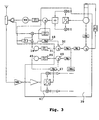
- FIG 3 shows the same elements as Figure 1 with the difference however that oscillator 18 is not going to have to have too much dynamic important.
- an oscillator 18 to be used for transmission and whose variation range will typically be between 1530 and 1654 MHz, in the case of DCS, while an oscillator 45 used for reception will have a range evolving between 1805 and 1920 MHz in the case of DCS also.
- the oscillator 18 should have a dynamic to cover the reception band and the transmission band, added to a value of channel separation. Indeed, as part of the GSM type telephony, the transmit and receive channels are separated each other.
- the transmission and reception channels each have a 35 MHz band and are spaced 10 MHz apart.
- the two oscillators 18 and 45 each of them may have a lower frequency variation dynamic.
- loop 2 is split to serve on the one hand in transmission with the filter 31 and oscillator 18, and on the other hand in reception with a filter 46 and oscillator 45.
- the cut-off frequency of the low-pass filter 46 can be of the order of 5 to 10 KHz.
- dividers 47 and 48 and the phase comparators 49 and 50 of each of these loops are incorporated in the integrated circuit 39.
- This architecture has especially the advantage that the dividers 47 and 48 can be conditioned in advance, even before use, as soon as actually knows the carrier frequency in which they must participate.
- the evolution in frequency during the jumps results from the processing of an algorithm stored in mobile phones.
- These can therefore according to the invention, anticipate the processing of this algorithm, define carrier frequencies usable in windows future temporal values, deduce the values of the coefficients of the divisors, and the impose on these dividers with enough time advance so that the regulated frequency in each of the translation loops is well stabilized at when it should be used. Having two loops of translation allows for example to start conditioning one of these loops while the other is at work. So we don't have to wait until this other loop has finished.
Landscapes
- Engineering & Computer Science (AREA)
- Power Engineering (AREA)
- Stabilization Of Oscillater, Synchronisation, Frequency Synthesizers (AREA)
- Transmitters (AREA)
- Transceivers (AREA)
- Mobile Radio Communication Systems (AREA)
Claims (9)
- Sendekette, insbesondere für ein Mobiltelefon, die einen ersten (1), einen zweiten (2) und einen dritten (3) Phasenregelkreis (PLL-Schaltkreis) (15, 16, 29) umfasst, die untereinander verbunden sind, um jeweils ein Signal mit einer Zwischenfrequenz, ein Signal mit einer Umsetzungsfrequenz bzw. ein Signal mit einer Sendefrequenz zu erzeugen (4, 5, 6), wobei der Wert der Sendefrequenz gleich der Summe der Werte von Zwischenfrequenz und Umsetzungsfrequenz ist, dadurch gekennzeichnet, dass die Werte von Zwischenfrequenz und Umsetzungsfrequenz durch Teilungsschaltungen (19, 20) programmierbar sind (Ni, Ns), und dadurch, dass die Veränderungen der Faktoren dieser Teilungsschaltungen untereinander durch eine Änderung der zu erhaltenden Sendefrequenz verknüpft sind.
- Kette nach Anspruch 1, dadurch gekennzeichnet, dassder erste Regelkreis einen ersten Frequenzteiler mit einer ersten Vergleichsfrequenz fc1 aufweist, dessen Faktor sich mit einem Änderungsschritt A entwickelt und einen Frequenzschritt a gleich A.fc1 auslöst;der zweite Regelkreis einen zweiten Frequenzteiler mit einer zweiten Vergleichsfrequenz fc2 aufweist, dessen Faktor sich mit einem Änderungsschritt B entwickelt und einen Frequenzschritt b gleich B.fc2 auslöst;in der Weise, dass ein Änderungsschritt b-a oder a-b der Sendefrequenz ausgelöst wird.
- Kette nach Anspruch 2, dadurch gekennzeichnet, dass sie einen Frequenzbezugskreis (12), einen dritten Frequenzteiler (13), der mit diesem Bezugskreis zur Steuerung des ersten Regelkreises verbunden ist, und einen vierten Frequenzteiler (14), der mit diesem Bezugskreis zur Steuerung des zweiten Regelkreises verbunden ist, aufweist, wobei die Teilungsfaktoren Mi und Ms des dritten und vierten Teilers im Verhältnis Mi/Ms proportional zu oder gleich Ab/aB sind.
- Kette nach einem der Ansprüche 1 bis 3, dadurch gekennzeichnet, dass jeder der ersten und zweiten Regelkreise in Reihe geschaltet einen Oszillator, einen Frequenzteiler, einen Phasenkomparator und ein Tiefpassfilter aufweist, und dadurch, dass diese Frequenzteiler und Phasenkomparatoren auf einer integrierten Schaltung (39) integriert sind, die außerdem den Phasenkomparator des dritten Regelkreises enthält.
- Kette nach einem der Ansprüche 1 bis 4, dadurch gekennzeichnet, dass sie einen Modulatorkreis (7) aufweist, der in die Verbindung zwischen dem Zwischenfrequenzregelkreis und dem Sendefrequenzregelkreis zwischengeschaltet ist und der vorzugsweise auf derselben integrierten Schaltung integriert ist wie jener, welche den ersten und den zweiten Regelkreis enthält.
- Kette nach einem der Ansprüche 1 bis 5, dadurch gekennzeichnet, dass sie einen mit dem zweiten Regelkreis verbundenen Demodulatorkreis (41) und einen Satz aus zwei Schleifenfiltern (31, 46) aufweist, die mit dem zweiten Regelkreis durch einen Satz von zwei Umschaltern (51, 52) verbunden sind, wobei dieser Demodulatorkreis und diese beiden Umschalter vorzugsweise auf derselben integrierten Schaltung integriert sind wie jener, welche den ersten und den zweiten Regelkreis enthält.
- Kette nach einem der Ansprüche 1 bis 6, dadurch gekennzeichnet, dass der dritte Regelkreis einen Frequenzteiler (40) aufweist, der eine Teilung durch zwei durchführt und so umschaltbar ist, dass er für eine Nutzung im GSM- oder im DCS-Modus geeignet ist.
- Sendeverfahren, insbesondere für ein Mobiltelefon, das die folgenden Schritte aufweist:dadurch gekennzeichnet, dass man den Wert der Zwischenfrequenz abnehmen lässt (35), während man gleichzeitig den Wert der Umsetzungsfrequenz ansteigen lässt (37), oder umgekehrt, und zwar in der Weise, dass eine Änderung der Sendefrequenz durch diese Anstiegs- und Abnahmedifferenzen hervorgerufen wird.ein erster (1), ein zweiter (2) und ein dritter (3) Phasenregelkreis (PLL-Schaltkreis) werden in Betrieb gesetzt, um jeweils ein Signal mit einer Zwischenfrequenz, ein Signal mit einer Umsetzungsfrequenz und ein Signal mit einer Sendefrequenz zu erzeugen (4, 5, 6);die drei Regelkreise werden untereinander verbunden, damit der Wert der Sendefrequenz gleich der Summe der Werte der Zwischenfrequenz und der Umsetzungsfrequenz ist;
- Verfahren nach Anspruch 8, dadurch gekennzeichnet, dass man den Wert der Umsetzungsfrequenz mit einem Schritt gleich b ansteigen lässt, und dass man den Wert der Zwischenfrequenz mit einem Schritt von a ansteigen lässt, damit die Sendefrequenz um einen Schritt von a-b ansteigt.
Priority Applications (1)
| Application Number | Priority Date | Filing Date | Title |
|---|---|---|---|
| EP04018081A EP1482635B1 (de) | 1998-06-11 | 1999-06-10 | Sende-Empfänger und Verfahren |
Applications Claiming Priority (2)
| Application Number | Priority Date | Filing Date | Title |
|---|---|---|---|
| FR9807340A FR2779890B1 (fr) | 1998-06-11 | 1998-06-11 | Chaine d'emission reception et procede d'emission notamment pour un telephone mobile |
| FR9807340 | 1998-06-11 |
Related Child Applications (2)
| Application Number | Title | Priority Date | Filing Date |
|---|---|---|---|
| EP04018081A Division EP1482635B1 (de) | 1998-06-11 | 1999-06-10 | Sende-Empfänger und Verfahren |
| EP04018081.2 Division-Into | 2004-07-30 |
Publications (2)
| Publication Number | Publication Date |
|---|---|
| EP0964523A1 EP0964523A1 (de) | 1999-12-15 |
| EP0964523B1 true EP0964523B1 (de) | 2004-12-15 |
Family
ID=9527257
Family Applications (2)
| Application Number | Title | Priority Date | Filing Date |
|---|---|---|---|
| EP04018081A Expired - Lifetime EP1482635B1 (de) | 1998-06-11 | 1999-06-10 | Sende-Empfänger und Verfahren |
| EP99401396A Expired - Lifetime EP0964523B1 (de) | 1998-06-11 | 1999-06-10 | Hochfrequenzumsetzer |
Family Applications Before (1)
| Application Number | Title | Priority Date | Filing Date |
|---|---|---|---|
| EP04018081A Expired - Lifetime EP1482635B1 (de) | 1998-06-11 | 1999-06-10 | Sende-Empfänger und Verfahren |
Country Status (8)
| Country | Link |
|---|---|
| US (1) | US6161000A (de) |
| EP (2) | EP1482635B1 (de) |
| JP (1) | JP2000031898A (de) |
| AU (1) | AU744555B2 (de) |
| CA (1) | CA2272077A1 (de) |
| DE (2) | DE69922584T2 (de) |
| ES (2) | ES2312891T3 (de) |
| FR (1) | FR2779890B1 (de) |
Families Citing this family (15)
| Publication number | Priority date | Publication date | Assignee | Title |
|---|---|---|---|---|
| US6091303A (en) * | 1999-04-06 | 2000-07-18 | Ericsson Inc. | Method and apparatus for reducing oscillator noise by noise-feedforward |
| US6912376B1 (en) * | 1999-12-27 | 2005-06-28 | Texas Instruments Incorporated | Mobile phone transceiver |
| DE60041784D1 (de) | 2000-01-11 | 2009-04-23 | Ttp Communications Ltd | Sender und Funkkommunikationsendgerät damit |
| EP1255356B1 (de) * | 2001-05-02 | 2009-07-22 | Sony Deutschland GmbH | Dualmode-Dreiband-Frequenzsynthesizer |
| EP1320189B1 (de) | 2001-12-12 | 2007-07-11 | Sony Deutschland GmbH | Mehrband-Frequenzsynthesizer für mobile Endgeräte |
| KR100439221B1 (ko) * | 2002-04-12 | 2004-07-05 | 엘지전자 주식회사 | 이동통신시스템의 송신장치 |
| US7133354B2 (en) * | 2002-08-26 | 2006-11-07 | Qualcomm Incorporated | Synchronization techniques for a wireless system |
| US7388845B2 (en) * | 2002-08-26 | 2008-06-17 | Qualcomm Incorporated | Multiple access wireless communications system using a multisector configuration |
| US7366200B2 (en) * | 2002-08-26 | 2008-04-29 | Qualcomm Incorporated | Beacon signaling in a wireless system |
| US6985498B2 (en) | 2002-08-26 | 2006-01-10 | Flarion Technologies, Inc. | Beacon signaling in a wireless system |
| ATE363159T1 (de) * | 2003-03-11 | 2007-06-15 | Sony Ericsson Mobile Comm Ab | Mehrband-frequenzsynthetisierer |
| RU2263962C1 (ru) * | 2004-05-06 | 2005-11-10 | Заренков Вячеслав Адамович | Система для проведения безналичных финансовых операций |
| US7379446B2 (en) * | 2004-10-14 | 2008-05-27 | Qualcomm Incorporated | Enhanced beacon signaling method and apparatus |
| US7715845B2 (en) | 2004-10-14 | 2010-05-11 | Qualcomm Incorporated | Tone hopping methods and apparatus |
| US8351405B2 (en) * | 2006-07-14 | 2013-01-08 | Qualcomm Incorporated | Method and apparatus for signaling beacons in a communication system |
Family Cites Families (16)
| Publication number | Priority date | Publication date | Assignee | Title |
|---|---|---|---|---|
| US4313209A (en) * | 1980-07-14 | 1982-01-26 | John Fluke Mfg. Co., Inc. | Phase-locked loop frequency synthesizer including compensated phase and frequency modulation |
| US5038404A (en) * | 1989-09-01 | 1991-08-06 | General Instrument Corp. | Low phase noise agile up converter |
| US5055802A (en) * | 1990-04-30 | 1991-10-08 | Motorola, Inc. | Multiaccumulator sigma-delta fractional-n synthesis |
| GB2247368B (en) * | 1990-08-25 | 1994-08-24 | Roke Manor Research | Phase modulation signal generator |
| US5128633A (en) * | 1991-07-08 | 1992-07-07 | Motorola, Inc. | Multi-loop synthesizer |
| US5130676A (en) * | 1991-09-06 | 1992-07-14 | Motorola, Inc. | Phase locked loop frequency synthesizer with DC data modulation capability |
| JP2526847B2 (ja) * | 1993-05-24 | 1996-08-21 | 日本電気株式会社 | ディジタル方式無線電話機 |
| US5390346A (en) * | 1994-01-21 | 1995-02-14 | General Instrument Corporation Of Delaware | Small frequency step up or down converters using large frequency step synthesizers |
| FI941862A7 (fi) * | 1994-04-21 | 1995-10-22 | Nokia Mobile Phones Ltd | Menetelmä ja radiotaajuusjärjestelmä kahden eri taajuusalueella toimivan radioviestinjärjestelmän vastaanottimen ja lähettimen taajuuksien muodostamiseksi ja kahdella eri taajuusalueella toimiva vastaanotin ja lähetin sekä edellisten käyttö matkapuhelimessa |
| US5572168A (en) * | 1995-08-09 | 1996-11-05 | Lucent Technologies Inc. | Frequency synthesizer having dual phase locked loops |
| JPH1022852A (ja) * | 1996-07-02 | 1998-01-23 | Nec Corp | 無線通信装置 |
| US5898906A (en) * | 1996-10-29 | 1999-04-27 | Gec Plessey Semiconductors, Inc. | System and method for implementing a cellular radio transmitter device |
| US6008703A (en) * | 1997-01-31 | 1999-12-28 | Massachusetts Institute Of Technology | Digital compensation for wideband modulation of a phase locked loop frequency synthesizer |
| US6009312A (en) * | 1997-02-05 | 1999-12-28 | Ericsson Inc. | Transmit signal generation with the aid of a receiver |
| US5963852A (en) * | 1997-03-24 | 1999-10-05 | Ericsson Inc. | Dual band mobile station |
| US5991632A (en) * | 1997-04-04 | 1999-11-23 | Casio Phonemate, Inc. | Cordless telephone and method of synchronization for secure, high-speed, high-volume data transfer |
-
1998
- 1998-06-11 FR FR9807340A patent/FR2779890B1/fr not_active Expired - Fee Related
-
1999
- 1999-05-17 CA CA002272077A patent/CA2272077A1/fr not_active Abandoned
- 1999-06-09 AU AU33967/99A patent/AU744555B2/en not_active Ceased
- 1999-06-09 JP JP11162765A patent/JP2000031898A/ja active Pending
- 1999-06-10 EP EP04018081A patent/EP1482635B1/de not_active Expired - Lifetime
- 1999-06-10 DE DE69922584T patent/DE69922584T2/de not_active Expired - Lifetime
- 1999-06-10 US US09/328,598 patent/US6161000A/en not_active Expired - Lifetime
- 1999-06-10 ES ES04018081T patent/ES2312891T3/es not_active Expired - Lifetime
- 1999-06-10 ES ES99401396T patent/ES2235448T3/es not_active Expired - Lifetime
- 1999-06-10 EP EP99401396A patent/EP0964523B1/de not_active Expired - Lifetime
- 1999-06-10 DE DE69939280T patent/DE69939280D1/de not_active Expired - Lifetime
Also Published As
| Publication number | Publication date |
|---|---|
| DE69922584D1 (de) | 2005-01-20 |
| JP2000031898A (ja) | 2000-01-28 |
| EP0964523A1 (de) | 1999-12-15 |
| EP1482635A3 (de) | 2005-01-19 |
| ES2312891T3 (es) | 2009-03-01 |
| DE69939280D1 (de) | 2008-09-18 |
| DE69922584T2 (de) | 2005-12-22 |
| AU3396799A (en) | 1999-12-23 |
| CA2272077A1 (fr) | 1999-12-11 |
| US6161000A (en) | 2000-12-12 |
| AU744555B2 (en) | 2002-02-28 |
| FR2779890A1 (fr) | 1999-12-17 |
| EP1482635A2 (de) | 2004-12-01 |
| ES2235448T3 (es) | 2005-07-01 |
| FR2779890B1 (fr) | 2000-08-04 |
| EP1482635B1 (de) | 2008-08-06 |
Similar Documents
| Publication | Publication Date | Title |
|---|---|---|
| EP1482635B1 (de) | Sende-Empfänger und Verfahren | |
| EP0624959B1 (de) | FM-Empfänger mit einer Schaltung zur Überabtastung | |
| FI90169C (fi) | Foerfarande och kopplingsarrangemang foer att alstra en modulerad signal | |
| EP1555757A1 (de) | RF-integrierte Schaltung mit einem Frequenzsynthesizer geringer Empfindlichkeit gegen den Effekt des Mitziehens der Frequenz | |
| FR2666464A1 (fr) | Procede et appareil de synthese de frequence a n fractionnaire avec accumulateurs multiples a memorisation temporaire et application a un radioemetteur. | |
| EP0746114B1 (de) | Frequenzmodulierter Funksender | |
| FR2798019A1 (fr) | Synthetiseur de frequences a boucle de phase | |
| FR2580885A1 (fr) | Systeme pour la transmission secrete de signaux audio, et televiseur pour la reception de tels signaux | |
| FR2755556A1 (fr) | Modulateur de frequence, emetteur et emetteur-recepteur incorporant ce modulateur de frequence | |
| EP0661816B1 (de) | Einzelschleifenfrequenzsynthetisierer und einen solchen Synthetisierer enthaltende elektronische Anordnung | |
| JPH03505959A (ja) | デジタル差動位相変調デコーダ | |
| FR2798790A1 (fr) | Dispositif de synthese de frequence | |
| EP1193877A1 (de) | Frequenzsynthesizer mit gebrochenem Teilverhältnis und schneller Abstimmung und entsprechendes Verfahren zur Frequenzsynthese | |
| FR2786342A1 (fr) | Synthetiseur de frequence et procede de saut de frequence double avec un temps de verrouillage rapide | |
| EP0434527B1 (de) | Mikrowellen-Synthesierer mit einem Teiler mit gebrochenem Teilverhältnis | |
| EP1710916B1 (de) | Phasenregelschleife | |
| US5642385A (en) | Frequency detector for carrier frequency synchronization | |
| BE1010980A3 (fr) | Synthetiseur de frequence a boucle de verrouillage de phase a division fractionnaire multiple. | |
| FR2795280A1 (fr) | Telephone mobile comportant un dispositif d'emission d'un signal module en phase et en amplitude et son procede associe | |
| FR3006130A1 (fr) | Dispositif et procede de synthese de frequences | |
| FR2561468A1 (fr) | Filtre actif hyperfrequence | |
| FR2533319A1 (fr) | Emetteur radar | |
| EP1052772A1 (de) | Schaltung und Verfahren zur Erzeugung eines gefilterten Signals | |
| EP1424778B1 (de) | Vorrichtung und dazugehöriges Verfahren zur Erzeugung einer Frequenz mit hoher spektraler Reinheit | |
| EP1411638B1 (de) | Verfahren und Vorrichtung zur Erzeugung eines Signals mit einer dem Produkt einer Referenzfrequenz mit einer reellen Zahl entsprechenden Frequenz |
Legal Events
| Date | Code | Title | Description |
|---|---|---|---|
| PUAI | Public reference made under article 153(3) epc to a published international application that has entered the european phase |
Free format text: ORIGINAL CODE: 0009012 |
|
| AK | Designated contracting states |
Kind code of ref document: A1 Designated state(s): DE ES FR GB IT SE |
|
| AX | Request for extension of the european patent |
Free format text: AL;LT;LV;MK;RO;SI |
|
| 17P | Request for examination filed |
Effective date: 20000615 |
|
| AKX | Designation fees paid |
Free format text: DE ES FR GB IT SE |
|
| 17Q | First examination report despatched |
Effective date: 20030131 |
|
| GRAP | Despatch of communication of intention to grant a patent |
Free format text: ORIGINAL CODE: EPIDOSNIGR1 |
|
| GRAS | Grant fee paid |
Free format text: ORIGINAL CODE: EPIDOSNIGR3 |
|
| GRAA | (expected) grant |
Free format text: ORIGINAL CODE: 0009210 |
|
| AK | Designated contracting states |
Kind code of ref document: B1 Designated state(s): DE ES FR GB IT SE |
|
| REG | Reference to a national code |
Ref country code: GB Ref legal event code: FG4D Free format text: NOT ENGLISH |
|
| REF | Corresponds to: |
Ref document number: 69922584 Country of ref document: DE Date of ref document: 20050120 Kind code of ref document: P |
|
| PG25 | Lapsed in a contracting state [announced via postgrant information from national office to epo] |
Ref country code: SE Free format text: LAPSE BECAUSE OF FAILURE TO SUBMIT A TRANSLATION OF THE DESCRIPTION OR TO PAY THE FEE WITHIN THE PRESCRIBED TIME-LIMIT Effective date: 20050315 |
|
| GBT | Gb: translation of ep patent filed (gb section 77(6)(a)/1977) |
Effective date: 20050330 |
|
| REG | Reference to a national code |
Ref country code: ES Ref legal event code: FG2A Ref document number: 2235448 Country of ref document: ES Kind code of ref document: T3 |
|
| PLBE | No opposition filed within time limit |
Free format text: ORIGINAL CODE: 0009261 |
|
| STAA | Information on the status of an ep patent application or granted ep patent |
Free format text: STATUS: NO OPPOSITION FILED WITHIN TIME LIMIT |
|
| 26N | No opposition filed |
Effective date: 20050916 |
|
| REG | Reference to a national code |
Ref country code: FR Ref legal event code: TP |
|
| REG | Reference to a national code |
Ref country code: GB Ref legal event code: 732E |
|
| REG | Reference to a national code |
Ref country code: GB Ref legal event code: 732E Free format text: REGISTERED BETWEEN 20090924 AND 20090930 |
|
| REG | Reference to a national code |
Ref country code: GB Ref legal event code: 732E Free format text: REGISTERED BETWEEN 20120607 AND 20120613 |
|
| REG | Reference to a national code |
Ref country code: FR Ref legal event code: TP Owner name: Z124, GB Effective date: 20130201 Ref country code: FR Ref legal event code: CD Owner name: Z124, GB Effective date: 20130201 |
|
| REG | Reference to a national code |
Ref country code: FR Ref legal event code: PLFP Year of fee payment: 18 |
|
| REG | Reference to a national code |
Ref country code: FR Ref legal event code: PLFP Year of fee payment: 19 |
|
| PGFP | Annual fee paid to national office [announced via postgrant information from national office to epo] |
Ref country code: GB Payment date: 20170526 Year of fee payment: 19 Ref country code: FR Payment date: 20170523 Year of fee payment: 19 |
|
| PGFP | Annual fee paid to national office [announced via postgrant information from national office to epo] |
Ref country code: DE Payment date: 20180625 Year of fee payment: 20 |
|
| PGFP | Annual fee paid to national office [announced via postgrant information from national office to epo] |
Ref country code: ES Payment date: 20180720 Year of fee payment: 20 Ref country code: IT Payment date: 20180627 Year of fee payment: 20 |
|
| GBPC | Gb: european patent ceased through non-payment of renewal fee |
Effective date: 20180610 |
|
| PG25 | Lapsed in a contracting state [announced via postgrant information from national office to epo] |
Ref country code: FR Free format text: LAPSE BECAUSE OF NON-PAYMENT OF DUE FEES Effective date: 20180630 Ref country code: GB Free format text: LAPSE BECAUSE OF NON-PAYMENT OF DUE FEES Effective date: 20180610 |
|
| REG | Reference to a national code |
Ref country code: DE Ref legal event code: R071 Ref document number: 69922584 Country of ref document: DE |
|
| REG | Reference to a national code |
Ref country code: ES Ref legal event code: FD2A Effective date: 20200803 |
|
| PG25 | Lapsed in a contracting state [announced via postgrant information from national office to epo] |
Ref country code: ES Free format text: LAPSE BECAUSE OF EXPIRATION OF PROTECTION Effective date: 20190611 |