EP0965260A1 - Conditionneur pour faucheuse rotative - Google Patents
Conditionneur pour faucheuse rotative Download PDFInfo
- Publication number
- EP0965260A1 EP0965260A1 EP99110698A EP99110698A EP0965260A1 EP 0965260 A1 EP0965260 A1 EP 0965260A1 EP 99110698 A EP99110698 A EP 99110698A EP 99110698 A EP99110698 A EP 99110698A EP 0965260 A1 EP0965260 A1 EP 0965260A1
- Authority
- EP
- European Patent Office
- Prior art keywords
- axis
- rail
- conditioner
- conditioner according
- impact
- Prior art date
- Legal status (The legal status is an assumption and is not a legal conclusion. Google has not performed a legal analysis and makes no representation as to the accuracy of the status listed.)
- Granted
Links
- 230000007246 mechanism Effects 0.000 claims description 35
- 238000006073 displacement reaction Methods 0.000 claims description 6
- 230000006835 compression Effects 0.000 claims description 3
- 238000007906 compression Methods 0.000 claims description 3
- 230000001105 regulatory effect Effects 0.000 claims 1
- 238000006243 chemical reaction Methods 0.000 abstract 1
- 238000003780 insertion Methods 0.000 abstract 1
- 230000037431 insertion Effects 0.000 abstract 1
- 239000004460 silage Substances 0.000 abstract 1
- 230000008901 benefit Effects 0.000 description 5
- 230000001133 acceleration Effects 0.000 description 4
- 239000004459 forage Substances 0.000 description 4
- 238000003754 machining Methods 0.000 description 4
- 238000000034 method Methods 0.000 description 3
- 230000008569 process Effects 0.000 description 3
- 230000008859 change Effects 0.000 description 2
- 230000001788 irregular Effects 0.000 description 2
- 230000009471 action Effects 0.000 description 1
- 230000002411 adverse Effects 0.000 description 1
- 238000005553 drilling Methods 0.000 description 1
- 238000001035 drying Methods 0.000 description 1
- 239000012530 fluid Substances 0.000 description 1
- 239000000463 material Substances 0.000 description 1
Images


Classifications
-
- A—HUMAN NECESSITIES
- A01—AGRICULTURE; FORESTRY; ANIMAL HUSBANDRY; HUNTING; TRAPPING; FISHING
- A01D—HARVESTING; MOWING
- A01D43/00—Mowers combined with apparatus performing additional operations while mowing
- A01D43/10—Mowers combined with apparatus performing additional operations while mowing with means for crushing or bruising the mown crop
- A01D43/102—Bruising control devices
Definitions
- the invention relates to a conditioner for rotary mowers according to the preamble of claim 1.
- Conditioners take mowed green fodder in one operation with the Mowing process and edit it with rotating tools. This will the green fodder kinked and squeezed, causing the wilting process is accelerated.
- DE 296 07 248 U1 is a conditioner Known for mounting on a rotary mower, which is designed as an articulated tiller.
- the processing tools of buckling machines can be fixed Impact tines or also be designed as movable flail prongs are on a driven rotating shaft, the total form a body of revolution.
- the mowed green fodder is called the green fodder flow by the rotating ones Work tools of the conditioner recorded and guided over them.
- the Machining intensity can be affected by the flow resistance is changeable by the conditioner.
- an impact rail is arranged, which determines the free flow cross-section for the green fodder flow.
- Flow cross-section is defined by the width of the rotating body and due to the gap between the impact rail and the Machining tools as rotating bodies. The gap between the Impact rail and the processing tools can be changed and thus the Green forage ratios are adjusted.
- the gap width can be changed by the impact rail, which is mounted around an axis of rotation in the side walls of the conditioner, is pivoted about this axis by means of an adjusting lever.
- the green fodder flow in ongoing processing of the conditioner can be interrupted. reason this is because the internal binding forces of the green fodder flow are overcome are associated with the acceleration of the flow of green fodder Centrifugal forces. This causes the green fodder to be thrown radially outwards and not led over the processing tools, which leads to the fact that the green fodder falls back and accumulates in front of the rotating body. This then leads to irregular flow of green fodder through the Conditioner so that the mowing is not uniform, but as an irregular one Pile is deposited, which adversely affects the wilting and drying process influenced.
- the object of the invention is to provide an improved conditioner for green fodder to create an adjustment mechanism that enables the Process parameters of the conditioner the properties of the to be processed Adjust green fodder flow to achieve optimal work results can.
- a conditioner according to the invention has an adjustable baffle, so is designed that this is both a sliding and a rotary movement can perform.
- the tangential orientation of the Impact rail, and on the other hand the radial distance of the impact rail in relation changed independently on the axis of rotation of the rotor roller become.
- both the exit gap and the feed gap is variably adjustable between the rotor roller and the impact rail. It is also possible, the width of the feed and exit gap independently to be able to vary from one another. This means that the tangential Angle of attack of the impact rail to the rotor roller can also be varied, whereby the cross section of the guide channel between the boundary wall of the Impact rail and the circumference of the rotor roller is also variable. With a Locking mechanism, the impact rail is locked in its respective position.
- the adjustment mechanism of the impact rail is designed so that the impact rail has two axes of rotation, one on the entry side of the impact rail and on the other hand on the exit side of the impact rail. Because the Baffle rail is also guided in an elongated hole on the entry side, it is possible, the impact rail predominantly in the vertical direction with simultaneous To be able to move and rotate the rotation around the front axis.
- the exit side of the impact rail also has a rotatable axis that also allows rotation and displacement movements around this axis. Consequently can the impact rail within the limits of the adjustment mechanism experience rotating and sliding movements at the same time.
- This configuration of the adjustment mechanism also includes the Baffle rail has the advantage that depending on the type and property of the green fodder subsequent flow cross section of the guide channel can be changed and thereby the processing intensity of the green fodder is particularly effective and can be set variably.
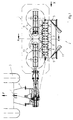
- Fig. 1 shows a rotary mower (1) with conditioner (2) in a plan view of the working level in the direction of travel (F), attached to the rear three-point linkage (4) of a tractor (3).
- Rotary mower (1) and conditioner (2) are driven by the PTO shaft (7) of a tractor (3).
- the rotor shaft (6) with its axis of rotation (14) is mounted in the side walls of the conditioner housing (5) and is equipped with rigid V-shaped striking tines (9) in the circumferential and longitudinal directions.
- the conditioner (2) forms a unit with the rotary mower (1).
- the green fodder is mowed by the mowing rotors (10) and fed to the conditioner (2) for pick-up by the rotor roller (8).
- the rear baffles (11) make it possible to vary the width of the milled material.
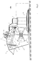
- Fig. 2 shows a view in the direction X "transversely to the direction of travel (F) according to Fig. 1.
- the rotor roller (8) with its striking tines (9) is covered by a conditioner housing (5).
- the rotor shaft (6) is in the side wall (13) of the conditioner housing (5).
- the impact rail (16) is parallel and at a distance from the axis of rotation (14) and is equipped with an adjustment mechanism (17) which enables the radial distance of the impact rail (16) from the axis of rotation (14) change.
- the configuration of the adjustment mechanism (17) enables Change the orientation of the impact rail (16) in the tangential direction related to the axis of rotation (14).
- the adjustment mechanism (17) is located on both sides of the side walls (13) outside the conditioner housing (5), this adjustment mechanism (17) with the baffle rail (16) located inside the conditioner housing (5) for Adjustment in its radial and tangential alignment in operative connection stands.
- the adjustment mechanism (17) consists of an adjustment lever (18), which in its angle of rotation limited by a bearing pin (19) adjustable and thus is pivotally mounted.
- the bearing pin (19) is on the side wall (13) of the Conditioner housing (5) fastens and supports the adjustment lever (18) both in from its locked position as well as during its adjustment movement.
- the adjustment levers (18) are locked with a spring-loaded snap bolt (20), which is fixed to the adjusting lever (18) and which in one of the bores (22) one Segment sheet (21) engages.
- the slide levers (26) are each in one Hinge point (28) with the impact rail (16) at the ends of its longitudinal extent articulated.
- the connection of the articulation points (28) of the two Slide levers (26) also form a pivot axis (41 ') of the impact rail (16).
- the slide levers (26) are in Guide pockets (29), which are equipped with a lead-through opening (30) are staked out with plug pins (31).
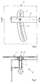
- Fig. 3 shows the detail Y "in Fig. 2 and thus the locking mechanism of the adjusting lever (18) in an enlarged view.
- Fig. 4 shows the section BB in Fig. 3 as an example of an embodiment of a locking mechanism (18) with the snap bolt (20), which is under tension with a compression spring (12).
- Fig. 5 shows the detail Z "in Fig. 2 and thus the guide mechanism of the adjusting lever (18) for the impact rail (16) in an enlarged view.
- Fig. 6 shows the section CC in Fig. 5 as an example of an embodiment by the guide mechanism of the impact rail (16).
- Fig. 7 shows the section DD in Fig. 2 as an example of an embodiment of the locking of the slide lever (26).
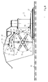
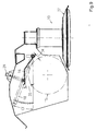
- Fig. 8 shows the section AA in Fig. 1 with the impact rail (16) in the central position of the setting range.
- the orientation and arrangement of the baffle rail (16) determines the flow resistance and thus the processing intensity for the processing of the green fodder.
- the orientation of the impact rail (16) is characterized by the angle ( ⁇ ), this angle ( ⁇ ) being defined by the position of two planes relative to one another, on the one hand by the plane which is defined by the pivot axes (41, 41 '), and on the other hand through a plane parallel to the working plane (42).
- the arrangement and orientation of the impact rail (16) is characterized by the respective radius and thus by the distance between the pivot axis (41, 41 ') and the axis of rotation (14).
- the arrangement and orientation of the impact rail (16) determine the size of the Feed cross section (32) with its feed gap width and the size of the Outlet cross section (33) with its outlet gap width (35).
- the green fodder flow (36) is from the tines (9) of the rotor roller (8) the mower discs (37) of the mower rotor (10) and then in the further Course of his flow movement through the intake cross section (32) with his Feed gap width (34) conveyed through.
- the green fodder of the green fodder flow thus experiences a tangential and a radial acceleration at the same time Centrifugal acceleration.
- the centrifugal acceleration is the cause of the green fodder these accelerated movements on its trajectory around the Axis of rotation (14) not only tangentially but also radially and thus to is moved outside of the axis of rotation (14).
- the impact rail (16) limits the radial direction of movement with respect to the axis of rotation (14) and presses the green fodder against the tines (9) or into the Spaces (38) between the striking tines (9) of the rotor roller (8).
- the tangential alignment of the impact rail (16) with respect to the rotor roller (8) also influences the flow resistance and thus the Duration of action of the impact tines (9) on the green forage of the green forage flow (36).
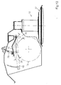
- Fig. 9 shows the section AA in Fig. 1 with the impact rail (16) in the minimum position of the setting range.
- the impact rail (16) is positioned by the adjusting mechanism (17) relative to the rotor roller (8) and locked in relation to the conditioner housing (5) in such a way that the inlet (34) and outlet gap (35) are minimal.
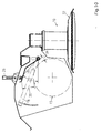
- Fig. 10 shows the section AA in Fig. 1 with the impact rail (16) in the min-max position of the setting range.
- the impact rail (16) is positioned by the adjusting mechanism (17) relative to the rotor roller (8) and locked relative to the conditioner housing (5) in such a way that the feed gap width (34) is minimal and the exit gap width (35) is maximum.
- Fig. 11 shows the section AA in Fig. 1 with the impact rail (16) in the max-max position of the adjustment range.
- the impact rail (16) is positioned by the adjustment mechanism (17) relative to the rotor roller (8) and locked in relation to the conditioner housing (5) in such a way that the inlet (34) and outlet gap (35) are maximum.
- Fig. 12 shows the section AA in Fig. 1 with the impact rail (16) max-min position of the setting range.
- the impact rail (16) is positioned by the adjusting mechanism (17) in relation to the rotor roller (8) and in relation to the
- Conditioner housing (5) locked so that the feed gap width (35) maximum and the outlet gap width (34) is minimal.
- This processing intensity can be adjusted by the changeable design of the guide channel (39), which is formed by the impact rail (16) with its inner boundary wall (40) and the envelope surface the rotor roller (8), formed from the flight circles (15) of the ends of the Impact tines (9) of the rotor roller (8).
- This guide channel (39) has an influence on the guidance of the green fodder flow (36) by the green fodder more or less deep into the spaces (38) of the rotor roller (8) between the Impact tines (9) can penetrate.
- the changeable design of the guide channel (39) is marked due to the variability of the feed gap width (34), the exit gap width (35) and the angle of attack ( ⁇ ). This makes it possible, on the one hand, the radial one Distance and the tangential alignment of the impact rail (16) with to vary the angle of attack ( ⁇ ) independently of one another.
- a particular advantage of the invention is that in addition to Adjustment of the processing intensity, the feed gap width (34) can be changed which is particularly advantageous when the feed stock is low.
- the adjustment mechanism (17) can in principle also be operated by remote control motorized actuators which can be actuated by auxiliary energy, for example Hydraulic cylinders pressurized with fluid can be controlled.
- auxiliary energy for example Hydraulic cylinders pressurized with fluid
- the location and Alignment of the impact rail (16) can be done, for example, by means of sensors be queried. whose signals a microprocessor in the sense of a Control chain or a control loop are supplied. These signals can be used to display the data on the user station in the Driver's cabin the current state and thus the arrangement and alignment of the Show impact rail (16) so that the driver of the tractor (3) as Information is visibly available. Using appropriate controls can the arrangement and alignment of the impact rail (16) by the driver of the Tractor (3) can be changed.
- Rotary mower with conditioner according to the invention can be used as attached devices in the rear or front attachment mode or as attached devices from a tractor operate.
Landscapes
- Life Sciences & Earth Sciences (AREA)
- Environmental Sciences (AREA)
- Harvester Elements (AREA)
- Guiding Agricultural Machines (AREA)
- Disintegrating Or Milling (AREA)
- Threshing Machine Elements (AREA)
- Soil Working Implements (AREA)
Applications Claiming Priority (2)
| Application Number | Priority Date | Filing Date | Title |
|---|---|---|---|
| DE19826976A DE19826976A1 (de) | 1998-06-18 | 1998-06-18 | Aufbereiter für Kreiselmäher |
| DE19826976 | 1998-06-18 |
Publications (2)
| Publication Number | Publication Date |
|---|---|
| EP0965260A1 true EP0965260A1 (fr) | 1999-12-22 |
| EP0965260B1 EP0965260B1 (fr) | 2002-09-11 |
Family
ID=7871154
Family Applications (1)
| Application Number | Title | Priority Date | Filing Date |
|---|---|---|---|
| EP99110698A Expired - Lifetime EP0965260B1 (fr) | 1998-06-18 | 1999-06-02 | Conditionneur pour faucheuse rotative |
Country Status (4)
| Country | Link |
|---|---|
| EP (1) | EP0965260B1 (fr) |
| AT (1) | ATE223640T1 (fr) |
| DE (2) | DE19826976A1 (fr) |
| HU (1) | HUP9902005A3 (fr) |
Cited By (4)
| Publication number | Priority date | Publication date | Assignee | Title |
|---|---|---|---|---|
| CN106385984A (zh) * | 2016-09-13 | 2017-02-15 | 天津迈克重工有限公司 | 一种避障碍粉碎割草附件头 |
| GB2560997A (en) * | 2017-03-31 | 2018-10-03 | Kverneland Group Kerteminde As | Dual conditioner plate |
| US11096329B2 (en) * | 2019-05-31 | 2021-08-24 | Deere & Company | Crop conditioner hood with integrated swathboard |
| EP4032391A1 (fr) * | 2021-01-22 | 2022-07-27 | Deere & Company | Mécanisme d'actionnement du capot de la turbine de la faucheuse-conditionneuse |
Families Citing this family (5)
| Publication number | Priority date | Publication date | Assignee | Title |
|---|---|---|---|---|
| US10813287B2 (en) | 2017-05-12 | 2020-10-27 | Deere & Company | Control system for adjusting swath flap of windrowing work vehicle |
| US10912255B2 (en) | 2017-05-12 | 2021-02-09 | Deere & Company | Control system for adjusting forming shield of windrowing work vehicle |
| US10806078B2 (en) | 2017-05-12 | 2020-10-20 | Deere & Company | Control system for adjusting conditioning rollers of work vehicle |
| DE202018100913U1 (de) * | 2018-02-19 | 2019-05-23 | Pöttinger Landtechnik Gmbh | Landwirtschaftliche Erntemaschine |
| US11375663B2 (en) | 2019-02-15 | 2022-07-05 | Deere & Company | Ground contour sensing system for crop mowing head |
Citations (9)
| Publication number | Priority date | Publication date | Assignee | Title |
|---|---|---|---|---|
| GB2020155A (en) * | 1978-05-04 | 1979-11-14 | Deere & Co | Mower conditioner |
| GB2053645A (en) * | 1977-11-21 | 1981-02-11 | Deere & Co | Mower-conditioner |
| EP0064115A1 (fr) * | 1981-05-06 | 1982-11-10 | JOHN DEERE (Société Anonyme) | Faucheuse-conditionneuse |
| EP0100628A1 (fr) * | 1982-07-29 | 1984-02-15 | National Research Development Corporation | Machine et méthode pour ramasser et convoyer les récoltes |
| DE3446321A1 (de) * | 1984-12-19 | 1986-06-19 | Claas Saulgau GmbH, 7968 Saulgau | Landwirtschaftliches geraet fuer die gras-conditionierung |
| DE29607248U1 (de) | 1996-04-24 | 1996-08-14 | H. Niemeyer Söhne GmbH & Co KG, 48477 Hörstel | Aufbereiter für Halmgut |
| EP0772967A1 (fr) * | 1995-11-07 | 1997-05-14 | Maasland N.V. | Faucheuse-conditionneuse |
| DE19632868A1 (de) * | 1996-08-14 | 1998-02-26 | Poettinger Ohg Alois | Aufbereitungseinrichtung mit elektronischer Regeleinrichtung für eine landwirtschaftliche Bearbeitungsmaschine |
| NL1006550C2 (nl) * | 1997-07-11 | 1999-01-12 | Greenland Nieuw Vennep Bv | Inrichting voor het conditioneren van een gewas, alsmede inrichting voor het maaien van een gewas, uitgerust met een dergelijke conditioneerinrichting. |
-
1998
- 1998-06-18 DE DE19826976A patent/DE19826976A1/de not_active Withdrawn
-
1999
- 1999-06-02 DE DE59902620T patent/DE59902620D1/de not_active Expired - Fee Related
- 1999-06-02 AT AT99110698T patent/ATE223640T1/de not_active IP Right Cessation
- 1999-06-02 EP EP99110698A patent/EP0965260B1/fr not_active Expired - Lifetime
- 1999-06-16 HU HU9902005A patent/HUP9902005A3/hu unknown
Patent Citations (9)
| Publication number | Priority date | Publication date | Assignee | Title |
|---|---|---|---|---|
| GB2053645A (en) * | 1977-11-21 | 1981-02-11 | Deere & Co | Mower-conditioner |
| GB2020155A (en) * | 1978-05-04 | 1979-11-14 | Deere & Co | Mower conditioner |
| EP0064115A1 (fr) * | 1981-05-06 | 1982-11-10 | JOHN DEERE (Société Anonyme) | Faucheuse-conditionneuse |
| EP0100628A1 (fr) * | 1982-07-29 | 1984-02-15 | National Research Development Corporation | Machine et méthode pour ramasser et convoyer les récoltes |
| DE3446321A1 (de) * | 1984-12-19 | 1986-06-19 | Claas Saulgau GmbH, 7968 Saulgau | Landwirtschaftliches geraet fuer die gras-conditionierung |
| EP0772967A1 (fr) * | 1995-11-07 | 1997-05-14 | Maasland N.V. | Faucheuse-conditionneuse |
| DE29607248U1 (de) | 1996-04-24 | 1996-08-14 | H. Niemeyer Söhne GmbH & Co KG, 48477 Hörstel | Aufbereiter für Halmgut |
| DE19632868A1 (de) * | 1996-08-14 | 1998-02-26 | Poettinger Ohg Alois | Aufbereitungseinrichtung mit elektronischer Regeleinrichtung für eine landwirtschaftliche Bearbeitungsmaschine |
| NL1006550C2 (nl) * | 1997-07-11 | 1999-01-12 | Greenland Nieuw Vennep Bv | Inrichting voor het conditioneren van een gewas, alsmede inrichting voor het maaien van een gewas, uitgerust met een dergelijke conditioneerinrichting. |
Cited By (8)
| Publication number | Priority date | Publication date | Assignee | Title |
|---|---|---|---|---|
| CN106385984A (zh) * | 2016-09-13 | 2017-02-15 | 天津迈克重工有限公司 | 一种避障碍粉碎割草附件头 |
| GB2560997A (en) * | 2017-03-31 | 2018-10-03 | Kverneland Group Kerteminde As | Dual conditioner plate |
| WO2018178318A1 (fr) * | 2017-03-31 | 2018-10-04 | Kverneland Group Kerteminde As | Unité de conditionnement |
| US11564352B2 (en) * | 2017-03-31 | 2023-01-31 | Kverneland Group Kerteminde As | Conditioner unit |
| AU2018242140B2 (en) * | 2017-03-31 | 2024-05-09 | Kverneland Group Kerteminde As | Conditioner unit |
| US11096329B2 (en) * | 2019-05-31 | 2021-08-24 | Deere & Company | Crop conditioner hood with integrated swathboard |
| EP4032391A1 (fr) * | 2021-01-22 | 2022-07-27 | Deere & Company | Mécanisme d'actionnement du capot de la turbine de la faucheuse-conditionneuse |
| US11925144B2 (en) | 2021-01-22 | 2024-03-12 | Deere & Company | Mower conditioner impeller hood actuating mechanism |
Also Published As
| Publication number | Publication date |
|---|---|
| HUP9902005A3 (en) | 2002-06-28 |
| HU9902005D0 (en) | 1999-08-30 |
| ATE223640T1 (de) | 2002-09-15 |
| EP0965260B1 (fr) | 2002-09-11 |
| HUP9902005A2 (hu) | 2000-06-28 |
| DE19826976A1 (de) | 1999-12-23 |
| DE59902620D1 (de) | 2002-10-17 |
Similar Documents
| Publication | Publication Date | Title |
|---|---|---|
| DE68903121T2 (de) | Verbesserung an landmaschinen fuer die futterernte. | |
| DE3324899C2 (de) | Maschine zum Ernten von Mais od. dgl. stengelartigem Erntegut | |
| DE102007009587A1 (de) | Vorrichtung zur Einstellung der Position des Nachbeschleunigungsorgans in einer landwirtschaftlichen Erntemaschine | |
| EP1010363B1 (fr) | Machine pour faucher et hacher le mais et les plantes à tiges similaires | |
| EP0692180A1 (fr) | Dispositif de commande au moins d'un doigt relevable d'un transporteur rotatif | |
| EP0965260B1 (fr) | Conditionneur pour faucheuse rotative | |
| DE1507391C3 (de) | Kreiselheuwerbungsmaschine | |
| DE19950748A1 (de) | Mähgerät | |
| EP4410090B1 (fr) | Réglage de jeu d'accélérateur par dispositif à genouillère | |
| DE19538199A1 (de) | Feldhäcksler mit Konditioniereinrichtung | |
| DE2924671C2 (fr) | ||
| DE19632868A1 (de) | Aufbereitungseinrichtung mit elektronischer Regeleinrichtung für eine landwirtschaftliche Bearbeitungsmaschine | |
| DE2262826A1 (de) | Maehwerkhaspel mit zinkensteuerung | |
| EP3714678B1 (fr) | Séparateur axial pour une moissonneuse-batteuse | |
| EP3552473B1 (fr) | Moissonneuse-batteuse avec contrôleur de rouleaux d'amenée | |
| DE69705013T2 (de) | Heuwerbungsmaschine | |
| DE69228506T2 (de) | Maschine zum Bearbeiten von halmähnlichen Gewächsen | |
| DE3320717A1 (de) | Futteraufbereitungsmaschine | |
| DE69301743T2 (de) | Mäher zum Ernten von Gras | |
| CH664668A5 (de) | Ladewagen mit schleifeinrichtung. | |
| DE3029502C2 (fr) | ||
| CH658364A5 (de) | Futtererntemaschine mit seitlicher foerderung. | |
| DE2904244A1 (de) | Heuwerbungsmaschine | |
| DE2418699A1 (de) | Schlaegermuehle | |
| EP0069160B1 (fr) | Dispositif de fauchage et de conditionnement de récolte |
Legal Events
| Date | Code | Title | Description |
|---|---|---|---|
| PUAI | Public reference made under article 153(3) epc to a published international application that has entered the european phase |
Free format text: ORIGINAL CODE: 0009012 |
|
| AK | Designated contracting states |
Kind code of ref document: A1 Designated state(s): AT CH DE DK FI FR GB IT LI |
|
| AX | Request for extension of the european patent |
Free format text: AL;LT;LV;MK;RO;SI |
|
| 17P | Request for examination filed |
Effective date: 20000503 |
|
| AKX | Designation fees paid |
Free format text: AT CH DE DK FI FR GB IT LI |
|
| GRAG | Despatch of communication of intention to grant |
Free format text: ORIGINAL CODE: EPIDOS AGRA |
|
| GRAG | Despatch of communication of intention to grant |
Free format text: ORIGINAL CODE: EPIDOS AGRA |
|
| GRAH | Despatch of communication of intention to grant a patent |
Free format text: ORIGINAL CODE: EPIDOS IGRA |
|
| 17Q | First examination report despatched |
Effective date: 20020305 |
|
| RBV | Designated contracting states (corrected) |
Designated state(s): AT CH DE FR IT LI |
|
| GRAH | Despatch of communication of intention to grant a patent |
Free format text: ORIGINAL CODE: EPIDOS IGRA |
|
| GRAA | (expected) grant |
Free format text: ORIGINAL CODE: 0009210 |
|
| AK | Designated contracting states |
Kind code of ref document: B1 Designated state(s): AT CH DE FR IT LI |
|
| REF | Corresponds to: |
Ref document number: 223640 Country of ref document: AT Date of ref document: 20020915 Kind code of ref document: T |
|
| REG | Reference to a national code |
Ref country code: CH Ref legal event code: EP |
|
| REF | Corresponds to: |
Ref document number: 59902620 Country of ref document: DE Date of ref document: 20021017 |
|
| REG | Reference to a national code |
Ref country code: CH Ref legal event code: NV Representative=s name: BOVARD AG PATENTANWAELTE |
|
| ET | Fr: translation filed | ||
| PGFP | Annual fee paid to national office [announced via postgrant information from national office to epo] |
Ref country code: CH Payment date: 20030610 Year of fee payment: 5 Ref country code: AT Payment date: 20030610 Year of fee payment: 5 |
|
| PGFP | Annual fee paid to national office [announced via postgrant information from national office to epo] |
Ref country code: FR Payment date: 20030627 Year of fee payment: 5 |
|
| PLBE | No opposition filed within time limit |
Free format text: ORIGINAL CODE: 0009261 |
|
| STAA | Information on the status of an ep patent application or granted ep patent |
Free format text: STATUS: NO OPPOSITION FILED WITHIN TIME LIMIT |
|
| 26N | No opposition filed |
Effective date: 20030612 |
|
| PGFP | Annual fee paid to national office [announced via postgrant information from national office to epo] |
Ref country code: DE Payment date: 20031222 Year of fee payment: 5 |
|
| PG25 | Lapsed in a contracting state [announced via postgrant information from national office to epo] |
Ref country code: AT Free format text: LAPSE BECAUSE OF NON-PAYMENT OF DUE FEES Effective date: 20040602 |
|
| PG25 | Lapsed in a contracting state [announced via postgrant information from national office to epo] |
Ref country code: LI Free format text: LAPSE BECAUSE OF NON-PAYMENT OF DUE FEES Effective date: 20040630 Ref country code: CH Free format text: LAPSE BECAUSE OF NON-PAYMENT OF DUE FEES Effective date: 20040630 |
|
| PG25 | Lapsed in a contracting state [announced via postgrant information from national office to epo] |
Ref country code: DE Free format text: LAPSE BECAUSE OF NON-PAYMENT OF DUE FEES Effective date: 20050101 |
|
| REG | Reference to a national code |
Ref country code: CH Ref legal event code: PL |
|
| PG25 | Lapsed in a contracting state [announced via postgrant information from national office to epo] |
Ref country code: FR Free format text: LAPSE BECAUSE OF NON-PAYMENT OF DUE FEES Effective date: 20050228 |
|
| REG | Reference to a national code |
Ref country code: FR Ref legal event code: ST |
|
| PG25 | Lapsed in a contracting state [announced via postgrant information from national office to epo] |
Ref country code: IT Free format text: LAPSE BECAUSE OF NON-PAYMENT OF DUE FEES;WARNING: LAPSES OF ITALIAN PATENTS WITH EFFECTIVE DATE BEFORE 2007 MAY HAVE OCCURRED AT ANY TIME BEFORE 2007. THE CORRECT EFFECTIVE DATE MAY BE DIFFERENT FROM THE ONE RECORDED. Effective date: 20050602 |