EP0965449A2 - Keilfarbkasten - Google Patents
Keilfarbkasten Download PDFInfo
- Publication number
- EP0965449A2 EP0965449A2 EP99111469A EP99111469A EP0965449A2 EP 0965449 A2 EP0965449 A2 EP 0965449A2 EP 99111469 A EP99111469 A EP 99111469A EP 99111469 A EP99111469 A EP 99111469A EP 0965449 A2 EP0965449 A2 EP 0965449A2
- Authority
- EP
- European Patent Office
- Prior art keywords
- ink
- ink fountain
- wedge
- insert
- printing
- Prior art date
- Legal status (The legal status is an assumption and is not a legal conclusion. Google has not performed a legal analysis and makes no representation as to the accuracy of the status listed.)
- Granted
Links
Images
Classifications
-
- B—PERFORMING OPERATIONS; TRANSPORTING
- B41—PRINTING; LINING MACHINES; TYPEWRITERS; STAMPS
- B41F—PRINTING MACHINES OR PRESSES
- B41F31/00—Inking arrangements or devices
- B41F31/02—Ducts, containers, supply or metering devices
- B41F31/04—Ducts, containers, supply or metering devices with duct-blades or like metering devices
-
- B—PERFORMING OPERATIONS; TRANSPORTING
- B41—PRINTING; LINING MACHINES; TYPEWRITERS; STAMPS
- B41F—PRINTING MACHINES OR PRESSES
- B41F31/00—Inking arrangements or devices
- B41F31/02—Ducts, containers, supply or metering devices
- B41F31/08—Ducts, containers, supply or metering devices with ink ejecting means, e.g. pumps, nozzles
Definitions
- the invention relates to a wedge ink fountain for printing machines.
- the sheet-like ink supply of the individual printing towers is on sheetfed offset printing machines in a wedge color box that adjusts along the duct with adjustable zones Color dosing elements.
- the dosing elements form an inlet gap to the duct through which the color task is regulated.
- the ink fountain of the machine is used to prepare for printing filled with a color supply. As a rule, the required amount cannot be determined, so that usually a larger amount of paint is filled than required. While changing colors the washing of the inking rollers and possibly the ductor is largely automated the ink fountain is still cleaned manually. The printer is filling the remaining color from the ink fountain (EP 05 84 523 A1).
- Box-shaped inserts for ink tanks are known for faster change of printing ink (DE 43 15 595).
- the inserts are usually inserted or suspended in the ink fountain and held in place by their own weight.
- the disadvantage is that ink can get under the bottom of the insert and infiltrate it during printing. The goal of reduced cleaning effort is thus questioned.
- the application also runs the risk of being lifted by hydrodynamic forces.
- Another shortcoming of these ink fountain inserts is the necessary game to the Duktor, which causes an undesired licking of the paint.
- ink fountains with a reduced ink supply are also known.
- DE 43 39 939 C2 describes a solution for creating such a minimally necessary color volume.
- the ink is introduced under metered pressure via feed channels into the ink supply space of an element which extends along the ink fountain roller and delimits the storage space, the end face of the element being adjustable in a defined return gap distance from the inking roller.
- a disadvantage of this solution is the large amount of fastening work that has to be carried out at higher pressures to ensure tightness and thus also makes an optional use more difficult.
- the poorly accessible device does not offer any time advantages in the cleaning process.
- a particular problem is the residual color in the supply lines.
- the object of the invention is to provide an easy-to-clean ink fountain.
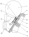
- the drawing shows a wedge color box with insert.
- a duct roller 1 is assigned a lower part 2 of a known wedge ink fountain, 2 ink metering elements 3 being arranged on the bottom part for setting a gap relative to the duct roller 1.
- a paint box insert 4 is placed on the lower part 2 and a flat gasket 5 is arranged between the lower part 2 and the underside 7 of the paint box insert.
- the underside 7 of the ink fountain insert 4 is detachably connected to the lower part 2 via at least one fastening screw 6.
- a color distribution element 8 is firmly connected to the underside 7 of the ink fountain insert 4.
- the ink distribution element 8 has an end face 9 that is operatively connected to the duct roller 1.
- the end face 9 does not touch the duct roller 1, that is, there is a small gap and, according to a second variant (not shown), the end face 9 of the ink distributor element 8 touches , for example via a rotating element, the duct roller.
- the front side 9 and the ink metering elements 3 enclose an ink supply space 10 in connection with the underside 7 of the ink fountain insert 4.
- a connector 11 for the ink supply to the ink supply space 10 is arranged on the ink distribution element 8. This connection 11 can be connected to a paint cartridge or to a paint supply system via a metering and pressure switch unit.
- Handles 12 are arranged on the ink fountain insert 4.
- connection 11 of the ink distribution element 8 is separated from the ink supply system or from the ink cartridge, if it is not part of the ink fountain insert, the fastening screw is loosened and the ink fountain insert 4 is removed from the wedge ink fountain.
- the removed unit can now be cleaned outside the printing press, and the ink supply space is also easily accessible.
Landscapes
- Inking, Control Or Cleaning Of Printing Machines (AREA)
Abstract
Description
Nachteilig ist, daß im Druckbetrieb Farbe unter den Boden des Einsatzes gelangen und diesen unterwandern kann. Das Ziel des verringerten Reinigungsaufwandes wird so in Frage gestellt. Der Einsatz läuft außerdem Gefahr, durch hydrodynamische Kräfte ausgehoben zu werden.
Ein weiteres Manko dieser Farbkasteneinsätze ist das notwendige Spiel zum Duktor, welches ein unerwünschtes Lecken der Farbe bedingt.
Nachteilig an dieser Lösung ist der große Befestigungsaufwand, der zur Gewährleistung der Dichtheit bei höheren Drücken betrieben werden muß und so auch eine optionale Nutzung erschwert. Bei einem Farbwechsel bietet die schlecht zugängliche Vorrichtung keine Zeitvorteile beim Reinigungsvorgang. Ein besonderes Problem ist dabei die sich in den Zuleitungen befindliche Restfarbe.
Einer Duktorwalze 1 ist ein Unterteil 2 eines bekannten Keilfarbkastens zugeordnet, wobei am Unterteil 2 Farbdosierelemente 3 zur Einstellung eines Spaltes gegenüber der Duktorwalze 1 angeordnet sind. Auf das Unterteil 2 ist ein Farbkasteneinsatz 4 aufgesetzt und zwischen dem Unterteil 2 und der Unterseite 7 des Farbkasteneinsatzes ist zur Abdichtung eine Flachdichtung 5 angeordnet. Die Unterseite 7 des Farbkasteneinsatzes 4 ist über mindestens eine Befestigungsschraube 6 lösbar mit dem Unterteil 2 verbunden.
Mit der Unterseite 7 des Farbkasteneinsatzes 4 ist ein Farbverteilelement 8 fest verbunden. Das Farbverteilelement 8 weist eine in Wirkverbindung mit der Duktorwalze 1 stehende Stirnseite 9 auf Nach einer ersten Variante berührt die Stirnseite 9 nicht die Duktorwalze 1, d.h. es besteht ein geringer Spalt und nach einer zweiten Variante (nicht dargestellt) berührt die Stirnseite 9 des Farbverteilelementes 8, beispielsweise über ein rotierendes Element, die Duktorwalze.
Die Stirnseite 9 und die Farbdosierelemente 3 schließen in Verbindung mit der Unterseite 7 des Farbkasteneinsatzes 4 einen Farbvorratsraum 10 ein. An dem Farbverteilelement 8 ist ein Anschluß 11 für die Farbzufuhr zu dem Farbvorratsraum 10 angeordnet. Dieser Anschluß 11 ist mit einer Farbkartusche oder über eine Dosier- und Druckschaltereinheit mit einer Farbversorgungsanlage verbindbar. Am Farbkasteneinsatz 4 sind Griffe 12 angeordnet. Bei einem Farbwechsel wird der Anschluß 11 des Farbverteilelementes 8 von der Farbversorgungsanlage bzw. von der Farbkartusche, wenn sie nicht Bestandteil des Farbkasteneinsatzes ist, getrennt, die Befestigungsschraube gelöst und der Farbkasteneinsatz 4 aus dem Keilfarbkasten herausgenommen. Nunmehr ist die herausgenommene Einheit außerhalb der Druckmaschine reinigbar, wobei auch der Farbvorratsraum leicht zugänglich ist.
- 1
- Duktorwalze
- 2
- Unterteil
- 3
- Farbdosierelement
- 4
- Farbkasteneinsatz
- 5
- Flachdichtung
- 6
- Befestigungsschraube
- 7
- Unterseite
- 8
- Farbverteilelement
- 9
- Stirnseite
- 10
- Farbvorratsraum
- 11
- Anschluß
- 12
- Griff
Claims (5)
- Keilfarbkasten für Druckmaschinen mit einem Unterteil (2) einschließlich Farbdosierelementen (3) zur Einstellung eines Spaltes gegenüber einer Duktorwalze (1), mit einem mit dem Unterteil (2) lösbar verbundenen und entfernbaren Farbkasteneinsatz (4) und einem mit dem Farbkasteneinsatz (4) verbundenen, mit einem Anschluß (11) für Druckfarbe versehenen Farbverteilelement (8), das mit seiner im geringen Abstand der Duktorwalze (1) zugeordneten Stirnseite (9) und den Farbdosierelementen (3) in Verbindung mit einer Unterseite (7) des Farbkasteneinsatzes (4) einen unter Druck stehenden Farbvorratsraum (10) bildet.
- Keilfarbkasten für Druckmaschinen nach Anspruch 1, dadurch gekennzeichnet, daß der Anschluß (11) für Druckfarbe mit einer Farbkartusche verbindbar ist.
- Keilfarbkasten für Druckmaschinen nach Anspruch 1, dadurch gekennzeichnet, daß der Anschluß (11) für Druckfarbe über einen Druckschalter mit einer Farbversorgungsanlage verbunden ist.
- Keilfarbkasten für Druckmaschinen nach Anspruch 1, dadurch gekennzeichnet, daß zwischen dem Farbkasteneinsatz (4) und dem Unterteil (2) des Keilfarbkastens eine Flachdichtung (5) angeordnet ist.
- Keilfarbkasten für Druckmaschinen nach Anspruch 1, dadurch gekennzeichnet, daß die Stirnseite (9) des Farbverteilelementes (8) als ein die Duktorwalze (1) berührendes Teil ausgebildet ist.
Applications Claiming Priority (2)
| Application Number | Priority Date | Filing Date | Title |
|---|---|---|---|
| DE19826817 | 1998-06-16 | ||
| DE19826817A DE19826817A1 (de) | 1998-06-16 | 1998-06-16 | Keilfarbkasten |
Publications (3)
| Publication Number | Publication Date |
|---|---|
| EP0965449A2 true EP0965449A2 (de) | 1999-12-22 |
| EP0965449A3 EP0965449A3 (de) | 2000-04-05 |
| EP0965449B1 EP0965449B1 (de) | 2002-08-14 |
Family
ID=7871059
Family Applications (1)
| Application Number | Title | Priority Date | Filing Date |
|---|---|---|---|
| EP99111469A Expired - Lifetime EP0965449B1 (de) | 1998-06-16 | 1999-06-12 | Keilfarbkasten |
Country Status (2)
| Country | Link |
|---|---|
| EP (1) | EP0965449B1 (de) |
| DE (2) | DE19826817A1 (de) |
Families Citing this family (1)
| Publication number | Priority date | Publication date | Assignee | Title |
|---|---|---|---|---|
| DE20204841U1 (de) | 2002-03-26 | 2002-09-05 | Gramsch, Mathias, 26209 Hatten | Farbkasten für eine Druckmaschine und Druckmaschine |
Family Cites Families (6)
| Publication number | Priority date | Publication date | Assignee | Title |
|---|---|---|---|---|
| US3199451A (en) * | 1963-08-02 | 1965-08-10 | Koppers Co Inc | Ink distribution device |
| GB1585452A (en) * | 1977-04-18 | 1981-03-04 | Harris Corp | Inking mechanism |
| DE2929891A1 (de) * | 1979-07-24 | 1981-02-12 | Roland Man Druckmasch | Farbkasten fuer eine rotationsdruckmaschine |
| SE420064B (sv) * | 1980-03-11 | 1981-09-14 | Wifag Maschf | Insatsferglada |
| DE4339939C2 (de) * | 1993-11-24 | 1995-10-12 | Robert Wagner | Vorrichtung zur Zufuhr von Druckfarbe in ein Farbwerk einer Offsetdruckmaschine |
| DE19640775A1 (de) * | 1996-10-02 | 1998-04-09 | Roland Man Druckmasch | Einsatz für einen Keilfarbkasten von Druckmaschinen |
-
1998
- 1998-06-16 DE DE19826817A patent/DE19826817A1/de not_active Withdrawn
-
1999
- 1999-06-12 DE DE59902319T patent/DE59902319D1/de not_active Expired - Fee Related
- 1999-06-12 EP EP99111469A patent/EP0965449B1/de not_active Expired - Lifetime
Also Published As
| Publication number | Publication date |
|---|---|
| EP0965449A3 (de) | 2000-04-05 |
| DE19826817A1 (de) | 1999-12-23 |
| DE59902319D1 (de) | 2002-09-19 |
| EP0965449B1 (de) | 2002-08-14 |
Similar Documents
| Publication | Publication Date | Title |
|---|---|---|
| DE3146223C2 (de) | Feucht-Farbwerk für Offsetdruckmaschinen | |
| EP0141168B1 (de) | Farbwerksvoreinstellung | |
| DE2300289C2 (de) | Vorrichtung zum Auftragen flüssiger oder pastöser Farbe für Siebdruckmaschinen | |
| EP0280957B1 (de) | Farbwerk für eine Rotations-Offsetdruckmaschine | |
| DE4013465A1 (de) | Druckmaschine mit wascheinrichtung | |
| DE4424581C1 (de) | Vorrichtung zum Entfernen von Farbe aus einem Farbwerk | |
| EP0965449B1 (de) | Keilfarbkasten | |
| DE4339939C2 (de) | Vorrichtung zur Zufuhr von Druckfarbe in ein Farbwerk einer Offsetdruckmaschine | |
| EP1127688B1 (de) | Verfahren und Einrichtung zum Zuführen von Druckfarbe in Farbkästen von Druckmaschinen | |
| EP0924073B1 (de) | Einrichtung zum Dosieren einer Beschichtungsflüssigkeit für Bedruckstoffe in einer Druckmaschine | |
| DE3105975C2 (de) | ||
| DE2725725A1 (de) | Flachoffsetpresse | |
| DE10009661B4 (de) | Verfahren und Einrichtung zum Zuführen von Druckfarbe in Farbkästen von Druckmaschinen | |
| DE4326593C2 (de) | Druckfarbenzuführungseinrichtung | |
| DE69723742T3 (de) | Farbrakel | |
| DE19826810A1 (de) | Verfahren und Einrichtung zur Farbzufuhr | |
| EP0965447A2 (de) | Farbkasten mit automatischer Farbversorgung | |
| DE19957464A1 (de) | Einrichtung zur Abdichtung einer Farbversorgung an Druckmaschinen | |
| EP1957276B1 (de) | Vorrichtung und verfahren zum bedrucken von zylindrischen flaschenver schlüssen | |
| DE10116512A1 (de) | Automatische Vorrichtung zur Veränderung des Farbniveaus in einer Durckmaschine | |
| EP1060886B1 (de) | Verfahren und Einrichtung zum Zuführen von Druckfarbe in Farbkästen von Druckmaschinen | |
| EP1674261A2 (de) | Reinigungssystem für eine Druckmaschine | |
| DE1232166B (de) | Farbwerk zum Spuelen und Einfaerben von Duktorwalzen von Buchdruck-, Offset- und aehnlichen Maschinen | |
| DE2316635C3 (de) | Reinigungsvorrichtung für das aus einer Farbkastenwalze, einer Heberwalze und einer Zwischenwalze bestehende Farbwerk einer Klein-Offsetdruckmaschine | |
| DE2406940C3 (de) | Einwegfarbkasten einer Klein-Offset-Rotationsdruckmaschine |
Legal Events
| Date | Code | Title | Description |
|---|---|---|---|
| PUAI | Public reference made under article 153(3) epc to a published international application that has entered the european phase |
Free format text: ORIGINAL CODE: 0009012 |
|
| AK | Designated contracting states |
Kind code of ref document: A2 Designated state(s): DE FR GB IT |
|
| AX | Request for extension of the european patent |
Free format text: AL;LT;LV;MK;RO;SI |
|
| PUAL | Search report despatched |
Free format text: ORIGINAL CODE: 0009013 |
|
| AK | Designated contracting states |
Kind code of ref document: A3 Designated state(s): AT BE CH CY DE DK ES FI FR GB GR IE IT LI LU MC NL PT SE |
|
| AX | Request for extension of the european patent |
Free format text: AL;LT;LV;MK;RO;SI |
|
| 17P | Request for examination filed |
Effective date: 20000306 |
|
| AKX | Designation fees paid |
Free format text: DE FR GB IT |
|
| 17Q | First examination report despatched |
Effective date: 20001127 |
|
| GRAG | Despatch of communication of intention to grant |
Free format text: ORIGINAL CODE: EPIDOS AGRA |
|
| GRAG | Despatch of communication of intention to grant |
Free format text: ORIGINAL CODE: EPIDOS AGRA |
|
| GRAH | Despatch of communication of intention to grant a patent |
Free format text: ORIGINAL CODE: EPIDOS IGRA |
|
| GRAH | Despatch of communication of intention to grant a patent |
Free format text: ORIGINAL CODE: EPIDOS IGRA |
|
| GRAA | (expected) grant |
Free format text: ORIGINAL CODE: 0009210 |
|
| AK | Designated contracting states |
Kind code of ref document: B1 Designated state(s): DE FR GB IT |
|
| REG | Reference to a national code |
Ref country code: GB Ref legal event code: FG4D Free format text: NOT ENGLISH |
|
| REF | Corresponds to: |
Ref document number: 59902319 Country of ref document: DE Date of ref document: 20020919 |
|
| GBT | Gb: translation of ep patent filed (gb section 77(6)(a)/1977) |
Effective date: 20021129 |
|
| ET | Fr: translation filed | ||
| PLBE | No opposition filed within time limit |
Free format text: ORIGINAL CODE: 0009261 |
|
| STAA | Information on the status of an ep patent application or granted ep patent |
Free format text: STATUS: NO OPPOSITION FILED WITHIN TIME LIMIT |
|
| 26N | No opposition filed |
Effective date: 20030515 |
|
| PGFP | Annual fee paid to national office [announced via postgrant information from national office to epo] |
Ref country code: IT Payment date: 20090624 Year of fee payment: 11 Ref country code: FR Payment date: 20090615 Year of fee payment: 11 |
|
| PGFP | Annual fee paid to national office [announced via postgrant information from national office to epo] |
Ref country code: GB Payment date: 20090618 Year of fee payment: 11 Ref country code: DE Payment date: 20090626 Year of fee payment: 11 |
|
| GBPC | Gb: european patent ceased through non-payment of renewal fee |
Effective date: 20100612 |
|
| REG | Reference to a national code |
Ref country code: FR Ref legal event code: ST Effective date: 20110228 |
|
| PG25 | Lapsed in a contracting state [announced via postgrant information from national office to epo] |
Ref country code: IT Free format text: LAPSE BECAUSE OF NON-PAYMENT OF DUE FEES Effective date: 20100612 |
|
| PG25 | Lapsed in a contracting state [announced via postgrant information from national office to epo] |
Ref country code: DE Free format text: LAPSE BECAUSE OF NON-PAYMENT OF DUE FEES Effective date: 20110101 |
|
| PG25 | Lapsed in a contracting state [announced via postgrant information from national office to epo] |
Ref country code: FR Free format text: LAPSE BECAUSE OF NON-PAYMENT OF DUE FEES Effective date: 20100630 |
|
| PG25 | Lapsed in a contracting state [announced via postgrant information from national office to epo] |
Ref country code: GB Free format text: LAPSE BECAUSE OF NON-PAYMENT OF DUE FEES Effective date: 20100612 |